Burkert PTB 03 ATEX 1030 X User manual

Operating Instructions
Bedienungsanleitung
Manuel d‘utilisation
PTB 03 ATEX 1030 X
Device with II 2G/D Ex approval
Geräte mit II 2G/D Ex Zulassung
Appareils avec mode de protection II 2G/D Ex
Example/Beispiel/Exemple
Coil type 0780 with valve body type 0330
Spule Typ 0780 mit Gehäuse Typ 0330
Bobine type 0780 avec le corps type 0330

We reserve the right to make technical changes without notice.
Technische Änderungen vorbehalten.
Sous resérve de modification techniques.
© 2008 - 2013 Bürkert Werke GmbH
Operating Instructions 1309/12_EU-ML_00804717 / Original DE

3
1. THE OPERATING INSTRUCTIONS .........................................................4
1.1. Symbols ..............................................................................................4
2. INTENDED USE ................................................................................................5
2.1. Restrictions ........................................................................................5
2.2. Ex-Approval .......................................................................................5
2.3. Special instructions in explosion-risk areas ............................... 6
3. GENERAL SAFETY INSTRUCTIONS .....................................................6
4. GENERAL INFORMATION ...........................................................................7
4.1. Contact Address ..............................................................................7
4.2. Warranty .............................................................................................7
4.3. Information on the Internet .............................................................7
5. APPLICATION CONDITIONS .....................................................................8
5.1. Special conditions ...........................................................................8
6. TECHNICAL DATA / SAFE OPERATION ..............................................9
6.1. Conformity ......................................................................................... 9
6.2. Standards ...........................................................................................9
6.3. Operating Conditions ......................................................................9
6.4. General Technical Data ................................................................11
7. ASSEMBLY AND DISASSEMBLY .........................................................12
7.1. Safety Instructions .........................................................................12
7.2. Installation of valve .........................................................................13
7.3. Electrical connection .....................................................................13
7.4. Disassembly ....................................................................................14
8. START-UP .........................................................................................................14
8.1. Safety Instructions .........................................................................14
9. MAINTENANCE, REPAIR, TROUBLESHOOTING .........................15
9.1. Maintenance and repair ................................................................15
9.2. Troubleshooting ..............................................................................15
10. ACCESSORIES ...........................................................................................15
10.1. Spare parts ....................................................................................15
11. TRANSPORT, STORAGE, DISPOSAL ..............................................16
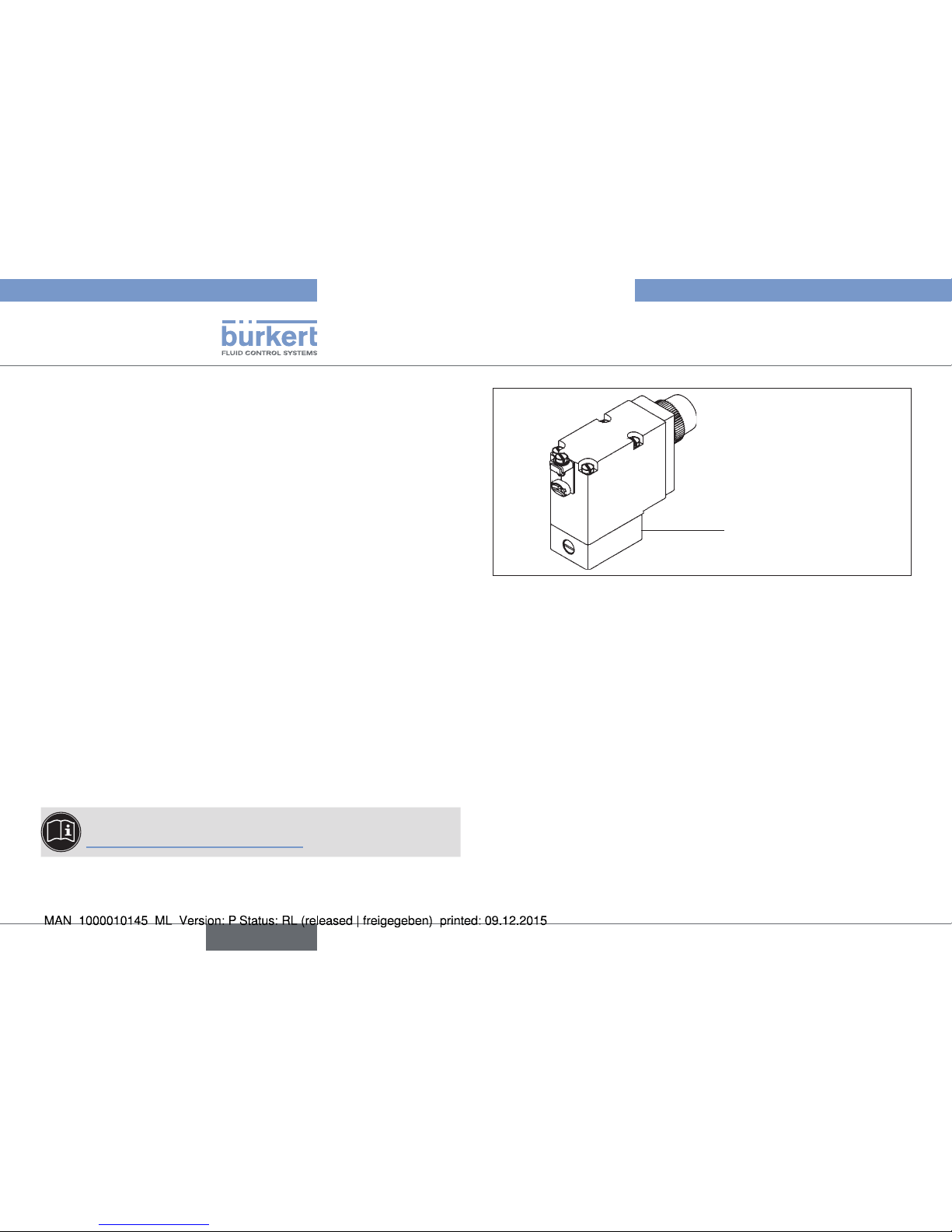
Device with II 2G/D Ex certification
english
PTB 03 ATEX 1030 X

4
The Operating Instructions
1. THE OPERATING INSTRUCTIONS
The operating instructions describe the entire life cycle of the device.
Keep these instructions in a location which is easily accessible to
every user and make these instructions available to every new owner
of the device.
The operating instructions contain important safety
information!
Failure to observe these instructions may result in hazardous situa-
tions. The operating instructions must be read and understood.
• Carefully read the operating instructions before using the device.
• In particular observe the chapter entitled “Intended Use”, and
“General Safety Instructions” as well as the chapter entitled
„Application Conditions“.
1.1. Symbols
In the instructions, the following symbols are used to identify important
information:
DANGER!
Warns of an immediate danger!
• Failure to observe the warning may result in a fatal or serious injury.
WARNING!
Warns of a potentially dangerous situation!
• Failure to observe the warning may result in serious injuries or
death.
CAUTION!
Warns of a possible danger!
• Failure to observe the warning may result in moderately serious
or minor injuries.
NOTE!
Warns of damage to property!
Important tips and recommendations.
Refers to information in these operating instructions or in
other documentation.
→designates a procedure which you must carry out.
english
PTB 03 ATEX 1030 X

5
Intended Use
2. INTENDED USE
Incorrect use may be a hazard to people, nearby equipment
and the environment.
• The device serves exclusively as a solenoid valve for the media
stated in the data sheet and for use in Explosion Group IIC,
Category 2G and Temperature Class T4 or T5 (see data on the
- Ex approval plate).
• The device may be used only in category 2D with the temperatures
T135 °C and/or 100 °C as well as for the designated application
cases specified in chapter “5. Application Conditions” and in con-
junction with third-party devices and components recommended
and authorized by Bürkert.
• The applied ignition protection types are the pressure-resistant
casing “d” with increased safety “e”. The safety fuse incorpo-
rated in version PD29 is executed in ignition protection type
encapsulation “m”. The proximity switch, which can be optionally
incorporated in all versions, is executed in ignition protection
type intrinsic safety “ia”.
The composition of the ignition protection code follows the igni-
tion protection types of the components used in each case.
• Correct transportation, correct storage and installation and careful
use and maintenance are essential for reliable and problem-free
operation.
Any other use is considered improper use. Bürkert is not liable
for any resulting damage. The user alone bears the risk.
• Use the device only as intended.
2.1. Restrictions
If exporting the device, observe any existing restrictions.
2.2. Ex-Approval
The Ex approval is only valid if you use the modules and components
authorised by Bürkets in such a way as described in this operating
manual.
The coil type 0770/0780 may only be used in combination with addi-
tional components that have been approved by Bürkert. Otherwise, the
Ex approval will expire!
If you make any unauthorized changes to the device, the modules or
the components, the Ex approval will also expire.
The EC Qualification Test Certificate PTB 03 ATEX 1030 X and the
IECEx Certificate of Conformity IECEx PTB 05.0026X has been
drawn up by the:
PTB (Physikalisch Technische Bundesanstalt)
Bundesallee 100
38116 Braunschweig
who also audited the manufacture (CE0102).
The EC type approval test certificate can be found on the Internet at:
www.burkert.com
english
PTB 03 ATEX 1030 X

6
General Safety Instructions
2.3. Special instructions in explosion-risk
areas
WARNING!
Danger caused by electrostatic charge!
If there is a sudden discharge from electrostatically charged devices
or persons, there is a danger of explosion in the explosion-risk area.
• Take appropriate measures to prevent electrostatic charges in
explosion-risk areas.
• Clean the device surface by gently wiping it with a damp or
antistatic cloth only.
Additional special conditions can be found under “5.1” of
these operating instructions.
3. GENERAL SAFETY INSTRUCTIONS
These safety instructions do not take into account
• any contingencies or events which may occur during the installation,
operation and maintenance of the devices.
• local safety regulations, the observance of which is the responsibility
of the operator, also with respect to the installation personnel.
Danger of explosion!
• The device is a sealed system. It must not be opened
Danger of electrostatic charge!
Acute risk of injury from hazardous structure-borne voltage!
Risk of damage to the device due to short circuit!
• Before starting work, switch off the power supply and secure to
prevent it being switched on again!
• Observe the applicable accident prevention and safety regula-
tions for electrical devices!
Danger - high pressure!
• There is a serious risk of injury when reaching into the
equipment.
• Before loosening the lines and valves, turn off the pressure and
vent the lines.
• Observe the currently valid accident prevention and safety
regulations!
english
PTB 03 ATEX 1030 X

7
General Information
Danger of explosion caused by electrostatic charge!
If there is a sudden discharge from electrostatically charged
devices or persons, there is a danger of explosion in the Ex area.
• Take appropriate measures to prevent electrostatic charges in
the Ex area.
• Clean the device surface by gently wiping it with a damp or
antistatic cloth.
General hazardous situations.
To prevent injury, ensure that:
• That the system cannot be activated unintentionally.
• That no unauthorized changes are performed on the system.
• Only expert and instructed personnel with appropriate tools
carry out any work on the system.
• The device may be operated only when in perfect condition and
in consideration of the operating instructions.
• The general rules of technology apply to application planning
and operation.
4. GENERAL INFORMATION
4.1. Contact Address
Germany
Bürkert Fluid Control Systems
Sales Center
Chr.-Bürkert-Str. 13-17
D-74653 Ingelfingen
Tel. + 49 (0) 7940 - 10 91 111
Fax + 49 (0) 7940 - 10 91 448
E-mail: [email protected]
International
Contact addresses can be found on the final pages of the printed
operating instructions.
And also on the Internet under: www.burkert.com
4.2. Warranty
The warranty is only valid if the device is used as intended in accordance
with the specified application conditions.
4.3. Information on the Internet
The operating manual and the data sheets can be found on the Internet
under: www.burkert.com
english
PTB 03 ATEX 1030 X

8
Application Conditions
5. APPLICATION CONDITIONS
5.1. Special conditions
5.1.1. Short-circuit protection
Each electromagnet shall be provided on the line with a short-circuit
protection in the form of a fuse designed to meet the magnet starting
current (max. 3 x Irating in accordance with IEC 60127-2-1) or a
motor overload trip instantaneous short-circuit and thermal release
(Adjustment to match the pull-in current).
• At very low pull-in currents of the solenoid the fuse with the lowest
current value is adequate according to the stated IEC standard.
This fuse may be mounted in the associated supply unit or must
be connected in series separately.
• The rated voltage of the fuse must be equal to or larger than the
quoted nominal voltage of the magnet.
• The switch-off capability of the fuse cartridge must be equal to or
greater than the maximum theoretical short-circuit current at the
installation location (normally 1500 A).
• In the case of versions PD30 of the solenoid, short-circuit pro-
tection must be assured by the operator.
• In the case of version PD29 of the solenoid, the fuse is installed in
the terminal box of the device.
More detailed descriptions are to be found in the section
“6. Technical data / Safe operation”.
Fuse ... A
5.1.2. Operation with associated valve body
The solenoid coils Type 77. / 78. may only be operated with a valve
body satisfying the following requirements.
For the valve body, the following materials may be used:
• metal (brass, aluminium, stainless steel) or
• plastics (e,g, polyamide PA 6 GV ...)
5.1.3. Manual operation / approximity switch
The solenoid armature can be manually operated via the push
button. The push button may be locked by depressing and turning
by 90°.
As an alternative to manual operation, the solenoid can be equipped
with a proximity switch. The internal code for this version is CF 15.
english
PTB 03 ATEX 1030 X

9
Technical data / Safe operation
5.1.4. Model with a terminal box
DANGER!
Risk of explosion!
• Only permanently laid cables and wiring may be inserted.
• The operator must provide suitable stress relief.
• Wires with an outside diameter of 6 to 13 mm may be used.
Observe the maximum thermal loading of the cables or wires to
be inserted.
• The inserted break-off seal must be matched to the diameter of
the cable or wire.
• The rated cross-section of the cable or wire strands must be at
least 0.75 mm² and may not exceed 2.5 mm².
• The screws for fixing the cover of the terminal box must be tight-
ened with a torque of 1 Nm (± 5 %).
The solenoid coils may also be executed with a terminal box, with
or without fuse/contactor (to separate Design Type Inspection Cer-
tificate) as desired.
For protection against inadvertent opening of the cover, the latter
bears the marking:
Open only when the voltage is switched off!
6. TECHNICAL DATA / SAFE
OPERATION
6.1. Conformity
The coil type 0770/0780 is compliant with the EC Directives according
to the EC Declaration of Conformity.
6.2. Standards
Refer to the EC type approval test certificate and/or the EC Declaration
of conformity for the applicable standards verifying conformity with the
EC directives.
6.3. Operating Conditions
DANGER!
Risk of explosion by excedance technical data!
Exceeding the technical data indicated on the type label increases
the explosion risk!
• Never exceed the technical data indicated on the type label!
6.3.1. Maximum permissible ambient
temperature range
Please observe the maximum permissible ambient temperature range
given under Operating conditions of the coils for each type!
Version Maximum permissible ambient temperature
range
07xx -30 °C ... +55 °C
english
PTB 03 ATEX 1030 X

10
Technical data / Safe operation
6.3.2. Type of protection
IP65 to EN 60529 (DIN VDE 0470 Part 1)
6.3.3. Location and description of the type
label
Type label coil
Type label IEC Ex
Warning notices
Fuse
...A
IEC EX Approval number
Protection class - Temperature class
Fig. 1: Location of the type label
PTB approval number
Protection class, Temperature class
Type and design
Id. number of the coil, Date of manufacture
Serial number of the coil, Inspection body
Voltage (± 10 %), Current type, Power consumption
Fig. 2: Description of the type label
6.3.4. Dimensions
Connection type Length
(mm)
Width
(mm)
Height
(mm)
Molded-in cable 96 32 56
Terminal box with/
without safety fuse
123 60 113
english
PTB 03 ATEX 1030 X

11
Technical data / Safe operation
6.3.5. Type of explosion protection
The composition of the explosion protection code follows the explosion
protection types of the components used in each case:
Solenoid with or without
terminal box
II 2 G Ex d e IIC T4 resp. T5
II 2 D Ex tD A21 IP 65 T135 °C resp.
T100 °C
Solenoid with terminal
box and fuse
II 2 G Ex d e mb IIC T4
II 2 D Ex tD A21 IP65 T135 °C
Solenoid without terminal
box with proximity switch
II 2 G Ex d e ia IIC T4 resp. T5
II 2 D Ex tD A21 IP65 T135 °C resp.
T100 °C
Solenoid with terminal
box, fuse and proximity
switch
II 2 G Ex d e ia mb IIC T4
II 2 D Ex tD A21 IP65 T135 °C
6.4. General Technical Data
6.4.1. Electrical Data
Type 77. - ... - ... - . 78. - ... - ... - .
Temperature class T4 T5
Type of current Universal Universal
Rated voltage 24 ... 240 V 24 ... 240 V
Voltage tolerance +10 % / -10 % +10 % / -10 %
Rated current 0,085 ... 0,014 A 0,085 ... 0,014 A
Pick-up current 01,66 ... 0,166 A 01,66 ... 0,166 A
Pick-up power 40 W 40 W
Power consumption for
holding in equilibrium
3 W 3W
Max. number of
switching actuations ca
20 / min 10 / min
6.4.2. Electrical connection
Version
code
Execution Internal
Code
PD30* * Permanently installed rubber sheathed
cable of Type H05 RN-F3G0.75
****JWxx
english
PTB 03 ATEX 1030 X

12
Assembly and disassembly
Version
code
Execution Internal
Code
PD30
** Terminal box with cable bushing M20
x 1.5, without fuse
JA02
Terminal box with threaded nipple M20 x
1.5, without fuse
JA08
Terminal box with threaded nipple NPT
1/2, without fuse
JA09
Terminal box with threaded nipple G 1/2,
without fuse
JA10
PD29 ***
** Terminal box with cable bushing M20 x
1.5 and fuse
JA01
Terminal box with threaded nipple M20 x
1.5 and fuse
JA05
Terminal box with threaded nipple NPT
1/2 and fuse
JA06
Terminal box with threaded nipple G 1/2
and fuse
JA07
* The connecting cable of solenoid Type 07xx must be laid permanently
such that it is adequately protected from mechanical damage
** Cable bushing to separate Design Inspection Certificate
*** Fuse protection PD29 to separate type approval test certificate
**** Different cable lengths
7. ASSEMBLY AND DISASSEMBLY
7.1. Safety Instructions
DANGER!
Danger of explosion!
The device is a sealed system. The unit must not be dismantled!
The following safety regulations must be observed:
• The surface of the device may develop an electrostatic charge.
In areas with an explosion hazard, the surface of the units may
only be cleaned with a damp cloth.
• Only permanently laid cables and wiring may be inserted.
• The operator must provide suitable stress relief.
• Wires with an outside diameter of 6 to 13 mm may be used.
Observe the maximum thermal loading of the cables or wires to
be inserted.
• The inserted break-off seal must be matched to the diameter of
the cable or wire.
• The rated cross-section of the cable or wire strands must be at
least 0.75 mm² and may not exceed 2.5 mm².
• The screws for fixing the cover of the terminal box must be tight-
ened with a torque of 1 Nm (±5%).
• The connection nut (clamping nut) of the cable gland on the ter-
minal box must be tightened with a torque of 1.5 Nm (± 5 %).
english
PTB 03 ATEX 1030 X

13
Assembly and disassembly
DANGER!
Danger of high voltage!
Acute risk of injury from hazardous structure-borne voltage!
Risk of damage to the device due to short circuit!
• Before starting work, switch off the power supply and secure to
prevent it being switched on again!
• Live terminals in the terminal box can cause electric shock, short
circuit or explosion. Switch off the power supply before open-
ing the terminal box.
• The connecting cables to the electromagnets must be secure,
and be laid so that they are adequately protected from mechani-
cal damage.
• Observe the applicable accident prevention and safety regula-
tions for electrical devices!
WARNING!
Danger - high pressure!
Interventions in the pneumatic system represent an acute risk of
injury.
• First switch off pressure before disconnecting lines and valves.
• Observe the flow direction during installation.
• Observe the applicable accident prevention and safety regula-
tions for pneumatic systems.
7.2. Installation of valve
The solenoid valve can be mounted in any position.
Preferably with solenoid system mounted at the top.
Procedure:
→Clean pipelines.
→Connect a dirt trap upstream.
→Seal pipeline connections with PTFE tape.
→Screws in pipelines.
Make certain the direction of flow is correct!
→Check valve for leakage.
7.3. Electrical connection
DANGER!
Risk of injury due to electrical shock!
• Before reaching into the system, switch off the electrical power
supply and secure to prevent reactivation!
• Observe applicable accident prevention and safety regulations
for electrical equipment!
If the protective conductor contact between coil and body is
missing, there is danger of electrical shock!
• Always connect protective conductor.
• Check electrical continuity between coil and body.
english
PTB 03 ATEX 1030 X

14
Start-up
The connection cable is encapsulated with the coil and
cannot be removed.
→Attach the electrical connection.
7.4. Disassembly
DANGER!
Risk of electric shock!
There is a serious risk of injury when reaching into the equipment.
• Only trained electrical engineers may work on the electrical
system.
• Before starting work, always switch off the power supply and
safeguard to prevent re-activation!
• Observe applicable accident prevention and safety regulations
for electrical equipment!
Procedure:
→Disconnect the power connection.
→Disconnect the valve body from the pipeline.
NOTE!
Malfunctions as a result of contamination!
• In case of new installation, remove old PTFE tape from the connec-
tions. Residues or parts of the tape must not get into the pipeline.
8. START-UP
8.1. Safety Instructions
WARNING!
Danger due to improper operation!
Improper operation may result in injuries as well as damage to the
device and the area around it.
• Before start-up, ensure that the operating personnel are familiar
with and completely understand the contents of the operating
instructions.
• In particular observe the safety instructions and intended use.
• The device may be started by adequately trained personnel only.
Before commissioning, ensure that:
• The device has been correctly installed,
• The connections have been correctly made,
• The device is not damaged,
• All bolts are securely tightened.
english
PTB 03 ATEX 1030 X

15
Maintenance, Repair, Troubleshooting
9. MAINTENANCE, REPAIR,
TROUBLESHOOTING
9.1. Maintenance and repair
DANGER!
Danger due to improper maintenance, repair and inspection
work!
• The maintenance and inspection work on the device may be carried
out by authorized technicians only and with the appropriate tools!
• Repairs on the device may only be carried out by the
manufacturer!
• When performing repair or maintenance work on the system, the
valve may not be opened and the protective-conductor connection
may not be disconnected!
9.2. Troubleshooting
In the event of faults, make sure that:
• the device has been installed according to the specifications,
• the connection has been established properly,
• the device is not damaged,
• all screws have been tightened,
• the voltage and pressure have been switched on,
• the pipelines are free.
10. ACCESSORIES
CAUTION!
Risk of injury and / or damage by the use of incorrect parts!
Incorrect accessories and unsuitable parts may cause injuries and
damage the device and the surrounding area.
• Use only original accessories and original spare supplied by
Bürkert.
10.1. Spare parts
For electromagnet models with terminal boxes, fuses of the Type 1058
with approval PTB 01 ATEX 2064 U can be used in Temperature
Class T4.
Fuse
Type 1058
Order
No.
0.063 A 153717
0.080 A 153745
0.100 A 153718
0.125 A 153719
0.160 A 153720
0.200 A 153731
0.315 A 153733
0.400 A 153734
0.500 A 153735
0.630 A 153736
0.800 A 153737
english
PTB 03 ATEX 1030 X

16
Transport, Storage, Disposal
Fuse
Type 1058
Order
No.
1.000 A 153738
1.250 A 153739
1.600 A 153746
2.000 A 153740
3.150 A 153742
11. TRANSPORT, STORAGE, DISPOSAL
NOTE!
Transport damages!
Inadequately protected equipment may be damaged during
transport.
• During transportation protect the device against wet and dirt in
shock-resistant packaging.
• Avoid exceeding or dropping below the allowable storage
temperature.
Incorrect storage may damage the device.
• Store the device in a dry and dust-free location!
• Storage temperature: -40 … +60 °C.
Damage to the environment caused by device components
contaminated with media.
• Ensure the device and packaging are disposed of in an environ-
mentally sound manner.
• Observe applicable regulations relating to refuse disposal and
the environment.
english
PTB 03 ATEX 1030X

17
1. BEDIENUNGSANLEITUNG ......................................................................18
1.1. Darstellungsmittel ...........................................................................18
2. BESTIMMUNGSGEMÄSSE VERWENDUNG ...................................19
2.1. Beschränkungen ............................................................................19
2.2. Ex-Zulassung ...................................................................................19
2.3. Besondere Hinweise im Ex-Bereich ..........................................20
3. ALLGEMEINE SICHERHEITSHINWEISE...........................................20
4. ALLGEMEINE HINWEISE .......................................................................... 21
4.1. Kontaktadressen .............................................................................21
4.2. Gewährleistung...............................................................................21
4.3. Informationen im Internet ..............................................................21
5. EINSATZBEDINGUNGEN ......................................................................... 22
5.1. Besondere Bedingungen .............................................................22
6. TECHNISCHE DATEN / SICHERER BETRIEB...............................23
6.1. Konformität .......................................................................................23
6.2. Normen .............................................................................................23
6.3. Betriebsbedingungen ....................................................................23
6.4. Allgemeine Technische Daten .....................................................25
7. MONTAGE UND DEMONTAGE ..............................................................26
7.1. Sicherheitshinweise .......................................................................26
7.2. Installation des Ventils ...................................................................27
7.3. Elektrischer Anschluss ..................................................................27
7.4. Demontage ......................................................................................28
8. INBETRIEBNAHME ......................................................................................28
9. WARTUNG, REPARATUR, FEHLERBEHEBUNG ...........................29
9.1. Wartung und Reparatur ................................................................29
9.2. Fehlerbehebung ..............................................................................29
10. ERSATZTEILE ...............................................................................................29
10.1. Zubehör ..........................................................................................29
11. TRANSPORT, LAGERUNG, ENTSORGUNG ................................. 30
Geräte mit II 2G/D Ex Zulassung
PTB 03 ATEX 1030 X
deutsch

18
Bedienungsanleitung
1. BEDIENUNGSANLEITUNG
Die Bedienungsanleitung beschreibt den gesamten Lebenszyklus
des Geräts. Bewahren Sie diese Anleitung so auf, dass sie für jeden
Benutzer gut zugänglich ist und jedem neuen Eigentümer des Geräts
wieder zur Verfügung steht.
Die Bedienungsanleitung enthält wichtige Informationen zur
Sicherheit!
Das Nichtbeachten dieser Hinweise kann zu gefährlichen Situationen
führen. Die Anleitung muss gelesen und verstanden werden.
• Lesen Sie die Bedienungsanleitung vor dem Einsatz des Geräts
sorgfältig durch.
• Beachten Sie vor allem die Kapitel „Bestimmungsgemäße
Verwendung“, und „Allgemeine Sicherheitshinweise“ sowie das
Kapitel „Einsatzbedingungen“.
1.1. Darstellungsmittel
Für die Kennzeichnung wichtiger Informationen werden in der Anleitung
folgende Darstellungsmittel verwendet:
GEFAHR!
Warnt vor einer unmittelbaren Gefahr!
• Bei Nichtbeachtung sind Tod oder schwere Verletzungen die Folge.
WARNUNG!
Warnt vor einer möglicherweise gefährlichen Situation!
• Bei Nichtbeachtung drohen schwere Verletzungen oder Tod.
VORSICHT!
Warnt vor einer möglichen Gefährdung!
• Nichtbeachtung kann mittelschwere oder leichte Verletzungen
zur Folge haben.
HINWEIS!
Warnt vor Sachschäden!
• Bei Nichtbeachtung kann Gerät oder Anlage beschädigt werden.
Bezeichnet wichtige Zusatzinformationen, Tipps und
Empfehlungen.
Verweist auf Informationen in dieser Bedienungsanleitung
oder in anderen Dokumentationen.
→markiert einen Arbeitsschritt, den Sie ausführen müssen.
PTB 03 ATEX 1030 X
deutsch

19
Bestimmungsgemäße Verwendung
2. BESTIMMUNGSGEMÄSSE
VERWENDUNG
Bei nicht bestimmungsgemäßem Einsatz können Gefahren für
Personen, Anlagen in der Umgebung und die Umwelt entstehen.
• Das Gerät dient ausschließlich als Magnetventil für die Iaut Daten-
blatt zulässigen Medien und für den Einsatz in Explosionsgruppe
IIC, Kategorie 2G und Temperaturklasse T4 oder T5 (siehe Anga-
ben auf dem - Zulassungsschild).
• Das Gerät darf nur für den Einsatz in Kategorie 2D mit den Tem-
peraturen T135 °C bzw. 100 °C sowie für die im Kapitel „5. Ein-
satzbedingungen“ vorgesehenen Einsatzfällen und in Verbindung
mit von Bürkert empfohlenen bzw. zugelassenen Fremdgeräten
und -komponenten verwendet werden.
• Die angewendeten Zündschutzarten sind die Druckfeste Kap-
selung „d“ mit Erhöhter Sicherheit „e“. Die Sicherung, die bei
Ausführung PD29 eingebaut ist, ist in Zündschutzart Vergusskap-
selung „m“ ausgeführt. Der Näherungsschalter, der optional bei
allen Ausführungen eingebaut werden kann, ist in Zündschutzart
Eigensicherheit „ia“ ausgeführt. Die Zusammensetzung des Zünd-
schutzartenkennzeichens richtet sich nach den Zündschutzarten
der jeweils verwendeten Komponenten.
• Voraussetzungen für den sicheren und einwandfreien Betrieb sind
sachgemäßer Transport, sachgemäße Lagerung und Installation
sowie sorgfältige Bedienung und Instanthaltung.
Eine andere oder darüber hinausgehende Benutzung gilt als nicht
bestimmungsgemäß. Für hieraus resultierende Schäden haftet
Bürkert nicht. Das Risiko trägt allein der Anwender.
• Das Gerät nur bestimmungsgemäß einsetzen.
2.1. Beschränkungen
Beachten Sie bei der Ausfuhr des Systems/Geräts gegebenenfalls
bestehende Beschränkungen.
2.2. Ex-Zulassung
Die Ex-Zulassung ist nur gültig, wenn Sie die von Bürkert zugelassenen
Module und Komponenten so verwenden, wie es in dieser Bedienungs-
anleitung beschrieben ist.
Die Magnetspule Typ 0770/0780 darf nur in Kombination mit den
von Bürkert freigegebenen Zusatzkomponenten eingesetzt werden,
andernfalls erlischt die Ex-Zulassung!
Nehmen Sie unzulässige Veränderungen am Gerät, den Modulen oder
Komponenten vor, erlischt die Ex-Zulassung ebenfalls.
Die EG-Baumusterprüfbescheinigung PTB 03 ATEX 1030 und das
IECEx Certificate of Conformity IECEx PTB 05.0026X wurde von
der:
PTB (Physikalisch Technische Bundesanstalt)
Bundesallee 100,
38116 Braunschweig
ausgestellt, die auch die Fertigung auditiert (CE 102).
Die EG-Baumusterprüfbescheinigung finden Sie im Internet unter:
www.buerkert.de
PTB 03 ATEX 1030 X
deutsch

20
Allgemeine Sicherheitshinweise
2.3. Besondere Hinweise im Ex-Bereich
WARNUNG!
Gefahr durch elektrostatische Aufladung!
Bei plötzlicher Entladung elektrostatisch aufgeladener Geräte oder
Personen besteht im Ex-Bereich Explosionsgefahr.
• Durch geeignete Maßnahmen sicherstellen, dass es im Ex-
Bereich zu keinen elektrostatischen Aufladungen kommen kann.
• Die Geräteoberfläche nur durch leichtes Abwischen mit einem
feuchten oder antistatischen Tuch reinigen.
Weitere Besondere Bedingungen finden Sie unter „5.1“ in
dieser Bedienungsanleitung.
3. ALLGEMEINE
SICHERHEITSHINWEISE
Diese Sicherheitshinweise berücksichtigen keine:
• Zufälligkeiten und Ereignisse, die bei Montage, Betrieb und Wartung
der Geräte auftreten können.
• ortsbezogenen Sicherheitsbestimmungen, für deren Einhaltung,
auch in Bezug auf Montagepersonal, der Betreiber verantwortlich ist.
Explosionsgefahr!
• Das Gerät ist Teil eines geschlossenen Systems und darf nicht
während des Betriebs demontiert werden.
Gefahr durch elektrische Spannung!
Akute Verletzungsgefahr durch gefährliche Korperspannung!
Gefahr der Beschädigung des Geräts durch Kurzschluss!
• Vor Eingriffen in das Gerät oder die Anlage, Spannung abschal-
ten und vor Wiedereinschalten sichern!
• Die geltenden Unfallverhütungs- und Sicherheitsbestimmungen
für elektrische Geräte beachten!
Gefahr durch hohen Druck!
Bei Eingriffen in das System besteht akute Verletzungsgefahr.
• Vor dem Lösen von Leitungen und Ventilen den Druck abschalten
und die Leitungen entlüften.
• Beim Einbau die Durchflussrichtung beachten.
• Die geltenden Unfallverhütungs- und Sicherheitsbestimmungen
für druckbeaufschlagte Geräte einhalten.
PTB 03 ATEX 1030 X
deutsch
Other manuals for PTB 03 ATEX 1030 X
1
Table of contents
Languages:
Other Burkert Industrial Electrical manuals
Popular Industrial Electrical manuals by other brands

XpressFill
XpressFill XF2500 operating instructions

PCB Piezotronics
PCB Piezotronics 352B10 Installation and operating manual

Balluff
Balluff BTL7-A5 Series user guide

Murata
Murata GRM0225C1E9R4DA03 Series Reference sheet

Murata
Murata GRM3195C1H223JA01 Series Reference sheet

Murata
Murata GCM1885C1H201JA16 Series Reference sheet

Murata
Murata GQM1555C2D9R5WB01 Series Reference sheet

Murata
Murata GRM188C71A475ME11 Series Reference sheet

Murata
Murata GRM033R61C104KE84 Series Reference sheet

Beckhoff
Beckhoff KL27 2 Series Documentation

Graco
Graco InSite 24T278 Instructions - parts

Murata
Murata GRM2165C1H331JA01 Series Reference sheet