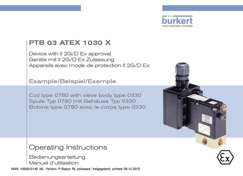
Burkert AirLINE Ex 8650 User manual

Operating Instructions
Bedienungsanleitung
Instructions de Service
Type 8650
AirLINE Ex
Electrical and Pneumatic Automation System

We reserve the right to make technical changes without notice.
Technische Änderungen vorbehalten.
Sous resérve de modification techniques.
© 2006 - 2016 Bürkert Werke GmbH
Operating Instructions 1601/06_EU-EN_00804032

3
GENERAL INFORMATION AND SAFETY INSTRUCTIONS ....................................................................................................5
1. Operating Instructions ........................................................................................................................................................6
2. Intended Use ............................................................................................................................................................................7
3. Basic safety instructions ....................................................................................................................................................8
4. General Information...........................................................................................................................................................10
SYSTEM DESCRIPTION ...........................................................................................................................................................................11
1. General Description ...........................................................................................................................................................12
2. Technical Data .....................................................................................................................................................................15
3. System Accessories ..........................................................................................................................................................17
CONFIGURATION AND FUNCTION ...................................................................................................................................................19
1. Configuration .........................................................................................................................................................................20
2. Function ...................................................................................................................................................................................25
CONFIGURATION AND FUNCTION OF THE MODULES ......................................................................................................27
1. Supply Segments ...............................................................................................................................................................29
2. Valve segments ....................................................................................................................................................................34
3. Pneumatic Connector Module .....................................................................................................................................41
4. Basic Pneumatic Module ................................................................................................................................................43
5. Terminal module ..................................................................................................................................................................46
6. Electronic Module ...............................................................................................................................................................48
7. Valve that can be integrated .........................................................................................................................................51
INSTALLATION ...............................................................................................................................................................................................57
1. Safety Instructions .............................................................................................................................................................59
2. Installation Instructions ...................................................................................................................................................61
3. Installation on S7 Profile Rail (Pre-assembled System) ...............................................................................63
4. Installation in the control cabinet ...............................................................................................................................65
5. Configuration, Conversion and Expansion of an existing system with
individual segments ..........................................................................................................................................................66
6. Removal / Installation of individual Segments ...................................................................................................68
7. Removal / Installation of the Cover flaps ..............................................................................................................70
Electrical and Pneumatic Automation System Type 8650
Type 8650
english
Contents

4
8. Replacing a terminal or pneumatic module .........................................................................................................71
9. Replacing a valve ................................................................................................................................................................72
10. Connection of the Air Inlet and Exhaust Lines ...................................................................................................73
COMMISSIONING ........................................................................................................................................................................................75
1. Safety Instructions .............................................................................................................................................................76
2. Initialization ............................................................................................................................................................................77
3. SD Card / System Serialization Data ......................................................................................................................99
MAINTENANCE AND REPAIR ............................................................................................................................................................101
1. Safety Instructions ..........................................................................................................................................................102
2. Maintenance ....................................................................................................................................................................... 103
3. Maintenance ....................................................................................................................................................................... 104
STORAGE, PACKAGING, TRANSPORT, DISPOSAL ............................................................................................................ 107
1. Storage .................................................................................................................................................................................. 108
2. Packaging, Transport ..................................................................................................................................................... 110
ANNEX ............................................................................................................................................................................................................. 111
1. EC Declaration of Conformity ....................................................................................................................................112
2. EC-Type Examination Certificate Terminal modules ..................................................................................... 118
3. IEC-Ex Certificate of Conformity Terminal modules .....................................................................................120
4. EC-Type Examination Certificate Electronic modules ..................................................................................123
5. IEC-Ex Certificate of Conformity Electronic modules ..................................................................................126
6. EC-Type-Examination certificate 11 mm-Valves Type 6104 ..................................................................... 129
7. IEC-Ex Certificate of Conformity 11 mm-Valves Type 6104 ..................................................................... 133
8. EC-Type-Examination Certifcate 16,5 mm-Valves Type 6106 .................................................................. 136
9. IEC-Ex Certificate of Conformity 16,5 mm-Valves Type 6106 ................................................................. 140
10. EC-Type-Examintation Certificate 11 mm-Valves Type 6144 ................................................................... 143
11. IEC-Ex Certificate of Conformity 11 mm-Valves Type 6144 ..................................................................... 149
Type 8650
english
Contents

5
General Information and Safety Instructions
Contents
1. OPERATING INSTRUCTIONS ........................................................................................................................................................6
1.1. Symbols ......................................................................................................................................................................................6
2. INTENDED USE ....................................................................................................................................................................................7
2.1. Restrictions ...............................................................................................................................................................................7
3. BASIC SAFETY INSTRUCTIONS .................................................................................................................................................8
4. GENERAL INFORMATION .............................................................................................................................................................10
4.1. Contact address ..................................................................................................................................................................10
4.2. Warranty ...................................................................................................................................................................................10
4.3. Approvals ................................................................................................................................................................................10
4.4. Information on the Internet ............................................................................................................................................10
4.5. Trademarks ............................................................................................................................................................................10
Type 8650
english
Allgemeine Informationen
Sicherheitshinweise

6
1. OPERATING INSTRUCTIONS
The operating instructions describe the entire life cycle of the device. Keep these instructions in a location which is easily
accessible to every user and make these instructions available to every new owner of the device.
WARNING!
The operating instructions contain important safety information!
Failure to observe these instructions may result in hazardous situations.
• The operating instructions must be read and understood.
1.1. Symbols
DANGER!
Warns of an immediate danger!
• Failure to observe the warning may result in a fatal or serious injury.
WARNING!
Warns of a potentially dangerous situation!
• Failure to observe the warning may result in serious injuries or death.
CAUTION!
Warns of a possible danger!
• Failure to observe this warning may result in a moderately severe or minor injury.
NOTE!
Warns of damage to property!
1. Failure to observe the warning may result in damage to the device or the equipment.
designates additional significant information, tips and recommendations.
refers to information in these operating instructions or in other documentation.
→designates a procedure which you must carry out.
Type 8650
english
Allgemeine Informationen
Sicherheitshinweise

7
2. INTENDED USE
Incorrect use of the Type 8650 AirLINE Ex can be dangerous to people, nearby equipment and the
environment.
• The device is designed for use in explosive environments (precise classification see EC-Type Examination
Certificates in the Appendix). It may be used to control pneumatically operated devices.
• Ensure that the device is protected before using outdoors.
• Use according to the authorized data, operating conditions and conditions of use specified in the contract
documents and operating instructions. These are described in the chapter entitled “System Description Air-
LINE Ex” and “Technical Data”.
• The device may be used only in conjunction with third-party devices and components recommended and
authorised by Bürkert.
• Correct transportation, correct storage and installation and careful use and maintenance are essential for reli-
able and faultless operation.
• Use the Type 8650 AirLINE Ex 8793 only as intended.
The AirLINE Ex system Type 8650 was developed with due consideration given to accepted safety rules
and is state-of-the-art. Nevertheless, dangerous situations may occur.
2.1. Restrictions
If exporting the system/device, observe any existing restrictions.
2.1.1. Ex-Approval
The Ex approval is only valid if the modules and components approved by Bürkert are used in the manner
described in this operating manual.
The electronic modules may only be employed in combination with the pneumatic valve types approved by
Bürkert. Use in any other way will invalidate the Ex approval!
Unauthorized modifications to the system, the modules or components will also void the Ex approval.
Type 8650
english
Allgemeine Informationen
Sicherheitshinweise

8
3. BASIC SAFETY INSTRUCTIONS
These safety instructions do not make allowance for any
• contingencies and events which may arise during the installation, operation and maintenance of the devices.
• local safety regulations; the operator is responsible for observing these regulations, also with reference to the
installation personnel.
Danger – high pressure!
• Before loosening the lines and valves, turn off the pressure and vent the lines.
Risk of electric shock!
• Before reaching into the device or the equipment, switch off the power supply and secure to prevent
reactivation!
• Observe applicable accident prevention and safety regulations for electrical equipment!
(It is permitted to replace electronic modules and valves even while the power is on.)
Verbrennungsgefahr/Brandgefahr bei Dauerbetrieb durch heiße Geräteoberfläche!
• Das Gerät von leicht brennbaren Stoffen und Medien fernhalten und nicht mit bloßen Händen berühren.
General hazardous situations.
To prevent injury, ensure that:
• Do not supply aggressive or inflammable media to the media connections of the system.
• Do not supply fluids to the media connections of the system.
• In low-pressure applications ensure that no flammable or explosive media are drawn into the AirLINE-Ex system.
• Do not subject the housing to mechanical loads (e. g. by placing objects on the housing or using the
housing as a step).
• Do not cover the ventilation slots in the housing.
• The system cannot be activated unintentionally.
• Installation and repair work may be carried out by authorised technicians only and with the appropriate tools.
• After an interruption in the power supply or pneumatic supply, ensure that the process is restarted in a
defined or controlled manner.
• The device may be operated only when in perfect condition and in consideration of the operating instructions.
• The general rules of technology apply to application planning and operation of the device.
Type 8650
english
Allgemeine Informationen
Sicherheitshinweise

9
NOTE!
Operate the system with direct current only!
To avoid damaging the system, use only direct current as the power supply for the system.
Avoid pressure drop!
To avoid a pressure drop, the compressed air supply to the system must be as large as possible.
Electrostatic sensitive components / modules!
• The device contains electronic components which react sensitively to electrostatic discharge (ESD). Contact
with electrostatically charged persons or objects is hazardous to these components. In the worst case scenario,
they will be destroyed immediately or will fail after start-up.
• Observe the requirements in accordance with EN 61340-5-1 to minimise or avoid the possibility of damage
caused by sudden electrostatic discharge!
• Also ensure that you do not touch electronic components when the power supply voltage is present!
Type 8650
english
Allgemeine Informationen
Sicherheitshinweise

10
4. GENERAL INFORMATION
4.1. Contact address
Germany
Bürkert Fluid Control System
Sales Centre
Chr.-Bürkert-Str. 13-17
D-74653 Ingelfingen
Tel. + 49 (0) 7940 - 10-91 111
Fax + 49 (0) 7940 - 10-91 448
E-mail: [email protected]
International
Contact addresses can be found on the final pages of these operating instructions.
And also on the internet at:
www.buerkert.com
4.2. Warranty
The warranty is only valid if the AirLINE Ex Type 8650 is used as authorized in accordance with the specified appli-
cation conditions.
4.3. Approvals
The approval rating on the Bürkert labels refers to Bürkert products.
You can find more detailed information on the approvals in the Appendix of these operating instructions.
4.4. Information on the Internet
The operating instructions and data sheets for Type 8650 can be found on the Internet at:
www.buerkert.com Type 8650
4.5. Trademarks
The listed designations are trademarks of the respective companies / associations / organizations.
ET 200iSP Siemens AG
PROFIBUS PROFIBUS Nutzerorganisation e. V.
Type 8650
english
Allgemeine Informationen
Sicherheitshinweise

11
System Description
Contents
1. GENERAL DESCRIPTION .............................................................................................................................................................12
1.1. Product Description ...........................................................................................................................................................12
1.2. Characteristic Features and Benefits ......................................................................................................................13
1.3. Field of Application ............................................................................................................................................................14
1.4. Marking ...................................................................................................................................................................................14
2. TECHNICAL DATA ...........................................................................................................................................................................15
2.1. General Technical Data ....................................................................................................................................................15
2.2. Dimensions ............................................................................................................................................................................16
3. SYSTEM ACCESSORIES ..............................................................................................................................................................17
Type 8650
english
System Description

12
1. GENERAL DESCRIPTION
1.1. Product Description
AirLINE Ex Type 8650 (hereafter referred to as AirLINE Ex) is an electrical and pneumatic automation system in
protection class IP30 that has been developed for use in explosive environments.
In combination with modules from the Siemens SIMATIC ET 200iSP System, a full range of electronic and pneu-
matic components are available. As long as simple rules are observed, it permits pneumatic, electric and elec-
tronic modules with different functions can be combined with one another. The components are connected to
each other using screws or latches. In this way both the electrical and the pneumatic connections are made.
The pilot valves integrated on the pneumatic modules allow a wide range of different pneumatic actuators to be
controlled on site (e. g. process valves or pneumatic cylinders).
Fig. 1: View of the overall system
(Siemens SIMATIC ET 200iSP and
Bürkert AirLINE Ex)
Fig. 2: View of the Bürkert AirLINE Ex system
Type 8650
english
System Description

13
1.2. Characteristic Features and Benefits
1.2.1. Characteristic features of AirLINE Ex
• Simple operation
• Automatic set-up of supply and data circuits
• Open, flexible and modular structure
• Combination of different valve segments and different electrical I/O functions for space and application-opti-
mized station configurations.
• Seamless integration into Siemens SIMATIC ET 200iSP
• Operation is possible with oiled or unoiled compressed air, as well as with neutral and non-combustible gases.
1.2.2. The benefits of AirLINE Ex
• Flow-optimized valve design.
Pressure range of vacuum up to 10 bar (depending on the valve models used).
Flow of approx. 300 l/min and 700 l/min for a valve width of 10 mm and 16 mm respectively.
• Long service life with oiled and unoiled compressed air thanks to low-wear valve function.
• Central exhaust air exhaust.
• Replacement of valves and electronic modules during operation possible thanks to „intrinsically safe“
explosion-proof construction.
• Optional operation with auxiliary control air in extended pressure ranges (also see the chapter Configuration
and Function of the Modules / Integratable Valves)
• Simple combination of various functions, configurations and add-ons thanks to high modularity
• Numerous valve functions: 3/2-, 2 x 3/2- and 5/2-way combined with various circuit functions
• Wide range of connection possibilities
• Integration of pneumatic options possible (e. g. check valves)
• Optional emergency manual override of the valves
• Different pressure levels possible in one system
• Integration of pressure gauges for operating pressure display
• Central compressed air supply
Type 8650
english
System Description

14
1.3. Field of Application
The AirLINE Ex System is designed for decentralized operation in industrial environments.
Thanks to the modular configuration, electronics and fluidics can be combined particularly simply and efficiently.
It complies with protection class IP30.
DANGER!
Risk of electric shock!
The terminal modules (with upright system wiring) are designed for the Ex-protection class “Ex-e” (increased
safety).
• Before working on the terminal modules, always switch off the operating voltage to the system.
Further information can be found in the handbook for the Siemens ET200iSP.
Danger of explosion!
If a system is installed in a control cabinet in the explosion-proof area, observe the following:
• The control cabinet must be authorized for use in the explosion-protected area.
• The control cabinet must be dimensioned large enough to ensure that the generated lost heat can be dissi-
pated to the exterior in a suitable manner.
• The internal temperature of the control cabinet must not exceed the max. permitted ambient temperature for
the device.
1.4. Marking
Type 8650
Ident no. 001xxxxxx
Serial no. 00001123
Fig. 3: Location of the type label Fig. 4: Type label
Information about the labeling of the electronic and terminal modules can be found in the chapters
Configuration and Function of the Modules / Terminal Module / Labeling and
Configuration and Function of the Modules / Electronic Module / Labeling.
Type 8650
english
System Description

15
2. TECHNICAL DATA
2.1. General Technical Data
Medium Clean, dry air (oiled or unoiled),
neutral gases (particle size max. 5 μm)
Max. power consumption see table below “Power consumption of the active
modules”.
Ambient temperature during
operation
0 °C to +55 °C
Storage temperature -20 °C to +60 °C
Relative humidity 5 to 95 %, non-condensing
Acceleration during operation 5 m/s2
Rated operating mode 100 % CDF ( continuous operation)
Operating voltage 24 V DC in EEx-e
(Details: see Siemens Power Supply Module)
Degree of protection IP30
Protection class 3 (VDE0580)
Housing materials Pneumatic modules and valves: PA (polyamide
electronic modules: PBT (polybutylene terephthalate)
Seal materials Pneumatic modules and valves: NBR
electronic modules: PC (polycarbonate)
Approvals A prerequisite for the authorized use of the total AirLINE-Ex system is the
installation in a suitable certified housing:
- Ex-e- or Ex-d-housing for Zone 1 respectively
- Ex-d-housing for Zone 21
FA prerequisite for FM-Ex in Zone 21 or Class II, III Div. 1,2 with the sub-
stance classes E, F & G is the operation in a suitable Ex-D housing.
• Electronic modules ATEX: ATEX II 2 G Ex ib IIC T4 (Zone 1 / 21)
IEC-Ex: IECEx KEM 07.0032
FM-Ex: Class II, III, Div. 1, 2, GP E, F, G
IS Class I, Div. 1 GP A, B, C, D T4
Class I, Div. 2 GP A, B, C, D T4
Class I, Zone 1, AEx ib IIC T4
• Terminal modules ATEX: ATEX II 2 G Ex e [ia/ib] IIC T4 (Zone 1 / 21)
IEC-Ex: IECEx KEM 07.0033
FM-Ex: Class II, III, Div. 1, 2, GP E, F, G
IS Class I, Div. 1, GP A, B, C, D T4
Class I, Div 2, GP A, B, C, D T4
Class I, Zone 1 e [ia/ib] IIC T4
The AirLINE Ex satisfies the requirements of the EMC Act.
Interference resistance EN 50082-2
Emitted interference EN 50081-2
Type 8650
english
System Description

16
2.1.1. Power consumption of the active modules, including the
mounted valves
Modul type max. power consumption Ident-no.
4 channels 11 mm max. 2.9 W 171 941
8 channels 11 mm max. 3.6 W 171 942
4 channels 16,5 mm max. 2.9 W 171 943
8 channels 16,5 mm max. 3.6 W 171 944
2.2. Dimensions
2.2.1. The Complete System
165
27,7
17
31,5
56
12,5
28,5
10,5 8,25
16,5
3 x
16,5 (=49,5)
5,5 11
3 x
11(=33)
24
12,5
28,5
88 + ( n x 44 + n x 66 )
44 44
35 190
66 44
33
Plug-in coupling D6
Screw socket M5 + M7
Plug-in coupling D8; 5/16
Screw socket G1/8 + NPT 1/8
Screw socket G3/8 + G1/8; NPT 3/8 + NPT 1/8
Connections optinally
Siemens S7
Profile rail
6ES7390
nx44 = Number of modules overall width 44 mm
nx66 = Number of modules overall width 66 mm
Fig. 5: Dimensions [mm] - The Complete System
Type 8650
english
System Description

17
3. SYSTEM ACCESSORIES
System accessories Ident-no.
Function plates for flange pattern 6524 / 6525
(Installation instead of a simple 3/2-way or 5/2-way valve / 11 mm)
Blind plate complete for 3/2-way and 5/2-way valves
(for sealing an unused valve position)
650 373
Supply plate complete)
(for additional medium supply for high-consumption applications or for supplying separate media
circuits or pressure stages)
649 637
Breather plate complete)
(for additional exhaust for high-consumption applications or for exhaust of separate media circuits
or pressure stages)
655 166
Function plates for flange pattern 6524
(installation instead of a 2x 3/2-way valve / 11 mm)
Blind plate complete for 2x 3/2-way valves
(for sealing an unused valve position)
661 092
Supply plate complete 1)
(for additional medium supply for high-consumption applications or for feeding separate media
circuits or pressure stages)
667 945
Breather plate complete 1)
(for additional exhaust for high-consumption applications or for exhaust of separate media circuits
or pressure stages)
667 947
Function plates for flange pattern 6526 / 6527
(Installation instead of a 3/2-way or 5/2-way valve / 16.5 mm)
Blind plate complete for 3/2-way and 5/2-way valve 653 765
Supply plate complete
(for additional medium supply for high-consumption applications or for feeding separate media
circuits or pressure stages)
655 156
Breather plate complete
(for additional exhaust for high-consumption applications or for exhaust of separate media circuits
or pressure stages)
653 697
Further accessories
Set with various spare parts for valve and module installation (seals, screws, etc.) 186 877
Cap for plug-in valve contact 653 670
Plug for P channel shut-off (for configuration of several pressure stages or media circuits in a
system, Type 8650)
655 068
S7-Profile rail, lenght 482 mm 6ES7390-1AE80-0AA0 (Siemens) 655 982
S7-Profile rail, lenght 530 mm 6ES7390-1AF30-0AA0 (Siemens) 655 983
S7-Profile rail, lenght 585 mm 6ES7390-1AF85-0AA0 (Siemens) 671 701
S7-Profile rail, lenght 830 mm 6ES7390-1AJ30-0AA0 (Siemens) 671 702
S7-Profile rail, lenght 885 mm 6ES7390-1AJ85-0AA0 (Siemens) 671 703
S7-Profile rail, lenght 2000 mm 6ES7390-1BC00-0AA0 (Siemens) --
Suitable Ex bus connector for Siemens IM152 e. g. 6ES7-972-0DA60-0XA0 (Siemens) 655 981
Type 8650
english
System Description

18
1) These plates are installed instead of a valve and use the working ports of the respective valve position.
As these have smaller cross-sections than the ports on the supply segments, the possible flow rates are cor-
respondingly lower!
For competent advice, please contact your local Bürkert sales partner.
Type 8650
english
System Description

19
Configuration and Function
Contents
1. CONFIGURATION .............................................................................................................................................................................20
1.1. Maximum System Configuration ................................................................................................................................20
1.2. Siemens SIMATIC ET 200iSP System Components ........................................................................................21
1.3. Bürkert AirLINE Ex - System Components ...........................................................................................................21
2. FUNCTION ............................................................................................................................................................................................25
2.1. View of the Overall System ...........................................................................................................................................25
2.2. Functional representation of the AirLINE Ex-system ......................................................................................26
Type 8650
english
Configuration and Function

20
1. CONFIGURATION
1.1. Maximum System Configuration
No. of modules up to 32 I/O modules / pneumatic modules
in the complete system Siemens SIMATIC ET 200iSP / Bürkert AirLINE Ex
At least 1 field bus interface module (IM152) and 1 power supply module each;
if required, these can be installed redundantly.
Valve positions up to 48 with 11 mm valves Types 6524/6525 (with a middle supply segment)
up to 32 with 16.5 mm valves Types 6526/6527 (with a middle supply segment)
Mixing 44 mm / 66 mm valve segments is possible.
Maximum width 1095 mm including all Siemens modules (one power supply and one interface)
1185 mm including all Siemens modules (two power supply and two interfaces)
Other limitations are possible due to the installation position and power considerations (see the Simatic ET
200iSP manual).
Type 8650
english
Configuration and Function
Other manuals for AirLINE Ex 8650
1
Table of contents
Other Burkert Industrial Electrical manuals
Popular Industrial Electrical manuals by other brands

Vega
Vega VEGATOR 122 operating instructions

LEGRAND
LEGRAND Celiane 670 91 Quick installation guide

Murata
Murata GRM188C80J225ME19 Series Reference sheet

Bticino
Bticino Legrand MyHOME Up installation manual

Smith Manufacturing
Smith Manufacturing X3 user manual

Murata
Murata GRT32DR60J226KE01 Series Reference sheet