BUSCH Samos SE 0085 D User manual

Installation and
Operating Instructions
Side Channel Blowers
Samos SE 0045 - 1105 D/D2
Busch Produktions GmbH
Schauinslandstr. 1
79689 Maulburg
Germany
0870133372 / 100512 / Original instructions / Modifications reserved

Table of Contents
Preface . . . . . . . . . . . . . . . . . . . . . . . . . . . . . . . 2
Product Description. . . . . . . . . . . . . . . . . . . . . . . . . 3
Use . . . . . . . . . . . . . . . . . . . . . . . . . . . . . . . . 3
Principle of Operation . . . . . . . . . . . . . . . . . . . . . . 3
Cooling . . . . . . . . . . . . . . . . . . . . . . . . . . . . . . 3
Start Controls. . . . . . . . . . . . . . . . . . . . . . . . . . . 3
Safety . . . . . . . . . . . . . . . . . . . . . . . . . . . . . . . . 3
Intended Use . . . . . . . . . . . . . . . . . . . . . . . . . . . 3
Safety Notes . . . . . . . . . . . . . . . . . . . . . . . . . . . 3
Noise Emission . . . . . . . . . . . . . . . . . . . . . . . . . . 3
Transport . . . . . . . . . . . . . . . . . . . . . . . . . . . . . . 4
Transport in Packaging . . . . . . . . . . . . . . . . . . . . . . 4
Transport without Packaging . . . . . . . . . . . . . . . . . . . 4
Storage . . . . . . . . . . . . . . . . . . . . . . . . . . . . . . . 4
Short-term Storage . . . . . . . . . . . . . . . . . . . . . . . . 4
Conservation . . . . . . . . . . . . . . . . . . . . . . . . . . . 4
Installation and Commissioning . . . . . . . . . . . . . . . . . . 4
Installation Prerequisites . . . . . . . . . . . . . . . . . . . . . 4
Mounting Position and Space . . . . . . . . . . . . . . . . . 5
Suction Connection/Gas Inlet . . . . . . . . . . . . . . . . . 5
Gas Discharge . . . . . . . . . . . . . . . . . . . . . . . . . 5
Pressure Connection . . . . . . . . . . . . . . . . . . . . . . 5
Electrical Connection / Controls . . . . . . . . . . . . . . . . 6
Controlling Pressure/Flow . . . . . . . . . . . . . . . . . . . 6
Installation . . . . . . . . . . . . . . . . . . . . . . . . . . . . 6
Mounting . . . . . . . . . . . . . . . . . . . . . . . . . . . 6
Connecting Electrically . . . . . . . . . . . . . . . . . . . . . 6
Connection Scheme Alternating Current Motor . . . . . . . 6
Connection Scheme Three-Phase Motor. . . . . . . . . . . 6
Setting the Relief Valve . . . . . . . . . . . . . . . . . . . . 7
Connecting Lines/Pipes . . . . . . . . . . . . . . . . . . . . 7
Recording of Operational Parameters . . . . . . . . . . . . . 7
Operation Notes . . . . . . . . . . . . . . . . . . . . . . . . . 7
Use . . . . . . . . . . . . . . . . . . . . . . . . . . . . . . 7
Maintenance . . . . . . . . . . . . . . . . . . . . . . . . . . . . 8
Maintenance Schedule . . . . . . . . . . . . . . . . . . . . . . 8
Monthly: . . . . . . . . . . . . . . . . . . . . . . . . . . 8
Every 6 Months: . . . . . . . . . . . . . . . . . . . . . . 8
Every Year: . . . . . . . . . . . . . . . . . . . . . . . . . 8
Overhaul . . . . . . . . . . . . . . . . . . . . . . . . . . . . . . 8
Removal from Service. . . . . . . . . . . . . . . . . . . . . . . . 9
Temporary Removal from Service. . . . . . . . . . . . . . . . . 9
Recommissioning . . . . . . . . . . . . . . . . . . . . . . . . . 9
Dismantling and Disposal . . . . . . . . . . . . . . . . . . . . . 9
Troubleshooting . . . . . . . . . . . . . . . . . . . . . . . . . . 10
Exploded Views and Spare Parts Lists . . . . . . . . . . . . . . . 13
SE 0045 - 0315 D . . . . . . . . . . . . . . . . . . . . . . . . 13
SE 0535 - 1105 D . . . . . . . . . . . . . . . . . . . . . . . . 15
SE 0085 - 0315 D2 . . . . . . . . . . . . . . . . . . . . . . . 17
EC-Declaration of Conformity . . . . . . . . . . . . . . . . . . . 19
Technical Data. . . . . . . . . . . . . . . . . . . . . . . . . . . 20
Busch – All over the World in Industry . . . . . . . . . . . . . . 21
SE 0045 - 1105 D/D2 Preface
0870133372 / 100512 page 2
Preface
Congratulations on your purchase of the Busch side channel blower.
With watchful observation of the field’s requirements, innovation and
steady development Busch delivers modern vacuum and pressure solu-
tions worldwide.
These operating instructions contain information for
–product description,
–safety,
–transport,
–storage,
–installation and commissioning,
–maintenance,
–overhaul,
–troubleshooting and
–spare parts
of the side channel blower.
For the purpose of these instructions, “handling” the side channel
blower means the transport, storage, installation, commissioning, influ-
ence on operating conditions, maintenance, troubleshooting and over-
haul of the side channel blower.
Prior to handling the side channel blower these operating instructions
shall be read and understood. If anything remains to be clarified
please contact your Busch representative!
Keep these operating instructions and, if applicable, other pertinent
operating instructions available on site.

Product Description
Use
The side channel blower is intended for
–the suction
–the compression
of
–air and other dry, non-aggressive, non-toxic and non-explosive
gases
Conveying media with a lower or higher density than air leads to an in-
creased thermal and/or mechanical load on the side channel blower
and is permissible only after prior consultation with Busch.
The gas shall be free from vapours that would condensate under the
temperature and pressure conditions inside the side channel blower.
The side channel blower is intended for the placement in a non-poten-
tially explosive environment.
The side channel blower is suitable for continuous operation, provided
that the housing can transmit heat to the environment without ob-
struction and a certain minimum gas transfer is warranted. If there is a
risk that the side channel blower may be operated against a closed inlet
or outlet for more than a few seconds, a vacuum or pressure relief
valve, respectively, shall be provided. Frequent switching on and off
leads to increased coil temperatures. In case of doubt seek advice from
your Busch representative!
The maximum allowed pressure on the pressure connection (d) is
2 bar abs. By means of process control and/or pressure relief valves it
must be made sure that the maximum allowed pressure will not be
exceeded.
Principle of Operation
The side channel blower works on the impulse principle, i.e. kinetic en-
ergy is transferred from the rotor to the conveyed medium and then is
converted into pressure.
For the two stage version:
2 stages, both working on the principle described above, are installed
in line in order to achieve a better ultimate/differential pressure.
The side channel blower compresses the inlet gas absolutely oil-free.
A lubrication of the pump chamber is neither necessary nor allowed.
Cooling
The side channel blower is cooled by
–radiation of heat from the surface of the side channel blower
–the air flow from the fan wheel of the drive motor
–the process gas
Start Controls
The side channel blower comes without start controls. The control of
the side channel blower is to be provided in the course of installation.
Safety
Intended Use
Definition: For the purpose of these instructions, “handling” the side
channel blower means the transport, storage, installation, commission-
ing, influence on operating conditions, maintenance, troubleshooting
and overhaul of the side channel blower.
The side channel blower is intended for industrial use. It shall be han-
dled only by qualified personnel.
The allowed media and operational limits (Úpage 3: Product De-
scription) and the installation prerequisites (Úpage 4: Installation
Prerequisites) of the side channel blower shall be observed both by
the manufacturer of the machinery into which the side channel blower
is to be incorporated and by the operator.
The maintenance instructions shall be observed.
Prior to handling the side channel blower these installation and oper-
ating instructions shall be read and understood. If anything remains
to be clarified please contact your Busch representative!
Safety Notes
The side channel blower has been designed and manufactured accord-
ing to state-of-the-art methods. Nevertheless, residual risks may re-
main. These operating instructions highlight potential hazards where
appropriate. Safety notes are tagged with one of the keywords
DANGER, WARNING and CAUTION as follows:
DANGER_a
Disregard of this safety note will always lead to accidents with fa-
tal or serious injuries.
WARNING_a
Disregard of this safety note may lead to accidents with fatal or se-
rious injuries.
CAUTION_a
Disregard of this safety note may lead to accidents with minor inju-
ries or property damage.
Noise Emission
For the sound pressure level in free field according to EN ISO 2151
Úpage 20: Technical Data.
SE 0045 - 1105 D/D2 Product Description
0870133372 / 100512 page 3
a Terminal box
b Housing
c Inlet
d Gas discharge/ pressure
connection

CAUTION_a4
Depending on the construction size the side channel blower can
emit noise of high intensity.
Depending on the operating state the side channel blower can emit
noise in a narrow band.
Risk of damage to the hearing.
Persons staying in the vicinity of a non noise insulated side channel
blower over extended periods shall wear ear protection.
Transport
Transport in Packaging
Side channel blowers individually packed in cardboard boxes can be
carried by hand.
Packed on a pallet the side channel blower is to be transported with a
forklift.
Transport without Packaging
In case the side channel blower is packed in a cardboard box with in-
flated cushions:
◆Remove the inflated cushions from the box
In case the side channel blower is in a cardboard box cushioned with
rolled corrugated cardboard:
◆Remove the corrugated cardboard from the box
In case the side channel blower is laid in foam:
◆Remove the foam
In case the side channel blower is bolted to a pallet or a base plate:
◆Remove the bolting between the side channel blower and the
pallet/base plate
In case the side channel blower is fastened to the pallet by means of
tightening straps:
◆Remove the tightening straps
In case the side channel blower weighs less than 20 kg and comes
without eyebolts for the attachment of lifting gear:
Version without handle:
◆Grasp the side channel blower with both hands
Version with handle:
◆Carry the side channel blower using the handle
In case the side channel blower comes with one or more eyebolts for
the attachment of lifting gear:
CAUTION_af
Do not walk, stand or work under suspended loads.
●Make sure that the eyebolt is in faultless condition (replace a dam-
aged, e.g. bent eyebolt with a new one)
●Make sure that the eyebolt is fully screwed in and tightened by
hand
●Attach lifting gear securely to the eyebolt on the cylinder
●Attach the lifting gear to a crane hook with safety latch
●Lift the side channel blower with a crane
In case the side channel blower was bolted to a pallet or a base plate:
◆Remove the stud bolts from the rubber feet
Storage
Short-term Storage
●Make sure that the suction connection/gas inlet and the gas dis-
charge/pressure connection are closed (leave the provided plugs
in)
●Store the side channel blower
–if possible in original packaging,
–indoors,
–dry,
–dust free and
–vibration free
Conservation
In case of adverse ambient conditions (e.g. aggressive atmosphere, fre-
quent temperature changes) conserve the side channel blower immedi-
ately. In case of favourable ambient conditions conserve the side
channel blower if a storage of more than 3 months is scheduled.
●Make sure that all ports are firmly closed; seal all ports that are not
sealed with PTFE-tape, gaskets or o-rings with adhesive tape
Note: VCI stands for “volatile corrosion inhibitor”. VCI-products (film,
paper, cardboard, foam) evaporate a substance that condenses in mo-
lecular thickness on the packed good and by its electro-chemical prop-
erties effectively suppresses corrosion on metallic surfaces. However,
VCI-products may attack the surfaces of plastics and elastomers. Seek
advice from your local packaging dealer! Busch uses CORTEC
VCI 126 R film for the overseas packaging of large equipment.
●Wrap the side channel blower in VCI film
●Store the side channel blower
–if possible in original packing,
–indoors,
–dry,
–dust free and
–vibration free.
For commissioning after conservation:
●Make sure that all remains of adhesive tape are removed from the
ports
●Commission the side channel blower as described in the chapter
Installation and Commissioning (Úpage 4)
Installation and
Commissioning
Installation Prerequisites
CAUTION_a
In case of non-compliance with the installation prerequisites, partic-
ularly in case of insufficient cooling:
Risk of damage or destruction of the side channel blower and ad-
joining plant components!
Risk of injury!
The installation prerequisites must be complied with.
●Make sure that the integration of the side channel blower is carried
out such that the essential safety requirements of the Machine Di-
rective 2006/42/EC are complied with (in the responsibility of the
designer of the machinery into which the side channel blower is to
be incorporated; Úpage 19: note in the EC-Declaration of Con-
formity)
SE 0045 - 1105 D/D2 Transport
0870133372 / 100512 page 4

Mounting Position and Space
●Make sure that the environment of the side channel blower is not
potentially explosive
●Make sure that the following ambient conditions will be complied
with:
–ambient temperature: –5 ... +40 °C
–ambient pressure: atmospheric
●Make sure that the environmental conditions comply with the pro-
tection class of the drive motor (according to the nameplate)
The side channel blower can be operated with horizontal or vertical gas
flow (with vertical gas flow the drive motor shall be in the uppermost
position)
●Make sure that the mounting base is even
●Make sure that in order to warrant a sufficient cooling there will be
a clearance of minimum 0.1 m between the side channel blower
and nearby walls
●Make sure thate there will a clearance of minimum 3.5 cm (up to
construction size 140) or 5.5 cm (as of constructions size 200) be-
tween the fan hood and nearby walls/ceiling
●Make sure that there will be a clearance of minimum 2 cm (up to
construction size 200), 3 cm (for construction size 310) or 4 cm (as
of constructions size 530), respectively, between the cover (70)
and nearby walls/floor
In case of mounting with the drive motor in the uppermost position:
◆Provide vibration insulating rubber feet to fasten the side
channel blower to the floor
●Make sure that no heat sensitive parts (plastics, wood, cardboard,
paper, electronics) will touch the surface of the side channel
blower
●Make sure that the installation space or location is vented such
that a sufficient cooling of the side channel blower is warranted
CAUTION_ac
During operation the surface of the side channel blower may reach
temperatures of more than 70 °C.
Risk of burns!
●Make sure that the side channel blower will not be touched inad-
vertently during operation, provide a guard if appropriate
Suction Connection/Gas Inlet
CAUTION_a
Intruding foreign objects or liquids can destroy the side channel
blower.
In case the inlet gas can contain dust or other foreign solid particles:
◆Make sure that a suitable filter (5 micron or less) is installed
upstream the side channel blower
In case of compressor operation:
The following guidelines for the suction line do not apply, if the air
to be compressed is taken in right at the side channel blower.
●Make sure that the suction line fits to the suction connection/gas
inlet (c) of the side channel blower
●Make sure that the gas will be sucked through a vacuum-tight
flexible hose or a pipe
In case of using a pipe:
◆Make sure that the pipe will cause no stress on the side
channel blower’s connection, if necessary use an expansion
joint
●Make sure that the line size of the suction line over the entire
length is at least as large as the suction connection/gas inlet (c) of
the side channel blower
In case the length of the suction line exceeds 2 m it is prudent to use
larger line sizes in order to avoid a loss of efficiency and an overload of
the side channel blower. Seek advice from your Busch representative!
In case the vacuum shall be maintained after shutdown of the side
channel blower:
◆Provide a manual or automatic operated valve (= non-return
valve) in the suction line
●Make sure that the suction line does not contain foreign objects,
e.g. welding scales
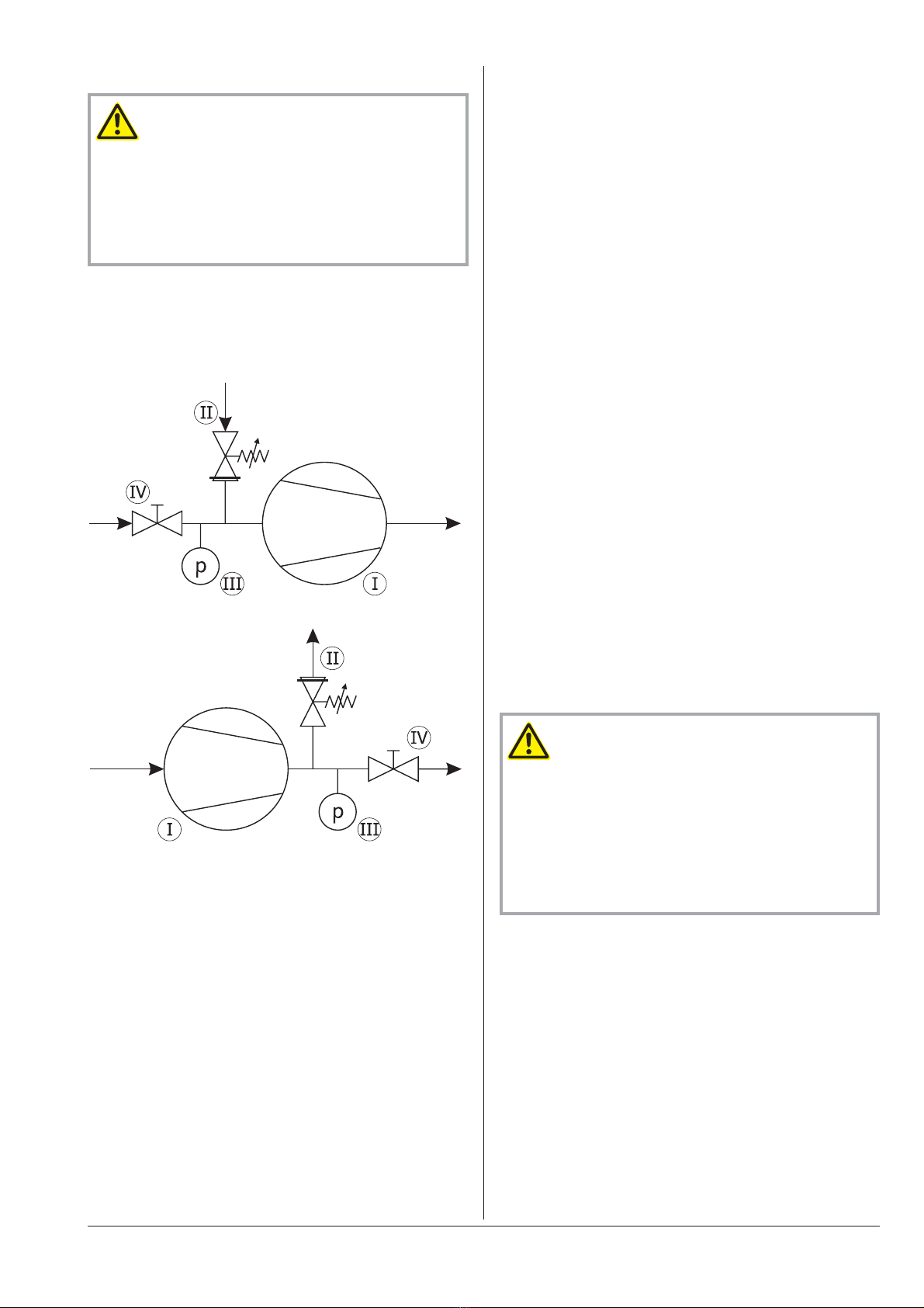
In case the side channel blower will be used for vacuum application
and is likely to run against a closed inlet for more than a few seconds:
◆Provide a vacuum relief valve and set it to approx. 75 percent
of the max. differential pressure
In case of doubt seek advice from your Busch representative!
Gas Discharge
In case of vacuum operation:
The discharged gas must flow without obstruction. It is not per-
mitted to shut off or throttle the discharge line or to use it at as a
pressurised air source.
In case of vacuum operation:
The following guidelines for the discharge line do not apply, if the
aspirated air is discharged to the environment right at the side
channel blower.
●Make sure that the discharge line fits to the gas discharge (d) of
the side channel blower
In case of using a pipe:
◆Make sure that the pipe will cause no stress on the side
channel blower’s connection, if necessary use an expansion
joint
●Make sure that the line size of the discharge line over the entire
length is at least as large as the gas discharge (d) of the side
channel blower
In case the length of the discharge line exceeds 2 m it is prudent to use
larger line sizes in order to avoid a loss of efficiency and an overload of
the side channel blower. Seek advice from your Busch representative!
●Make sure that the discharge line either slopes away from the side
channel blower or provide a liquid separator or a drip leg with a
drain cock, so that no liquids can back up into the side channel
blower
Pressure Connection
●Make sure that the pressure line fits to the pressure connection (d)
of the side channel blower
●Make sure that the pressure connection is connected to a pres-
sure-tight flexible hose or a pipe
In case of using a pipe:
◆Make sure that the pipe will cause no stress on the side
channel blower’s connection, if necessary use an expansion
joint
●Make sure that the line size of the pressure line over the entire
length is at least as large as the pressure connection (d) of the side
channel blower
SE 0045 - 1105 D/D2 Installation and Commissioning
0870133372 / 100512 page 5

In case the length of the pressure line exceeds 2 m it is prudent to use
larger line sizes in order to avoid a loss of efficiency and an overload of
the side channel blower. Seek advice from your Busch representative!
●Make sure that the pressure line either slopes away from the side
channel blower or provide a liquid separator or a drip leg with a
drain cock, so that no liquids can back up into the side channel
blower
In case the side channel blower will be used for pressure application
and is likely to run against a closed outlet for more than a few seconds:
◆Provide a pressure relief valve and set it to approx. 75 percent
of the max. differential pressure
In case of doubt seek advice from your Busch representative!
Electrical Connection / Controls
●Make sure that the stipulations acc. to the EMC-Directive
2004/108/EC and Low-Voltage-Directive 2006/95/EC as well as
the EN-standards, electrical and occupational safety directives and
the local or national regulations, respectively, are complied with
(this is the responsibility of the designer of the machinery into
which the side channel blower is to be incorporated; Úpage 19:
note in the EC-Declaration of Conformity).
●Make sure that the power supply for the drive motor is compatible
with the data on the nameplate of the drive motor
●Make sure that an overload protection according to EN 60204-1 is
provided for the drive motor
●Make sure that the drive of the side channel blower will not be af-
fected by electric or electromagnetic disturbance from the mains; if
necessary seek advice from the Busch service
In case of mobile installation:
◆Provide the electrical connection with grommets that serve as
strain-relief
Controlling Pressure/Flow
Vacuum operation:
●In order to relieve excess vacuum or to limit the air flow use vent
valves. Do not control the vacuum or the flow by throttling of suc-
tion or discharge lines. Conveying bypass air will let the side
channel blower run cooler and draw less power.
Pressure operation:
●In order to relieve excess pressure or to limit the air flow use bleed
valves. Do not control the pressure or the flow by throttling of suc-
tion or pressure lines. Bleeding excess air will let the side channel
blower run cooler and draw less power.
Installation
Mounting
●Make sure that the Installation Prerequisites (Úpage 4) are com-
plied with
●Fasten the side channel blower at its location
Connecting Electrically
WARNING_ab
Risk of electrical shock, risk of damage to equipment.
Electrical installation work must only be executed by qualified per-
sonnel that knows and observes the following regulations:
- IEC 364 or CENELEC HD 384 or DIN VDE 0100, respectively,
- IEC-Report 664 or DIN VDE 0110,
- BGV A2 (VBG 4) or corresponding national accident prevention
regulation.
●Electrically connect the drive motor
●Connect the protective earth conductor
Connection Scheme Alternating Current Motor
Connection Scheme Three-Phase Motor
Delta connection (low voltage):
Star connection (high voltage):
CAUTION_a
Operation in the wrong direction of rotation can destroy the side
channel blower in short time.
Prior to starting-up it must be made sure that the side channel
blower is operated in the proper direction.
Note: If certain applications require reverse operation over short peri-
ods, please seek advice from your Busch representative!
Version with three-phase motor:
◆Determine the intended direction of rotation with the arrow
(stuck on or cast)
◆“Bump” the drive motor
◆Watch the fan wheel of the drive motor and determine the di-
rection of rotation just before the fan wheel stops
If the rotation must be changed:
◆Switch any two of the drive motor wires (three-phase motor)
SE 0045 - 1105 D/D2 Installation and Commissioning
0870133372 / 100512 page 6

Setting the Relief Valve
CAUTION_a
The ex-works setting of the optionally available relief valve is for
50 Hz operation, unless specified otherwise in the order confirma-
tion.
Risk of damage to or destruction of the side channel blower at
60 Hz operation.
For 60 Hz operation the relief valve shall be readjusted.
●Create a measurement setup as shown
I side channel blower
II relief valve
III pressure gauge (differential pressure)
IV ball valve
Vacuum operation:
Pressure operation:
●Read the allowed differential pressure for relevant operation mode
(vacuum/pressure) from the nameplate
(the adjustment procedure described below assumes that the differen-
tial pressure is always a positive number (> 0), also for vacuum
operation!)
The relief valve is set by turning of the valve housing, for the construc-
tion sizes SE 0855 and SE 1105 by turning of the screw in the valve.
In case of setting by turning of the valve housing:
◆Loosen the counternut underneath the valve housing
●Start the side channel blower
●Close the ball-valve (IV) completely
In case of allowed differential pressure more than 100 hPa (=mbar):
◆Set the relief valve (II) such that the pressure gauge indicates a
differential pressure 10 hPa (=mbar) less than the allowed dif-
ferential pressure
In case of allowed differential pressure less than 100 hPa (=mbar):
◆Set the relief valve (II) such that the pressure gauge indicates a
differential pressure 5 hPa (=mbar) less than the allowed dif-
ferential pressure
●Continue to run the side channel blower for 5 minutes
●If necessary readjust the relief valve II)
●Shut down the side channel blower
In case of setting by turning of the valve housing:
◆Tighten the counter nut underneath the valve housing in order
to secure the valve housing against inadvertent turning
Connecting Lines/Pipes
●Connect the suction line
Installation without suction line:
◆Make sure that the gas inlet (c) is open
●Connect the discharge line
or
●Connect the pressure line
Installation without discharge line:
◆Make sure that the gas discharge (d) is open
●Make sure that all provided covers, guards, hoods etc. are
mounted
●Make sure that cooling air inlets and outlets are not covered or ob-
structed and that the cooling air flow is not affected adversely in
any other way
In case the side channel blower comes with an eyebolt for the attach-
ment of lifting gear:
◆Make sure that the eyebolt is firmly tightened
Recording of Operational Parameters
As soon as the side channel blower is operated under normal operating
conditions:
●Measure the drive motor current and record it as reference for fu-
ture maintenance and troubleshooting work
Operation Notes
Use
CAUTION_a
The side channel blower is designed for operation under the condi-
tions described below.
In case of disregard risk of damage or destruction of the side
channel blower and adjoining plant components!
Risk of injury!
The side channel blower must only be operated under the condi-
tions described below.
The side channel blower is intended for
–the suction
–the compression
of
–air and other dry, non-aggressive, non-toxic and non-explosive
gases
Conveying media with a lower or higher density than air leads to an in-
creased thermal and/or mechanical load on the side channel blower
and is permissible only after prior consultation with Busch.
The gas shall be free from vapours that would condensate under the
temperature and pressure conditions inside the side channel blower.
The side channel blower is intended for the placement in a non-poten-
tially explosive environment.
The side channel blower is suitable for continuous operation, provided
that the housing can transmit heat to the environment without ob-
SE 0045 - 1105 D/D2 Installation and Commissioning
0870133372 / 100512 page 7

struction and a certain minimum gas transfer is warranted. If there is a
risk that the side channel blower may be operated against a closed inlet
or outlet for more than a few seconds, a vacuum or pressure relief
valve, respectively, shall be provided. Frequent switching on and off
leads to increased coil temperatures. In case of doubt seek advice from
your Busch representative!
The maximum allowed pressure on the pressure connection (d) is
2 bar abs. By means of process control and/or pressure relief valves it
must be made sure that the maximum allowed pressure will not be
exceeded.
CAUTION_ac
During operation the surface of the side channel blower may reach
temperatures of more than 70 °C.
Risk of burns!
The side channel blower shall be protected against contact during
operation, it shall cool down prior to a required contact or heat pro-
tection gloves shall be worn.
CAUTION_a4
Depending on the construction size the side channel blower may
emit noise of high intensity.
Depending on the operating state the side channel blower may emit
noise in a narrow band.
Risk of damage to the hearing.
Persons staying in the vicinity of a non noise insulated side channel
blower over extended periods shall wear ear protection.
●Make sure that all provided covers, guards, hoods etc. remain
mounted
●Make sure that protective devices will not be disabled
●Make sure that cooling air inlets and outlets will not be covered or
obstructed and that the cooling air flow will not be affected ad-
versely in any other way
●Make sure that the installation prerequisites (Úpage 4: Installation
Prerequisites) are complied with and will remain complied with,
particularly that a sufficient cooling will be ensured
Maintenance
DANGER_age32
In case the side channel blower conveyed gas that was contami-
nated with foreign materials which are dangerous to health, harm-
ful material can reside in filters.
Danger to health during inspection, cleaning or replacement of
filters.
Danger to the environment.
Personal protective equipment must be worn during the handling
of contaminated filters.
Contaminated filters are special waste and must be disposed of
separately in compliance with applicable regulations.
CAUTION_ac
During operation the surface of the side channel blower may reach
temperatures of more than 70 °C.
Risk of burns!
●Prior to disconnecting connections make sure that the connected
pipes/lines are vented to atmospheric pressure
Maintenance Schedule
Note: The maintenance intervals depend very much on the individual
operating conditions. The intervals given below shall be considered as
starting values which should be shortened or extended as appropriate.
Particularly heavy duty operation, such like high dust loads in the envi-
ronment or in the process gas, other contaminations or ingress of pro-
cess material, can make it necessary to shorten the maintenance
intervals significantly.
Monthly:
●Make sure that the side channel blower is shut down and locked
against inadvertent start up
In case an inlet air filter is installed:
◆Check the inlet air filter, if necessary replace
In case of operation in a dusty environment:
◆Clean as described under Úpage 8: Every 6 Months:
Every 6 Months:
●Make sure that the housing is free from dust and dirt, clean if nec-
essary
●Make sure that the side channel blower is shut down and locked
against inadvertent start up
●Clean the fan cowling, the fan wheel, the ventilation grille and the
cooling fins
Every Year:
●Make sure that the side channel blower is shut down and locked
against inadvertent start up
In case an inlet air filter is installed:
◆Replace the inlet air filter
In case an inlet screen is installed:
◆Check the inlet screen, clean if necessary
Overhaul
CAUTION_a
In order to achieve best efficiency and a long life the side channel
blower was assembled and adjusted with precisely defined toler-
ances.
This adjustment will be lost during dismantling of the side channel
blower.
It is therefore strictly recommended that any dismantling of the side
channel blower that is beyond of what is described in this manual
shall be done by Busch service.
DANGER_age32
In case the side channel blower conveyed gas that was contami-
nated with foreign materials which are dangerous to health, harm-
ful material can reside in pores, gaps and internal spaces of the
side channel blower.
Danger to health during dismantling of the side channel blower.
Danger to the environment.
Prior to shipping the side channel blower shall be decontaminated
as good as possible and the contamination status shall be stated in
a “Declaration of Contamination” (form downloadable from
www.busch-vacuum.com).
SE 0045 - 1105 D/D2 Maintenance
0870133372 / 100512 page 8

Busch service will only accept side channel blowers that come with a
completely filled in and legally binding signed “Declaration of Contam-
ination” (form downloadable from www.busch-vacuum.com).
Removal from Service
Temporary Removal from Service
●Prior to disconnecting pipes/lines make sure that all pipes/lines are
vented to atmospheric pressure
Recommissioning
●Observe the chapter Installation and Commissioning (Úpage 4)
Dismantling and Disposal
DANGER_age32
In case the side channel blower conveyed gas that was contami-
nated with foreign materials which are dangerous to health, harm-
ful material can reside in pores, gaps and internal spaces of the
side channel blower.
Danger to health during dismantling of the side channel blower.
Danger to the environment.
During dismantling of the side channel blower personal protective
equipment must be worn.
The side channel blower must be decontaminated prior to disposal.
●Make sure that materials and components to be treated as special
waste have been separated from the side channel blower
●Make sure that the side channel blower is not contaminated with
harmful foreign material
According to the best knowledge at the time of printing of this manual
the materials used for the manufacture of the side channel blower in-
volve no risk.
●Dispose of the side channel blower as scrap metal
SE 0045 - 1105 D/D2 Removal from Service
0870133372 / 100512 page 9

Troubleshooting
WARNING_ab
Risk of electrical shock, risk of damage to equipment.
Electrical installation work must only be executed by qualified personnel that knows and observes the following regulations:
- IEC 364 or CENELEC HD 384 or DIN VDE 0100, respectively,
- IEC-Report 664 or DIN VDE 0110,
- BGV A2 (VBG 4) or equivalent national accident prevention regulation.
CAUTION_ac
During operation the surface of the side channel blower may reach temperatures of more than 70 °C.
Risk of burns!
Let the side channel blower cool down prior to a required contact or wear heat protection gloves.
Problem Possible Cause Remedy
The side channel blower does not reach the
usual pressure
The drive motor draws a too high current
(compare with initial value after commission-
ing)
Vacuum operation:
Evacuation of the system takes too long
Pressure operation:
Filling the system takes too long
Building up pressure in the system takes too
long
Vacuum operation:
The vacuum system or suction line is not
leak-tight
Pressure operation:
The pressure system or pressure line is not
leak-tight
Check the hose or pipe connections for possi-
ble leak
In case a vacuum relief valve/regulating system
is installed:
The vacuum relief valve/regulating system is
misadjusted or defective
In case a pressure relief valve/regulating system
is installed:
The pressure relief valve/regulating system is
misadjusted or defective
Adjust, repair or replace, respectively
In case a screen is installed in the suction con-
nection/gas inlet (c):
The screen in the suction connection/gas inlet
(c) is partially clogged
Clean the screen
If cleaning is required too frequently install a
filter upstream
In case a filter is installed on the suction connec-
tion/gas inlet (c):
The filter on the suction connection/gas inlet
(c) is partially clogged
Clean or replace the inlet air filter, respectively
Partial clogging in the suction, discharge or
pressure line
Remove the clogging
Long suction, discharge or pressure line with
too small diameter
Use larger diameter
Internal parts are worn or damaged Repair the side channel blower (Busch service)
The gas conveyed by the side channel blower
smells displeasing
Process components evaporating under vac-
uum
Check the process, if applicable
The side channel blower does not start The drive motor is not supplied with the cor-
rect voltage or is overloaded
Supply the drive motor with the correct volt-
age
SE 0045 - 1105 D/D2 Troubleshooting
0870133372 / 100512 page 10

The drive motor starter overload protection is
too small or trip level is too low
Compare the trip level of the drive motor
starter overload protection with the data on
the nameplate, correct if necessary
In case of high ambient temperature: set the
trip level of the drive motor starter overload
protection 5 percent above the nominal drive
motor current
One of the fuses has blown Check the fuses
Version with alternating current motor:
The drive motor capacitor is defective
Repair the drive (Busch service)
The connection cable is too small or too long
causing a voltage drop at the side channel
blower
Use sufficiently dimensioned cable
The side channel blower or the drive motor is
blocked
Make sure the drive motor is disconnected
from the power supply
Remove the fan cover
Try to turn the drive motor with the side
channel blower by hand
If the side channel blower is blocked:
Repair the side channel blower (Busch service)
The drive motor is defective Replace the drive motor (Busch service)
The side channel blower is blocked Solid foreign matter has entered the side
channel blower
Repair the side channel blower (Busch service)
Make sure the suction line is equipped with a
screen
If necessary additionally provide a filter
Corrosion in the side channel blower from re-
maining condensate
Repair the side channel blower (Busch service)
Check the process
Version with three-phase motor:
The side channel blower was run in the wrong
direction
Repair the side channel blower (Busch service)
When connecting the side channel blower
make sure the side channel blower will run in
the correct direction (Úpage 6: Installation)
The side channel blower starts, but labours or
runs noisily or rattles
The drive motor draws a too high current
(compare with initial value after commission-
ing)
Loose connection(s) in the drive motor termi-
nal box
Version with three-phase-motor:
Not all drive motor coils are properly con-
nected
The drive motor operates on two phases only
Check the proper connection of the wires
against the connection diagram
Tighten or replace loose connections
Version with three-phase motor:
The side channel blower runs in the wrong di-
rection
Verification and rectification Úpage 4: Instal-
lation and Commissioning
Foreign objects in the side channel blower
Stuck bearings
Repair the side channel blower (Busch service)
The side channel blower runs very noisily Defective bearings Repair the side channel blower (Busch service)
The side channel blower runs very hot Insufficient air ventilation Make sure that the cooling of the side channel
blower is not impeded by dust/dirt
Clean the fan cowling, the fan wheel, the ven-
tilation grille and the cooling fins
Install the side channel blower in a narrow
space only if sufficient ventilation is ensured
Ambient temperature too high Observe the permitted ambient temperatures
Temperature of the inlet gas too high Observe the permitted temperatures for the
inlet gas
SE 0045 - 1105 D/D2 Troubleshooting
0870133372 / 100512 page 11

Insufficient gas transfer Vacuum operation:
Provide a vacuum relief valve
Pressure operation:
Provide a pressure relief valve
Mains frequency or voltage outside tolerance
range
Provide a more stable power supply
In case a vacuum relief valve/regulating system
is installed:
The vacuum relief valve/regulating system is
misadjusted or defective
In case a pressure relief valve/regulating system
is installed:
The pressure relief valve/regulating system is
misadjusted or defective
Adjust, repair or replace, respectively
Partial clogging of filters or screens
Partial clogging in the suction, discharge or
pressure line
Remove the clogging
Long suction, discharge or pressure line with
too small diameter
Use larger diameter
SE 0045 - 1105 D/D2 Troubleshooting
0870133372 / 100512 page 12

Exploded Views and Spare Parts Lists
SE 0045 - 1105 D/D2 Exploded Views and Spare Parts Lists
0870133372 / 100512 page 13

SE 0045 - 1105 D/D2 Exploded Views and Spare Parts Lists
0870133372 / 100512 page 14
Pos. Part SE 0085 D
Qty Part no.
10 Housing 1 0247 132 953
20 Shaft seal ring 1 0487 000 008
30 Impeller 1 0285 107 555
40 Washer 1 0460 000 324
50 Hex head screw/lock washer 1 0947 127 451
51 — — —
60 Cylinder screw 6 0413 000 121
65 Hex nut 6 0420 000 044
70 Cover 1 0246 132 952
80 Stator 1 0648 000 119
81 Terminal box 1 0648 000 090
82 Terminal board 1 0648 107 415
83 Capacitor 1 0684 113 188
85 Bearing plate 1 0286 146 917
90 Groove ball bearing 1 0473 000 272
100 Circlip 1 0432 000 547
110 Parallel key 1 0434 000 056
120 Rotor 1 0648 000 109
130 Groove ball bearing 1 0473 000 276
140 Recessed pan head screw 6 0410 113 195
141 — — —
142 Nut 3 0420 000 033
150 Radial fan 1 0525 000 080
154 — — —
160 Fan cover 1 0391 000 544
161 Recessed pan head screw 2 0418 000 200
162 — — —
163 Hex nut 2 0420 000 044
170 Seal 1 0480 000 318
180 Silencer 2 0562 000 031
190 Foot 1 0276 111 242
200 Cylinder screw 3 0413 000 424
210 Seal 2 0480 000 323
220 Flange 2 0246 000 962
230 Cylinder screw 4 0413 000 322
240 Plug 2 0851 000 021

SE 0045 - 1105 D/D2 Exploded Views and Spare Parts Lists
0870133372 / 100512 page 15

SE 0045 - 1105 D/D2 Exploded Views and Spare Parts Lists
0870133372 / 100512 page 16
Pos. Part SE 1105 D
Qty Part no.
10 Housing 1 0247 132 958
11 Cover 1 0246 132 961
12 Cylinder screw 4 0413 117 479
20 Shaft seal ring 1 0487 000 142
30 Impeller 1 0285 113 131
40 Washer 1 0460 132 960
50 Hex head screw 1 0410 000 331
60 Cylinder screw 8 0413 000 521
65 Hex nut 8 0420 000 040
70 Cover 1 0246 132 956
71 Cover 1 0246 132 955
72 Cylinder screw 4 0413 000 547
80 Stator 1 0648 113 158
81 Terminal box 1 0648 107 562
82 Terminal board 1 0648 113 168
85 Bearing plate 1 0286 110 565
90 Groove ball bearing 1 0473 000 245
100 Cover 1 0246 132 965
101 Cylinder screw 3 0413 000 318
110 Parallel key 1 0434 000 010
120 Rotor 1 0648 132 962
130 Groove ball bearing 1 0473 000 245
131 Shim 1 0433 132 967
140 Tie rod 4 0460 113 157
142 Hex nut 4 0420 000 040
150 Fan wheel 1 0525 125 258
152 Hex head screw/lock washer 1 0947 127 451
153 — — —
154 Parallel key 1 0434 113 155
160 Fan cover 1 0391 113 143
161 Cylinder screw 4 0413 000 206
180 Silencer 2 0562 132 966
190 Silencer tube 2 0357 132 964
191 Flange 2 0246 132 963
200 Tie rod 4 0460 132 904
201 Hex nut 4 0420 000 035
210 Seal 2 0480 113 147
220 Flange 2 0246 113 148
221 Blind flange 2 0246 132 959
222 Countersunk screw 4 0413 000 916
230 Cylinder screw 4 0413 000 547
240 Plug 2 0851 113 149

SE 0045 - 1105 D/D2 Exploded Views and Spare Parts Lists
0870133372 / 100512 page 17

SE 0045 - 1105 D/D2 Exploded Views and Spare Parts Lists
0870133372 / 100512 page 18
Pos. Part SE 0085 D2
Qty Part no.
10 Housing 1 0247 132 953
20 Shaft seal ring 2 0487 000 008
25 Housing 1 0247 132 954
30 Impeller 2 0285 107 555
40 Washer 1 0460 000 324
45 — — —
47 — — —
48 Bushing 1 0460 125 814
50 Hex head screw/lock washer 1 0947 127 451
51 — — —
60 Recessed pan head screw 6 0418 125 815
65 Hex nut 6 0420 000 044
70 Cover 1 0246 132 952
80 Stator 1 0648 000 120
81 Terminal box 1 0648 000 090
82 Terminal board 1 0648 107 415
85 Bearing plate 1 0286 146 917
90 Groove ball bearing 1 0473 000 272
100 Circlip 1 0432 000 547
110 Parallel key 2 0434 000 019
120 Rotor 1 0648 113 244
130 Groove ball bearing 1 0473 000 276
140 Recessed pan head screw 6 0410 113 195
141 — — —
142 Nut 3 0420 000 033
150 Radial fan 1 0525 000 080
151 — — —
152 — — —
153 — — —
154 — — —
160 Fan cover 1 0391 000 544
161 Recessed pan head screw 2 0418 000 200
162 — — —
163 Hex nut 2 0420 000 044
170 Seal 1 0480 000 318
180 Silencer 1 0562 000 031
190 Foot 1 0276 111 242
200 Cylinder screw 3 0413 000 424
210 — — —
215 Grid 1 0566 113 250
220 Flange 2 0246 000 962
230 Cylinder screw 6 0413 000 322
240 Plug 2 0851 000 021
241 Plug 1 0851 000 021
250 Blind flange 1 0246 114 185

EC-Declaration of Conformity
Note: This Declaration of Conformity and the -mark affixed to the nameplate are valid for the side channel blower within the Busch-scope of de-
livery. When this side channel blower is integrated into a superordinate machinery the manufacturer of the superordinate machinery (this can be the
operating company, too) must conduct the conformity assessment process acc. to the Directive Machinery 2006/42/EC for the superordinate ma-
chine, issue the Declaration of Conformity for it and affix the -mark.
We
Busch Produktions GmbH
Schauinslandstr. 1
79689 Maulburg
Germany
declare that side channel blowers SE 0045 - 1105 D/D2
in accordance with the European Directives:
–“Machinery” 2006/42/EC,
–“Electrical Equipment Designed for Use within Certain Voltage Limits” (so called “Low Voltage”) 2006/95/EC,
–“Electromagnetic Compatibility” 2004/108/EC,
have been designed and manufactured to the following specifications:
Standard Title of the Standard
Harmonised Standards
EN ISO 12100-1
EN ISO 12100-2
Safety of machinery - Basic concepts, general principles of design - Part 1 and 2
EN ISO 13857 Safety of machinery - Safety distances to prevent hazard zones being reached by the upper and lower limbs
EN 1012-1
EN 1012-2
Compressors and vacuum pumps - Safety requirements - Part 1 and 2
EN ISO 2151 Acoustics - Noise test code for compressors and vacuum pumps - Engineering method (grade 2)
EN 60204-1 Safety of machinery - Electrical equipment of machines - Part 1: General requirements
EN 61000-6-1
EN 61000-6-2
Electromagnetic compatibility (EMC) - Generic immunity standards
EN 61000-6-3
EN 61000-6-4
Electromagnetic compatibility (EMC) - Generic emission standards
Manufacturer Person authorised to compile
the technical file
Dr.-Ing. Karl Busch
General director
Andrej Riwe
Technical writer
SE 0045 - 1105 D/D2 EC-Declaration of Conformity
0870133372 / 100512 page 19

Technical Data
For motor connection parameters see nameplate
single stage
Type Frequency
[Hz] Volume flow
[m³/h]
Max. differential pressure
[hPa = mbar] Motor
[kW] Nominal speed
[min-1]Sound pressure
level [db(A)]
Connection
inlet,
outlet Weight [kg]
vacuum pressure
SE 0085 D 50 80 130 140 0.37 2850 60 G 1¼ ~9
60 95 130 130 0.43 3420 64
SE 0905 D 50 940 170 155 5.5 2850 79 G 4 ~72
60 1130 140 125 6.3 3420 83
SE 0905 D 50 940 235 225 7.5 2850 79 G 4 ~76
60 1130 210 195 8.7 3420 83
SE 1105 D 50 1100 190 170 9.2 2850 78 G 4 ~115
60 1320 150 170 11 3420 84
SE 1105 D 50 1100 300 260 13 2850 78 G 4 ~125
60 1320 270 260 15.6 3420 84
SE 1105 D 50 1100 315 400 18.5 2850 78 G 4 ~132
60 1320 330 400 22.2 3420 84
two stages
SE 0085 D2 50 80 200 200 0.75 2850 61 G 1¼ ~15
60 95 200 200 0.85 3420 65
SE 0045 - 1105 D/D2 Technical Data
0870133372 / 100512 page 20
This manual suits for next models
3
Table of contents
Other BUSCH Blower manuals