BUSCH TYR User manual

Get technical data,
instruction manuals,
service kits
Instruction Manual
TYR
Rotary Lobe Blowers
WT 0100 - 0730 CP/CV
0870231979/-0001_en / Original instructions / Modifications reserved 10/08/2021

Table of Contents
2 / 36 0870231979_WT0100-0730CP_CV_-0001_IM_en
Table of Contents
1 Safety .......................................................................................................................................3
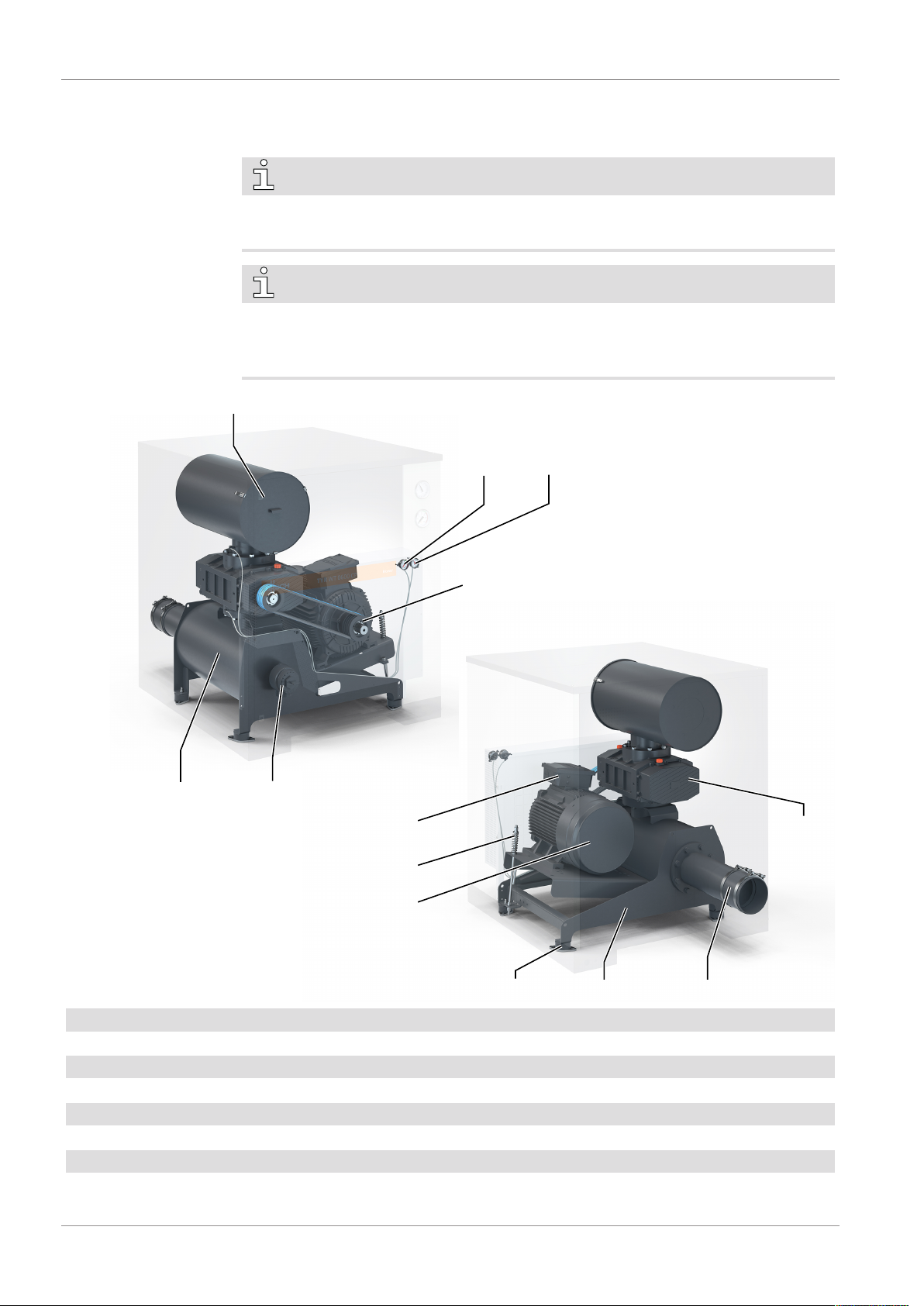
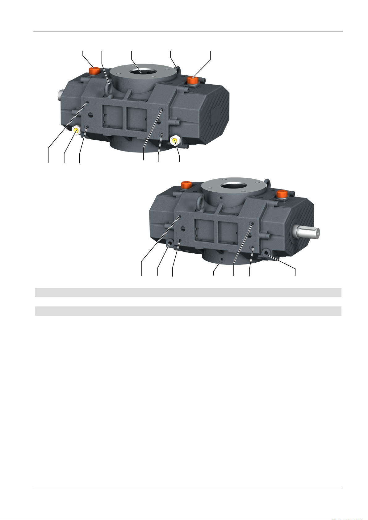
2 Product Description ..................................................................................................................4
2.1 Operating Principle .......................................................................................................... 6
2.2 Application....................................................................................................................... 6
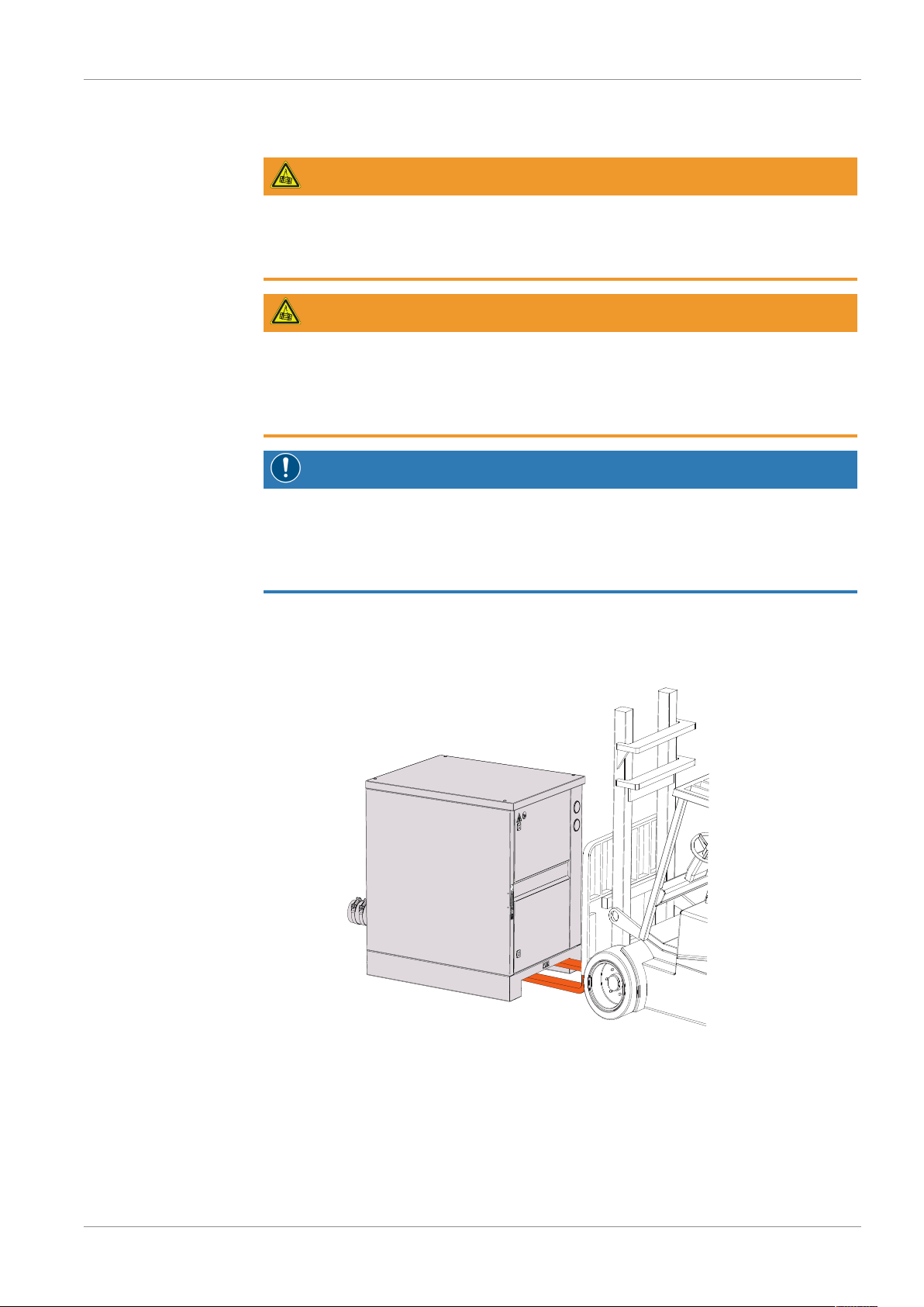
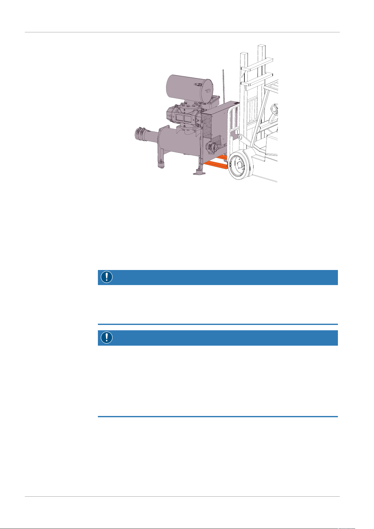
3 Transport ..................................................................................................................................7
4 Storage .....................................................................................................................................8
5 Installation................................................................................................................................9
5.1 Installation Conditions...................................................................................................... 9
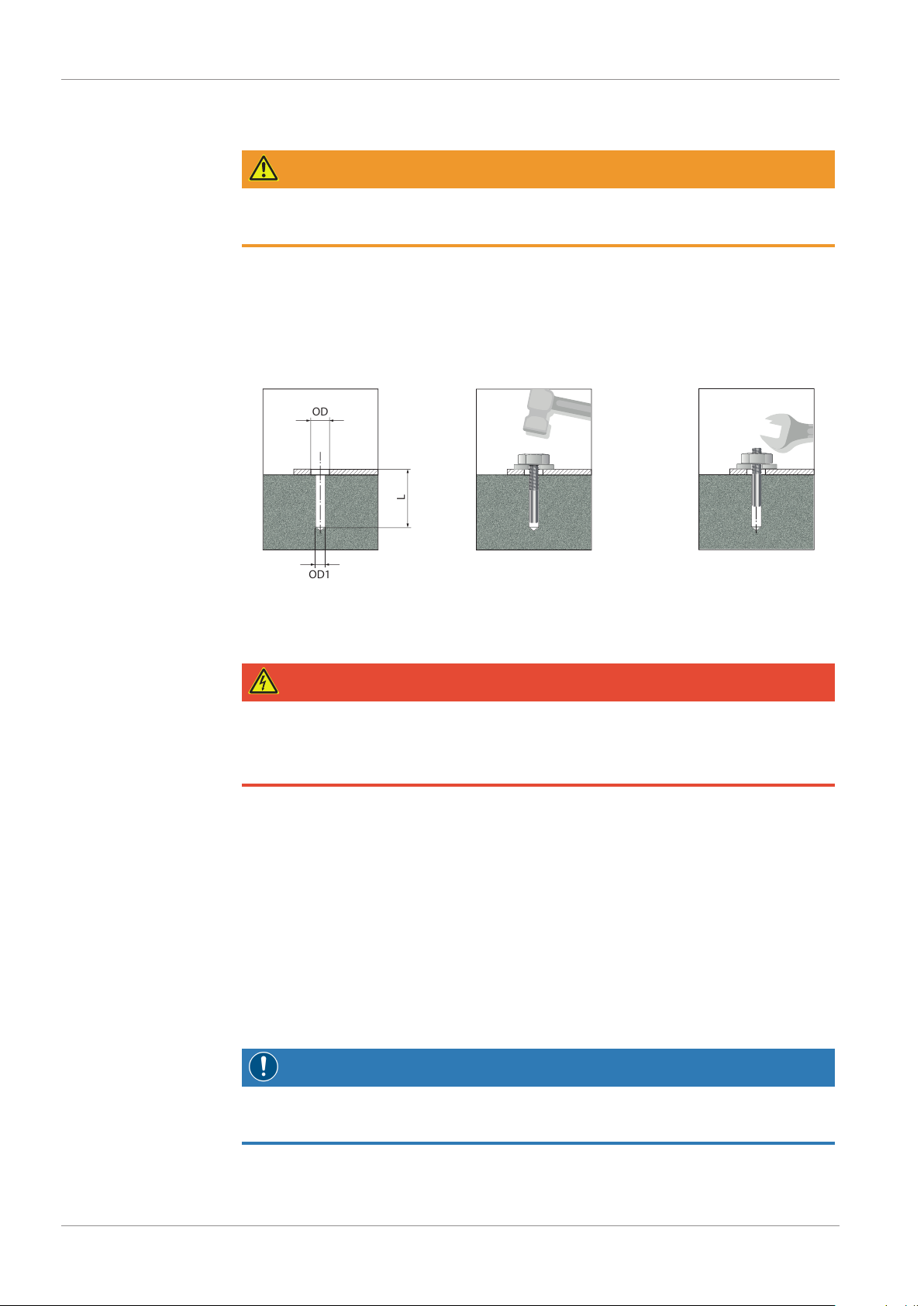
5.2 Blower Unit Installation .................................................................................................... 9
5.2.1 Possible fixing........................................................................................................ 10
5.3 Electrical Connection ........................................................................................................ 10
5.3.1 Wiring Diagram Three-Phase Motor...................................................................... 11
5.4 Connecting Lines / Pipes .................................................................................................. 12
5.4.1 Suction Connection ...............................................................................................12
5.4.2 Discharge Connection ........................................................................................... 13
5.5 Filling Oil.......................................................................................................................... 13
6 Commissioning.........................................................................................................................15
7 Maintenance.............................................................................................................................16
7.1 Maintenance Schedule ..................................................................................................... 17
7.2 Maintenance Inlet Filter.................................................................................................... 17
7.3 Maintenance V-Belt and Pulley Alignment ....................................................................... 19
7.4 Maintenance Oil .............................................................................................................. 20
7.5 Oil Level Inspection.......................................................................................................... 20
7.6 Oil Change....................................................................................................................... 21
8 Overhaul...................................................................................................................................24
9 Decommissioning.....................................................................................................................24
9.1 Dismantling and Disposal ................................................................................................. 24
10 Spare Parts................................................................................................................................25
11 Troubleshooting .......................................................................................................................26
12 Technical Data..........................................................................................................................31
13 Specific Technical Data.............................................................................................................32
14 Oil ............................................................................................................................................33
15 EU Declaration of Conformity...................................................................................................34
16 UK Declaration of Conformity ..................................................................................................35

Safety | 1
0870231979_WT0100-0730CP_CV_-0001_IM_en 3 / 36
1 Safety
Prior to handling the machine, this instruction manual should be read and understood. If
anything needs to be clarified, please contact your Busch representative.
Read this manual carefully before use and keep for future reference.
This instruction manual remains valid as long as the customer does not change anything
on the product.
The machine is intended for industrial use. It must be handled only by technically trained
personnel.
Always wear appropriate personal protective equipment in accordance with the local
regulations.
The machine has been designed and manufactured according to state-of-the-art meth-
ods. Nevertheless, residual risks may remain. This instruction manual highlights potential
hazards where appropriate. Safety notes and warning messages are tagged with one of
the keywords DANGER, WARNING, CAUTION, NOTICE and NOTE as follows:
DANGER
... indicates an imminent dangerous situation that will result in death or serious injuries if
not prevented.
WARNING
... indicates a potentially dangerous situation that could result in death or serious injuries.
CAUTION
... indicates a potentially dangerous situation that could result in minor injuries.
NOTICE
... indicates a potentially dangerous situation that could result in damage to property.
NOTE
... indicates helpful tips and recommendations, as well as information for efficient and
trouble-free operation.

2 | Product Description
4 / 36 0870231979_WT0100-0730CP_CV_-0001_IM_en
2 Product Description
NOTE
Illustrations
In this instruction manual the illustrations may differ from the machine appearance.
NOTE
Technical term.
In this instruction manual, we consider that the term ‘machine’ refers to the ‘rotary lobe
blower package for overpressure or vacuum operation’.
MOT
MTB
OUT, RN
IN, SI
BD
FMO
FRP SF
PG
BSB
OUT, SI PRE
PTS
BD Belt drive BSB Bare shaft blower
FMO Filter monitoring FRP Feet with rubber pads
IN Blower inlet MOT Motor
MTB Motor terminal box OUT Blower outlet
PG Pressure gauge PRE Pressure relief valve
PTS Pre-tensioning system SI Silencer
RN Rubber hose SF Supporting frame

Product Description | 2
0870231979_WT0100-0730CP_CV_-0001_IM_en 5 / 36
OUT
OFP OFP
IN
MP
OSG
MP
EB EB
OSG
CWC CWC CWC CWC
CWC CWC CWC CWC
EB Eyebolt IN Blower inlet
MP Magnetic plug OFP Oil fill plug
OSG Oil sight glass OUT Blower outlet
CWC Cooling water connection

2 | Product Description
6 / 36 0870231979_WT0100-0730CP_CV_-0001_IM_en
2.1 Operating Principle
The machine with tri-lobe rotors work on the principle of oil-free gas transport.
Two identical lobes rotate in opposite direction in the casing, transporting fixed volume
of air with each turn. There is no contact between the rotors and also between rotor and
casing, therefore process does not require oil in the working area. The machine trans-
ports the gas without increasing the pressure.
Gas is compressed in the machine outlet by the gas that has already transported (blowers
with external compression).
2.2 Application
The machine is intended for transport of air and other dry, non-aggressive, non-toxic
and non-explosive gases.
The machine is intended for the placement in a non-potentially explosive environment.
The machine is suitable for continuous as well as intermittent operation.
Permitted environmental conditions, see Technical Data [►31].
NOTICE
Chemical compatibility of the process gases with the machine component materials.
Risk of corrosion inside the blower working area which can reduce performance and its
lifetime!
• Check if the process gases are compatible with those following materials:
- Cast iron
- Steel
- Aluminium
- Fluoroelastomer (FKM/FPM)
• In doubt, please contact your Busch representative.

Transport | 3
0870231979_WT0100-0730CP_CV_-0001_IM_en 7 / 36
3 Transport
WARNING
Suspended load.
Risk of severe injury!
• Do not walk, stand or work under suspended loads.
WARNING
Lifting the machine using the motor eye bolt.
Risk of severe injury!
• Do not lift the machine using the eye bolt fitted to the motor. Only lift the machine as
shown.
NOTICE
In case the machine is already filled with oil.
Tilting a machine that is already filled with oil can cause large quantities of oil to in-
gress into the casing.
• Drain the oil prior to every transport or always horizontally transport the machine.
• Check the machine for transport damage.
If the machine is secured to a base plate:
• Remove the machine from the base plate.
With cabinet

4 | Storage
8 / 36 0870231979_WT0100-0730CP_CV_-0001_IM_en
Without cabinet
4 Storage
• Seal all apertures with adhesive tape or reuse provided caps.
If the machine is to be stored for more than 3 months:
• Wrap the machine in a corrosion inhibiting film.
• Store the machine indoors, dry, dust free and if possible in original packaging
preferably at temperatures between .
NOTICE
Long storage time (over 6 months).
The blower shaft should be rotated by hand periodically, at least once a month, in or-
der to renew the grease on the bearing races and keep a periodical record. Failure to
carry out this procedure could invalidate the product warranty.
NOTICE
Long storage time (more than 6 months).
For long storage time or storage in a warehouse with substantial fluctuations in tem-
perature and/or an aggressiv atmosphere, the rotary lobe blower must be prepared in a
special procedure from Busch Vyroba CZ s.r.o. (according to customer information dur-
ing order preparation).
All specific preparations and procedures must be preserved during a storaging all the
time. The rotary lobe blower must be wrapped in a special VCI foil all the time during
storaging.

Installation | 5
0870231979_WT0100-0730CP_CV_-0001_IM_en 9 / 36
5 Installation
5.1 Installation Conditions
NOTICE
Use of the machine outside of the permitted installation conditions.
Risk of premature failure!
Loss of efficiency!
• Take care that the installation conditions are fully complied with.
• Make sure that the environment of the machine is not potentially explosive.
• Make sure that the ambient conditions comply with the Technical Data [►31].
• Make sure that the environmental conditions comply with the protection class of the
motor and the electrical instruments.
• Make sure that the installation space or location is vented such that sufficient cooling
of the machine is provided.
• Make sure that cooling air inlets and outlets are not covered or obstructed and that
the cooling air flow is not affected adversely in any other way.
• Check the oil level, see Oil Level Inspection [►20].
• Make sure that all provided covers, guards, hoods, etc. are mounted.
Make sure that the machine is fixed to the concrete base with anchors, see Possible Fix-
ing below.
• Make sure that the machine is secured against movement.
5.2 Blower Unit Installation
The machine must be set up horizontally on a flat surface.
Maximum permissible unevenness of the base / inclination of the machine can be ex-
pressed as follows:
• View from left to right and the front to back : max. 0.5°
We recommend to keep 1 meter space around the machine for the maintenance work.
1 m
1 m
1 m
1 m
Make sure that the machine is fixed to the concrete base with anchors, see Possible Fix-
ing below.

5 | Installation
10 / 36 0870231979_WT0100-0730CP_CV_-0001_IM_en
5.2.1 Possible fixing
WARNING
After being set in its position, the machine must be anchored to the floor.
Otherwise, it could move spontaneously and thus be damaged.
Working procedure for anchoring machine and noise-damping hoods.
• Drill a hole and clean it (A)
• Stick the anchor into the hole (B); and
• Tighten the nut (C)
OD
OD1
L
A) B) C)
5.3 Electrical Connection
DANGER
Live wires.
Risk of electrical shock.
• Electrical installation work must only be executed by qualified personnel.
• Make sure that the power supply for the motor is compatible with the data on the
nameplate of the motor.
• The electrical installation must comply with applicable national and international
standards.
• Provide a lockable disconnect switch on the power line so that the machine is com-
pletely secured during maintenance tasks.
• Provide an overload protection according to EN 60204-1 for the motor.
• Make sure that the motor of the machine will not be affected by electric or electro-
magnetic disturbance from the mains; if necessary seek advice from Busch.
• Connect the protective earth conductor.
• Electrically connect the motor.
NOTICE
The motor frequency is below 20 Hz.
Risk of damage to the machine!

Installation | 5
0870231979_WT0100-0730CP_CV_-0001_IM_en 11 / 36
NOTICE
Incorrect connection.
Risk of damage to the motor!
• The wiring diagrams given below are typical. Check the inside of the terminal box for
motor connection instructions/diagrams.
5.3.1 Wiring Diagram Three-Phase Motor
NOTICE
Incorrect direction of rotation.
Risk of damage to the machine!
• Operation in the wrong direction of rotation can destroy the machine in a short time!
Prior to start-up, ensure that the machine is operated in the right direction.
The intended rotation direction of the motor is defined by the specific instruction label
stuck on the machine.
• Jog the motor briefly.
• Watch the fan wheel of the motor and determine the direction of rotation just before
the fan wheel stops.
If the rotation of the motor must be changed:
• Switch any two of the motor phase wires.
Delta connection (low voltage): Star connection (high voltage):
Double star connection, multi-voltage
motor with 9 pins (low voltage):
Star connection, multi-voltage motor
with 9 pins (high voltage):

5 | Installation
12 / 36 0870231979_WT0100-0730CP_CV_-0001_IM_en
Double star connection, multi-voltage
motor with 12 pins (low voltage):
4
4
4
Star connection, multi-voltage motor
with 12 pins (high voltage):
4
4
4
Delta connection, multi-voltage motor
with 12 pins (middle voltage):
4
4
4
5.4 Connecting Lines / Pipes
• Remove all protective covers before installation.
• Make sure that the connection lines cause no stress on the machine‘s connection; if
necessary use flexible joints.
• Make sure that the line size of the connection lines over the entire length is at least as
large as the connections of the machine.
In case of long connection lines it is advisable to use larger line sizes in order to avoid a
loss of efficiency. Seek advice from your Busch representative.
WARNING
The pipe installation must be made from conducting material in order to avoid build up
of static electricity.
Pipe installation on the exhaust side must be made from heat resistant material.
Risk of severe injury!
Risk of damage to the machine!
5.4.1 Suction Connection
WARNING
Unprotected suction connection.
Risk of severe injury!
• Do not put hand or fingers in the suction connection.

Installation | 5
0870231979_WT0100-0730CP_CV_-0001_IM_en 13 / 36
NOTICE
Ingress of foreign objects or liquids.
Risk of damage to the machine!
If the inlet gas contains dust or other foreign solid particles:
• Install a suitable filter (5micron or less) upstream from the machine.
Connection size(s):
– Ø 114 mm for WT 0100 CV/CP and WT 0150 CV/CP
– Ø 159 mm for WT 0280 CV/CP and WT 0390 CV/CP
– Ø 219 mm for WT 0600 CV/CP and WT 0730 CV/CP
Depending on the specific order, other connection dimensions may apply.
5.4.2 Discharge Connection
Connection size(s):
– Ø 114 mm for WT 0100 CV/CP and WT 0150 CV/CP
– Ø 159 mm for WT 0280 CV/CP and WT 0390 CV/CP
– Ø 219 mm for WT 0600 CV/CP and WT 0730 CV/CP
Depending on the specific order, other connection dimensions may apply.
• Make sure that the discharged gas will flow without obstruction.
5.5 Filling Oil
NOTICE
Use of an inappropriate oil.
Risk of premature failure!
Loss of efficiency!
• Only use an oil type which has previously been approved and recommended by
Busch.
For oil type and oil capacity see Technical Data [►31] and Oil [►33].
When the oil filling is achieved:
• Write down the oil change date on the sticker.
Last oil change
__ / __ / ____
Oil type see nameplate
Change interval see
instruction manual
If there is no sticker (part no. 0565 568 959) on the machine:
• Order it from your Busch representative.

5 | Installation
14 / 36 0870231979_WT0100-0730CP_CV_-0001_IM_en
1
Busch Oil
2
3
MIN
4
Check oil level
Oil filling at the shaft side
1
Busch Oil
2
3
MIN
4
Check oil level
Oil filling at the gear side

Commissioning | 6
0870231979_WT0100-0730CP_CV_-0001_IM_en 15 / 36
6 Commissioning
CAUTION
During operation the surface of the machine may reach temperatures of more than
70°C.
Risk of burns!
• Avoid contact with the machine during and directly after operation.
CAUTION
Noise of running machine.
Risk of damage to hearing!
If persons are present in the vicinity of a non noise insulated machine over extended
periods:
• Make sure that ear protection is being used.
• Make sure that the installation conditions (see Installation Conditions [►9]) are met.
• Switch on the machine.
• Make sure that the maximum permissible number of starts does not exceed the fol-
lowing recommendations :
From 3 kW to 11 kW 12 starts per hour
From 15 kW to 90 kW 6 starts per hour
• Make sure that the operating conditions comply with the Technical Data [►31].
• After a few minutes of operation, perform an Oil Level Inspection [►20].
As soon as the machine is operated under normal operating conditions:
• Measure the motor current and record it as reference for future maintenance and
troubleshooting work.
NOTICE
The machine can be shipped without oil.
Operation without oil will ruin the machine in short time!
• Prior to commissioning, the machine must be filled with oil, see Filling Oil [►13].
NOTICE
Lubricating a dry running machine (compression chamber).
Risk of damage to the machine!
• Do not lubricate the compression chamber of the machine with oil or grease.

7 | Maintenance
16 / 36 0870231979_WT0100-0730CP_CV_-0001_IM_en
7 Maintenance
WARNING
Machines contaminated with hazardous material.
Risk of poisoning!
Risk of infection!
If the machine is contaminated with hazardous material:
• Wear appropriate personal protective equipment.
CAUTION
Hot surface.
Risk of burns!
• Prior to any action requiring touching the machine, let the machine cool down first.
NOTICE
Using inappropriate cleaners.
Risk of removing safety stickers and protective paint!
• Do not use incompatible solvents to clean the machine.
CAUTION
Failing to properly maintain the machine.
Risk of injuries!
Risk of premature failure and loss of efficiency!
• Respect the maintenance intervals or ask your Busch representative for service.
• Shut down the machine and lock against inadvertent start up.
• Vent the connected lines to atmospheric pressure.
If necessary:
• Disconnect all connections.

Maintenance | 7
0870231979_WT0100-0730CP_CV_-0001_IM_en 17 / 36
7.1 Maintenance Schedule
The maintenance intervals depend very much on the individual operating conditions. The
intervals given below are considered as starting values which should be shortened or ex-
tended as appropriate. Particularly harsh applications or heavy duty operation, such as
high dust loads in the environment or in the process gas, other contamination or ingress
of process material, can make it necessary to shorten the maintenance intervals signifi-
cantly.
NOTE
The machine must be turned off at the service breaker and secured against wrongful re-
activation during all service work.
Interval Maintenance work
Every 6 months • Carry out a visual inspection and clean the machine
from dust and dirt.
• Check the electrical connections and the monitoring
devices.
Every 32000 hours • Recommend planning a preventive overhaul for every
32000 hours operation.
According to the motor
manual
• Check the motor. Lubricate the motor if necessary.
(In accordance with the motor manual).
7.2 Maintenance Inlet Filter
The inlet filter must be cleaned regularly or more often depending on application. The
frequency depends on the application, but the filter must be cleaned at least once every
six months.
The filter must not be washed.
The filter’s dirt level is monitored by the supplied filter gauge that is built into the v-belt
cover or the cabinet front.
Cleaning with compressed air does not ensure a 100% clean wrap filter, it is therefore
recommended to replace it with a new one.
Interval Maintenance work
After 10-20 operating hours • Check the inlet filter and clean if necessary. (See
clean or change inlet filter, point 5)
Monthly (or more often de-
pending on application).
• Check the inlet filter and clean if necessary. (See
clean or change inlet filter, point 5)
Half - yearly • Change the inlet filter (or more often depending on
application). (See clean or change inlet filter, point 5)
Yearly • Change the inlet filter (or more often depending on
application). (See clean or change inlet filter, point 5)

7 | Maintenance
18 / 36 0870231979_WT0100-0730CP_CV_-0001_IM_en
31
2
12
1
2
3
3x
1
2
3
4
5
6
7
or
Close the cover after that
Clean or Change the Inlet Filter

Maintenance | 7
0870231979_WT0100-0730CP_CV_-0001_IM_en 19 / 36
7.3 Maintenance V-Belt and Pulley Alignment
Interval Maintenance work
After 10-20 operating hours • Check the belt tension and the V-belts.
• Check the pulley alignments
Half – yearly (or more often
depending on application).
• Check the belt tension and the V-belts.
• Check the pulley alignments
Once a year • Change the V-belts.
• V-belt change intervals for higher loads and ambient
temperatures (more than +40°C) range from 4000 to
max. 8000 hours.
1. Parallel offset:
Product Permissible parallel
offset of two pulleys
10 mm per
1000 mm of strand lenght
V-belts & multiple
V-ribbed belts
max. 1% of center distance for V-belts
2. Angular offset of two pulleys:
Product Permissible angular
offset of two pulleys
0.5°
V-belts & multiple
V-ribbed belts
max. 0.5° for V-belts
3. Axial twist of pulleys:
Product Permissible axial twist
of pulleys
0.25°
V-belts & multiple
V-ribbed belts
max. 0.25° for V-belts

7 | Maintenance
20 / 36 0870231979_WT0100-0730CP_CV_-0001_IM_en
7.4 Maintenance Oil
Bearing temperature
[°C]
See Specific Tech-
nical Data [►32]
Interval Maintenance work
After 10-20 operating
hours
• Check the oil level,
see Oil Level Inspection [►20].
Weekly • Check the oil level,
see Oil Level Inspection [►20].
After 500 operating
hours
• Change for newly operated blower.
≤110 Every 8000 hours • Change the oil (min. once a year).
111-130 Every 4000 hours • Change the oil (min. every 6 months).
7.5 Oil Level Inspection
• Shut down the machine.
• When the machine is stopped, wait 1 minute before checking the oil level.
With cabinet
MIN
• Fill up if necessary, see Oil Filling [►13].
Table of contents
Other BUSCH Blower manuals