BUSCH PANDA WV 1200 A User manual

Get technical data,
instruction manuals,
service kits
Instruction Manual
PANDA
Vacuum Booster
WV 1200 A, WV 1800 A, WV 2400 A
0870572562/A0005_en / Original instructions / Modifications reserved 15/06/2021

Table of Contents
2 / 28 0870572562_WV1200-2400A_A0005_IM_en
Table of Contents
1 Safety .......................................................................................................................................3
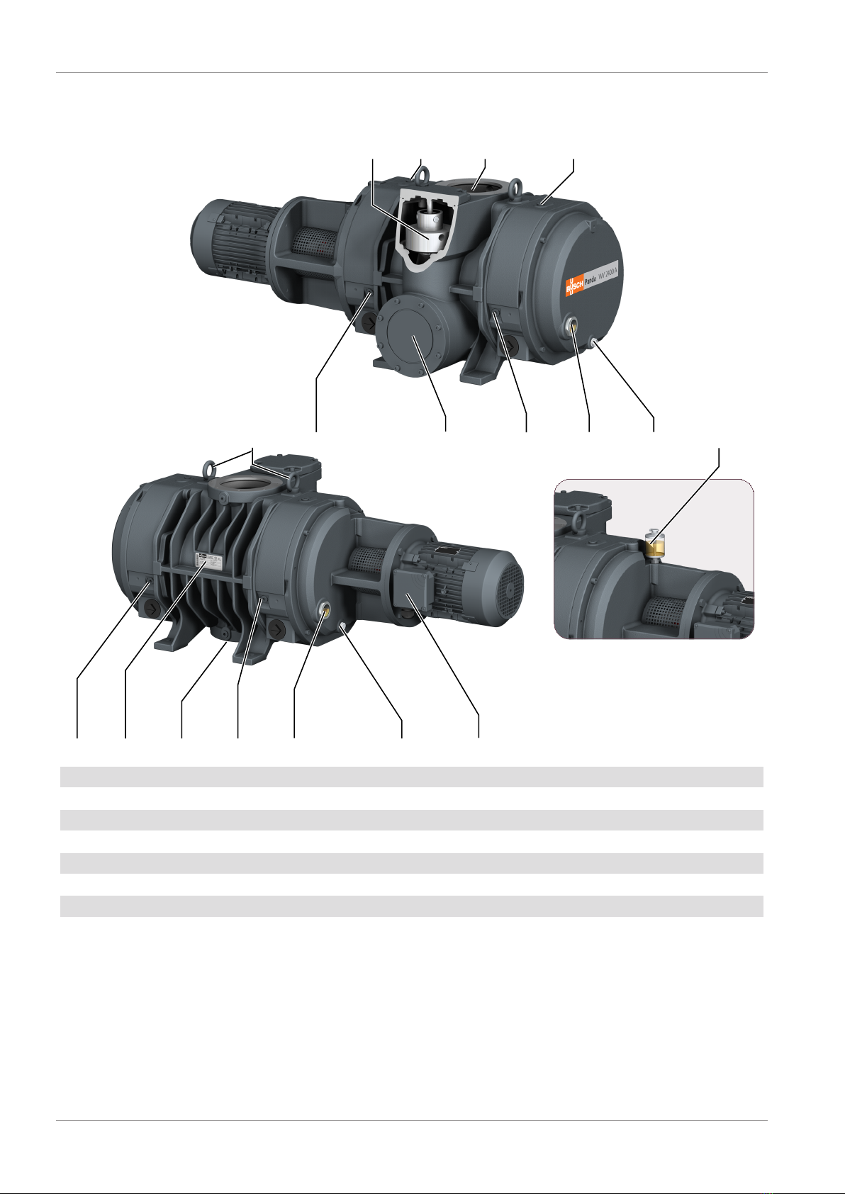
2 Product Description ..................................................................................................................4
2.1 Operating Principle .......................................................................................................... 5
2.2 Application....................................................................................................................... 5
2.3 Shaft Sealing Variants....................................................................................................... 6
2.3.1 Mechanical Seal..................................................................................................... 6
2.3.2 Lip Seals (Optional) ............................................................................................... 6
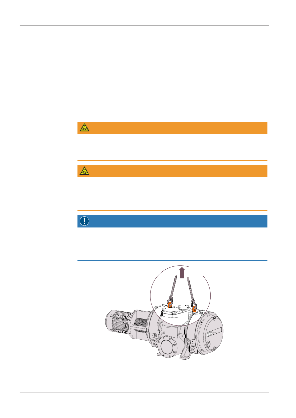
3 Transport ..................................................................................................................................6
4 Storage .....................................................................................................................................7
5 Installation................................................................................................................................7
5.1 Installation Conditions...................................................................................................... 7
5.2 Connecting Lines / Pipes .................................................................................................. 8
5.2.1 Gas Flow Variants.................................................................................................. 8
5.2.2 Suction Connection ............................................................................................... 8
5.2.3 Discharge Connection ........................................................................................... 9
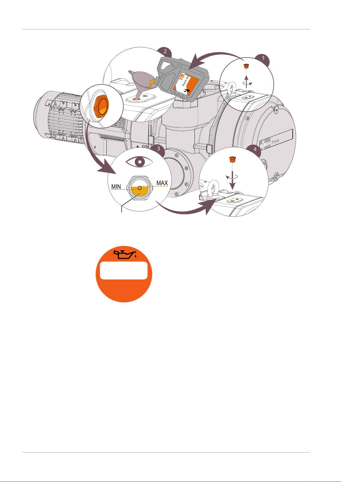
5.3 Filling Oil.......................................................................................................................... 9
5.4 Fitting the Coupling ......................................................................................................... 11
5.5 Electrical Connection ........................................................................................................ 11
5.5.1 Wiring Diagram Three-Phase Motor...................................................................... 12
6 Commissioning.........................................................................................................................13
6.1 Compression Chamber Flushing ....................................................................................... 14
7 Maintenance.............................................................................................................................15
7.1 Maintenance Schedule ..................................................................................................... 16
7.2 Oil Level Inspection.......................................................................................................... 16
7.3 Oil Colour Inspection ....................................................................................................... 16
7.4 Oil Change....................................................................................................................... 17
8 Overhaul...................................................................................................................................20
9 Decommissioning.....................................................................................................................20
9.1 Dismantling and Disposal ................................................................................................. 20
10 Spare Parts................................................................................................................................21
11 Troubleshooting .......................................................................................................................21
12 Technical Data..........................................................................................................................23
13 Maximum Permissible Differential Pressures............................................................................24
14 Oil ............................................................................................................................................25
15 EU Declaration of Conformity...................................................................................................26
16 UK Declaration of Conformity ..................................................................................................27

Safety | 1
0870572562_WV1200-2400A_A0005_IM_en 3 / 28
1 Safety
Prior to handling the machine, this instruction manual should be read and understood. If
anything needs to be clarified, please contact your Busch representative.
Read this manual carefully before use and keep for future reference.
This instruction manual remains valid as long as the customer does not change anything
on the product.
The machine is intended for industrial use. It must be handled only by technically trained
personnel.
Always wear appropriate personal protective equipment in accordance with the local
regulations.
The machine has been designed and manufactured according to state-of-the-art meth-
ods. Nevertheless, residual risks may remain. This instruction manual highlights potential
hazards where appropriate. Safety notes and warning messages are tagged with one of
the keywords DANGER, WARNING, CAUTION, NOTICE and NOTE as follows:
DANGER
... indicates an imminent dangerous situation that will result in death or serious injuries if
not prevented.
WARNING
... indicates a potentially dangerous situation that could result in death or serious injuries.
CAUTION
... indicates a potentially dangerous situation that could result in minor injuries.
NOTICE
... indicates a potentially dangerous situation that could result in damage to property.
NOTE
... indicates helpful tips and recommendations, as well as information for efficient and
trouble-free operation.

2 | Product Description
4 / 28 0870572562_WV1200-2400A_A0005_IM_en
2 Product Description
OFPBPV IN
OSG ODP, MP
OFP
ODP, MP MTBOSGOUT1
BGC
BGCBGC
OR
OUT2BGC
NP
EB
WV 2400 A
WV 2400 A WV 2400 A with lip seals variant
(Optional)
BGC Barrier gas connection BPV Bypass valve
EB Eye bolt IN Suction connection
MP Magnetic plug MTB Motor terminal box
NP Nameplate ODP Oil drain plug
OFP Oil fill plug OR Oiler (Optional)
OSG Oil sight glass OUT Discharge connection
OUT2 Lateral discharge connection (Optional)

Product Description | 2
0870572562_WV1200-2400A_A0005_IM_en 5 / 28
NOTE
Technical term.
In this instruction manual, we consider that the term ‘machine’ refers to the ‘vacuum
booster’.
NOTE
Illustrations
In this instruction manual the illustrations may differ from the machine appearance.
2.1 Operating Principle
The machine works on the Roots blower principle.
The two oil housings (on each side) allow the lubrication of the gears, bearings and in
certain versions the oil lubricated mechanical seals.
A bypass valve (BPV) limits automatically the differential pressure between inlet and outlet.
2.2 Application
The machine is intended for the suction of air and other dry, non-aggressive, non-toxic
and non-explosive gases.
Conveying of other media leads to an increased thermal and/or mechanical load on the
machine and is permissible only after a consultation with Busch.
The machine is intended for the placement in a non-potentially explosive environment.
The vacuum booster is used in combination with a backing pump in vacuum system.
The machine is suitable for continuous operation.
Permitted environmental conditions, see Technical Data [►23].
NOTICE
Chemical compatibility of the process gases with the machine component materials.
Risk of corrosion inside the compression chamber which can reduce performance and
its lifetime!
• Check if the process gases are compatible with those following materials:
- Cast iron
- Steel
- Aluminium
- Fluoroelastomer (FKM/FPM)
• In doubt, please contact your Busch representative.

3 | Transport
6 / 28 0870572562_WV1200-2400A_A0005_IM_en
2.3 Shaft Sealing Variants
2.3.1 Mechanical Seal
The shaft sealing consists, in standard execution, of a mechanical seal.
2.3.2 Lip Seals (Optional)
Optionally, the shaft sealing may consist of three lip seals. This variant requires an oiler
(OR) in order to continuously lubricate the sealing system.
3 Transport
WARNING
Suspended load.
Risk of severe injury!
• Do not walk, stand or work under suspended loads.
WARNING
Lifting the machine using the motor eye bolt.
Risk of severe injury!
• Do not lift the machine using the eye bolt fitted to the motor. Only lift the machine as
shown.
NOTICE
In case the machine is already filled with oil.
Tilting a machine that is already filled with oil can cause large quantities of oil to in-
gress into the cylinder.
• Drain the oil prior to every transport or always horizontally transport the machine.
Machine weight:
see the technical data or the nameplate (NP)
• Check the machine for transport damage.
If the machine is secured to a base plate:
• Remove the machine from the base plate.

Storage | 4
0870572562_WV1200-2400A_A0005_IM_en 7 / 28
4 Storage
• Seal all apertures with adhesive tape or reuse provided caps.
If the machine is to be stored for more than 3 months:
• Wrap the machine in a corrosion inhibiting film.
• Store the machine indoors, dry, dust free and if possible in original packaging
preferably at temperatures between -20 ... 55 °C.
5 Installation
5.1 Installation Conditions
NOTICE
Use of the machine outside of the permitted installation conditions.
Risk of premature failure!
Loss of efficiency!
• Take care that the installation conditions are fully complied with.
• Make sure that the environment of the machine is not potentially explosive.
• Make sure that the ambient conditions comply with the Technical Data [►23].
• Make sure to use a suitable backing pump, if necessary seek advice from your Busch
representative
• Make sure that the environmental conditions comply with the protection class of the
motor and the electrical instruments.
• Make sure that the installation space or location is vented such that sufficient cooling
of the machine is provided.
• Make sure that cooling air inlets and outlets are not covered or obstructed and that
the cooling air flow is not affected adversely in any other way.
• Make sure that the oil sight glass (OSG) remains easily visible.
• Make sure that enough space remains for maintenance work.
• Make sure that the machine is placed or mounted horizontally, a maximum of 1° in
any direction is acceptable.
• Make sure that the machine is secured either from the four feet or from the discharge
flange.
• Check the oil level, see Oil Level Inspection [►16].
• Make sure that all provided covers, guards, hoods, etc. are mounted.
If the machine is installed at an altitude greater than 1000 meters above sea level:
• Contact your Busch representative, the motor should be derated or the ambient
temperature limited.

5 | Installation
8 / 28 0870572562_WV1200-2400A_A0005_IM_en
5.2 Connecting Lines / Pipes
• Remove all protective covers before installation.
• Make sure that the connection lines cause no stress on the machine‘s connection; if
necessary use flexible joints.
• Make sure that the line size of the connection lines over the entire length is at least as
large as the connections of the machine.
In case of long connection lines it is advisable to use larger line sizes in order to avoid a
loss of efficiency. Seek advice from your Busch representative.
5.2.1 Gas Flow Variants
The machine can be installed in different ways:
Lateral discharge (Optional)Vertical gas flow
(In some specific cases, other gas flow variantes may apply)
5.2.2 Suction Connection
WARNING
Unprotected suction connection.
Risk of severe injury!
• Do not put hand or fingers in the suction connection.
NOTICE
Ingress of foreign objects or liquids.
Risk of damage to the machine!
If the inlet gas contains dust or other foreign solid particles:
• Install a suitable filter (5micron or less) upstream from the machine.
Connection size(s):
– DN160, DIN 28404
Depending on the specific order, other connection dimensions may apply.

Installation | 5
0870572562_WV1200-2400A_A0005_IM_en 9 / 28
5.2.3 Discharge Connection
Connection size(s):
– DN100, DIN 28404 for WV 1200/1800 A
– DN160, DIN 28404 for WV 2400 A
Same connection size for lateral discharge (OUT2)
Depending on the specific order, other connection dimensions may apply.
• Make sure that the discharged gas will flow without obstruction. Do not shut off or
throttle the discharge line or use it as a pressurised air source.
5.3 Filling Oil
NOTICE
Use of an inappropriate oil.
Risk of premature failure!
Loss of efficiency!
• Only use an oil type which has previously been approved and recommended by
Busch.
For oil type and oil capacity see Technical Data [►23] and Oil [►25].
1
5
3
MAX
MIN
2
Busch Oil
Busch Oil
4
Check oil level
Fill up until the oiler (OR)
is at least two thirds full
Oil filling at the motor side
With lip seals variant only
(Optional)
With lip seals variant only
(Optional)

5 | Installation
10 / 28 0870572562_WV1200-2400A_A0005_IM_en
1
4
3
MAX
MIN
2
Busch Oil
Check oil level
Oil filling at the gear side
When the oil filling is achieved:
• Write down the oil change date on the sticker.
Last oil change
__ / __ / ____
Oil type see nameplate
Change interval see
instruction manual
If there is no sticker (part no. 0565 568 959) on the machine:
• Order it from your Busch representative.

Installation | 5
0870572562_WV1200-2400A_A0005_IM_en 11 / 28
5.4 Fitting the Coupling
E
Coupling hub (machine side) Coupling hub (motor side)Coupling spider
Radial screw
Max. admissible
torque: 10 Nm
Machine type Coupling size Value “E” (mm)
WV 1200 A ROTEX® 24 18
WV 1800 A
WV 2400 A ROTEX® 38 24
In case of a machine delivery without motor:
• Fit the second coupling hub on the motor shaft (separately delivered).
• Axially adjust the hub in such a way until value "E" is reached.
• When the coupling adjustment is done, lock the coupling hub by tightening the
radial screw.
• Mount the motor on the machine by including the coupling spider.
For further coupling information, go to www.ktr.com and download the instruction
manual of the ROTEX® coupling.
5.5 Electrical Connection
DANGER
Live wires.
Risk of electrical shock.
• Electrical installation work must only be executed by qualified personnel.
• Make sure that the power supply for the motor is compatible with the data on the
nameplate of the motor.
• The electrical installation must comply with applicable national and international
standards.
• Provide a lockable disconnect switch on the power line so that the machine is com-
pletely secured during maintenance tasks.
• Provide an overload protection according to EN 60204-1 for the motor.
• Make sure that the motor of the machine will not be affected by electric or electro-
magnetic disturbance from the mains; if necessary seek advice from Busch.
• Connect the protective earth conductor.
• Electrically connect the motor.

5 | Installation
12 / 28 0870572562_WV1200-2400A_A0005_IM_en
NOTICE
Incorrect connection.
Risk of damage to the motor!
• The wiring diagrams given below are typical. Check the inside of the terminal box for
motor connection instructions/diagrams.
5.5.1 Wiring Diagram Three-Phase Motor
NOTICE
Incorrect direction of rotation.
Risk of damage to the machine!
• Operation in the wrong direction of rotation can destroy the machine in a short time!
Prior to start-up, ensure that the machine is operated in the right direction.
The intended rotation direction of the motor is defined by the specific instruction label
stuck on the machine.
• Jog the motor briefly.
• Watch the fan wheel of the motor and determine the direction of rotation just before
the fan wheel stops.
If the rotation of the motor must be changed:
• Switch any two of the motor phase wires.
Delta connection (low voltage): Star connection (high voltage):
Double star connection, multi-voltage
motor with 9 pins (low voltage):
Star connection, multi-voltage motor
with 9 pins (high voltage):

Commissioning | 6
0870572562_WV1200-2400A_A0005_IM_en 13 / 28
Double star connection, multi-voltage
motor with 12 pins (low voltage):
4
4
4
Star connection, multi-voltage motor
with 12 pins (high voltage):
4
4
4
Delta connection, multi-voltage motor
with 12 pins (middle voltage):
4
4
4
6 Commissioning
CAUTION
During operation the surface of the machine may reach temperatures of more than 70°C.
Risk of burns!
• Avoid contact with the machine during and directly after operation.
CAUTION
Noise of running machine.
Risk of damage to hearing!
If persons are present in the vicinity of a non noise insulated machine over extended
periods:
• Make sure that ear protection is being used.
NOTICE
The machine can be shipped without oil.
Operation without oil will ruin the machine in short time!
• Prior to commissioning, the machine must be filled with oil, see Filling Oil [►9].
NOTICE
Lubricating a dry running machine (compression chamber).
Risk of damage to the machine!
• Do not lubricate the compression chamber of the machine with oil or grease.

6 | Commissioning
14 / 28 0870572562_WV1200-2400A_A0005_IM_en
• Make sure that the installation conditions (see Installation Conditions [►7]) are met.
• Switch on the machine.
• Make sure that the maximum permissible number of starts does not exceed 6 starts
per hour. Those starts should be spread within the hour.
• Make sure that the operating conditions comply with the Technical Data [►23].
• After a few minutes of operation, perform an Oil Level Inspection [►16].
As soon as the machine is operated under normal operating conditions:
• Measure the motor current and record it as reference for future maintenance and
troubleshooting work.
6.1 Compression Chamber Flushing
Depending on the process type (very demanding application), flushing through the com-
pression chamber (cylinder + lobes) might need to be performed. Seek advice from your
Busch representative.
NOTICE
Flushing without barrier gas.
Risk of damage to the machine!
• The flushing process can pass over into the bearings and the oil chambers!
Do not perform flushing without using the barrier gas.
Beforehand, a barrier gas must be connected according to the following illustration and
recommendations:
Process flow outlet (OUT)
2x Barrier gas
connection (BGC)
2x Barrier gas
connection (BGC)
Process flow inlet (IN)
Connection size:
– 4 x G3/8 (BGC)
Barrier gas requirements:
Gas type Dry nitrogen, air or other suitable gas
Gas temperature °C 0 ... 60
Filtration µm ≤ 5
Gas pressure bar ≥ Pressure of flushing fluid + 1 bar
Recommended flow rate SLM* 30
* standard litre per minute
• Stop the machine.
• Open the gas supply.
• Flush the machine.

Maintenance | 7
0870572562_WV1200-2400A_A0005_IM_en 15 / 28
When the flushing is finished:
• Close the gas supply.
• Dry the machine of flushing fluid.
Do not operate the machine in normal operating conditions with the barrier gas opened.
It might affect the ultimate pressure and the suction capacity.
7 Maintenance
WARNING
Machines contaminated with hazardous material.
Risk of poisoning!
Risk of infection!
If the machine is contaminated with hazardous material:
• Wear appropriate personal protective equipment.
CAUTION
Hot surface.
Risk of burns!
• Prior to any action requiring touching the machine, let the machine cool down first.
NOTICE
Using inappropriate cleaners.
Risk of removing safety stickers and protective paint!
• Do not use incompatible solvents to clean the machine.
CAUTION
Failing to properly maintain the machine.
Risk of injuries!
Risk of premature failure and loss of efficiency!
• Respect the maintenance intervals or ask your Busch representative for service.
• Shut down the machine and lock against inadvertent start up.
• Vent the connected lines to atmospheric pressure.
If necessary:
• Disconnect all connections.

7 | Maintenance
16 / 28 0870572562_WV1200-2400A_A0005_IM_en
7.1 Maintenance Schedule
The maintenance intervals depend very much on the individual operating conditions. The
intervals given below are considered as starting values which should be shortened or exten-
ded as appropriate. Particularly harsh applications or heavy duty operation, such as high
dust loads in the environment or in the process gas, other contamination or ingress of pro-
cess material, can make it necessary to shorten the maintenance intervals significantly.
Interval Maintenance work
Monthly • Check the oil level, see Oil Level Inspection [►16].
• Check the machine for oil leaks - in case of leaks have
the machine repaired (contact Busch).
After the first 500 hours • Change the oil of the gear and bearing housings
(both sides), see Oil Change [►17].
Every 6 months • Perform an oil inspection; change it if the oil has
changed its initial colour, see Oil Colour Inspection
[►16].
Every 5000 hours, at the latest
after 1 year
• Change the oil of the gear and bearing housings
(both sides)
• Clean the magnetic plugs (MP)
Yearly • Carry out a visual inspection and clean the machine
from dust and dirt.
• Check the electrical connections and the monitoring
devices.
Every 16000 hours, at the least
after 4 years
• Have a major overhaul on the machine (contact
Busch).
7.2 Oil Level Inspection
• Shut down the machine.
• When the machine is stopped, wait 1 minute before checking the oil level.
MAX
MIN MAX
MIN MAX
MIN
• Fill up if necessary, see Oil Filling [►9].
7.3 Oil Colour Inspection
• Make sure that the oil is either light or transparent.
If the oil becomes dark or looks different from the initial colour:
• Change the oil immediately, see Oil Change [►17].
You can consult your Busch representative in order to find out why this colour change
has occurred.

Maintenance | 7
0870572562_WV1200-2400A_A0005_IM_en 17 / 28
7.4 Oil Change
NOTICE
Use of an inappropriate oil.
Risk of premature failure!
Loss of efficiency!
•
Only use an oil type which has previously been approved and recommended by Busch.
2
1
34
5
Drain pan
Cleaning cloth
Oil draining at the motor side

7 | Maintenance
18 / 28 0870572562_WV1200-2400A_A0005_IM_en
1
3
2
Drain pan
Cleaning cloth
Oil draining at the gear side
For oil type and oil capacity see Technical Data [►23] and Oil [►25].
1
5
3
MAX
MIN
2
Busch Oil
Busch Oil
4
Check oil level
Fill up until the oiler (OR)
is at least two thirds full
Oil filling at the motor side
With lip seals variant only
(Optional)
With lip seals variant only
(Optional)

Maintenance | 7
0870572562_WV1200-2400A_A0005_IM_en 19 / 28
1
4
3
MAX
MIN
2
Busch Oil
Check oil level
Oil filling at the gear side
When the oil filling is achieved:
• Write down the oil change date on the sticker.
Last oil change
__ / __ / ____
Oil type see nameplate
Change interval see
instruction manual
If there is no sticker (part no. 0565 568 959) on the machine:
• Order it from your Busch representative.

8 | Overhaul
20 / 28 0870572562_WV1200-2400A_A0005_IM_en
8 Overhaul
WARNING
Machines contaminated with hazardous material.
Risk of poisoning!
Risk of infection!
If the machine is contaminated with hazardous material:
• Wear appropriate personal protective equipment.
NOTICE
Improper assembly.
Risk of premature failure!
Loss of efficiency!
• It is highly recommended that any dismantling of the machine that goes beyond any-
thing that is described in this manual should be done through Busch.
In case of the machine having conveyed gas that was contaminated with foreign materi-
als which are dangerous to health:
• Decontaminate the machine as much as possible and state the contamination
status in a ‘Declaration of Contamination’.
Busch will only accept machines that come with a completely filled in and legally binding
signed ‘Declaration of Contamination’ (form downloadable from
www.buschvacuum.com).
9 Decommissioning
• Shut down the machine and lock against inadvertent start up.
• Vent the connected lines to atmospheric pressure.
• Disconnect all connections.
If the machine is going to be stored:
• See Storage [►7].
9.1 Dismantling and Disposal
• Drain the oil.
• Separate special waste from the machine.
• Dispose of special waste in compliance with applicable regulations.
• Dispose of the machine as scrap metal.
Other manuals for PANDA WV 1200 A
1
This manual suits for next models
2
Table of contents
Other BUSCH Extender manuals

BUSCH
BUSCH Panda WV 4500 B User manual

BUSCH
BUSCH Panda WV 4500 B User manual

BUSCH
BUSCH PANDA WZ 0250 B User manual

BUSCH
BUSCH PANDA WZ 3600 A User manual

BUSCH
BUSCH Panda WV 4500 B User manual

BUSCH
BUSCH PANDA WZ 1200 A User manual

BUSCH
BUSCH PANDA WZ 2400 A User manual

BUSCH
BUSCH Panda WV 4500 B User manual

BUSCH
BUSCH PUMA User manual