BUSCH PANDA WZ 2400 A User manual

Get technical data,
instruction manuals,
service kits
Instruction Manual
PANDA
Vacuum Booster
WZ 2400 A
0870203784/-0001_en / Original instructions / Modifications reserved 01/04/2021
Ateliers Busch S.A.
Zone industrielle, 2906 Chevenez
Switzerland

Table of Contents
2 / 28 0870203784_WZ2400A_-0001_IM_en
Table of Contents
1 Safety .......................................................................................................................................3
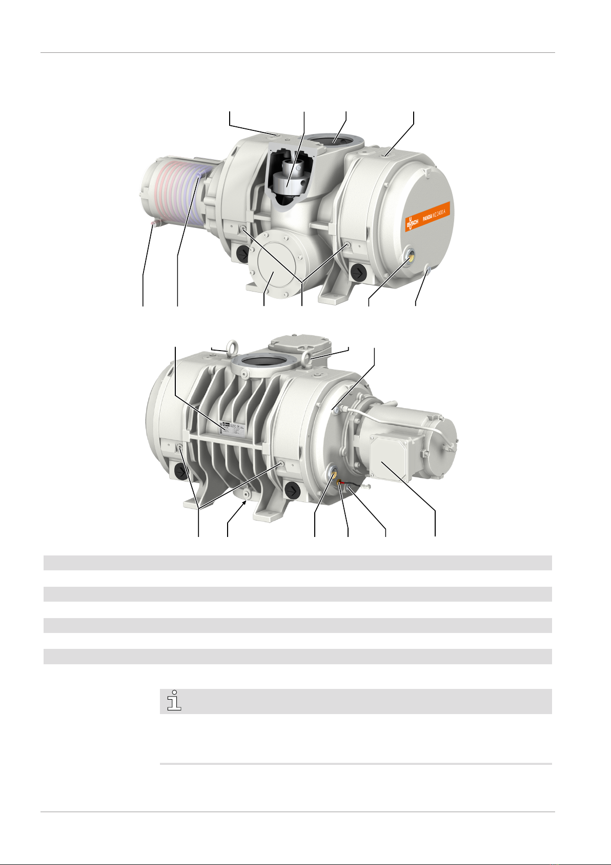
2 Product Description ..................................................................................................................4
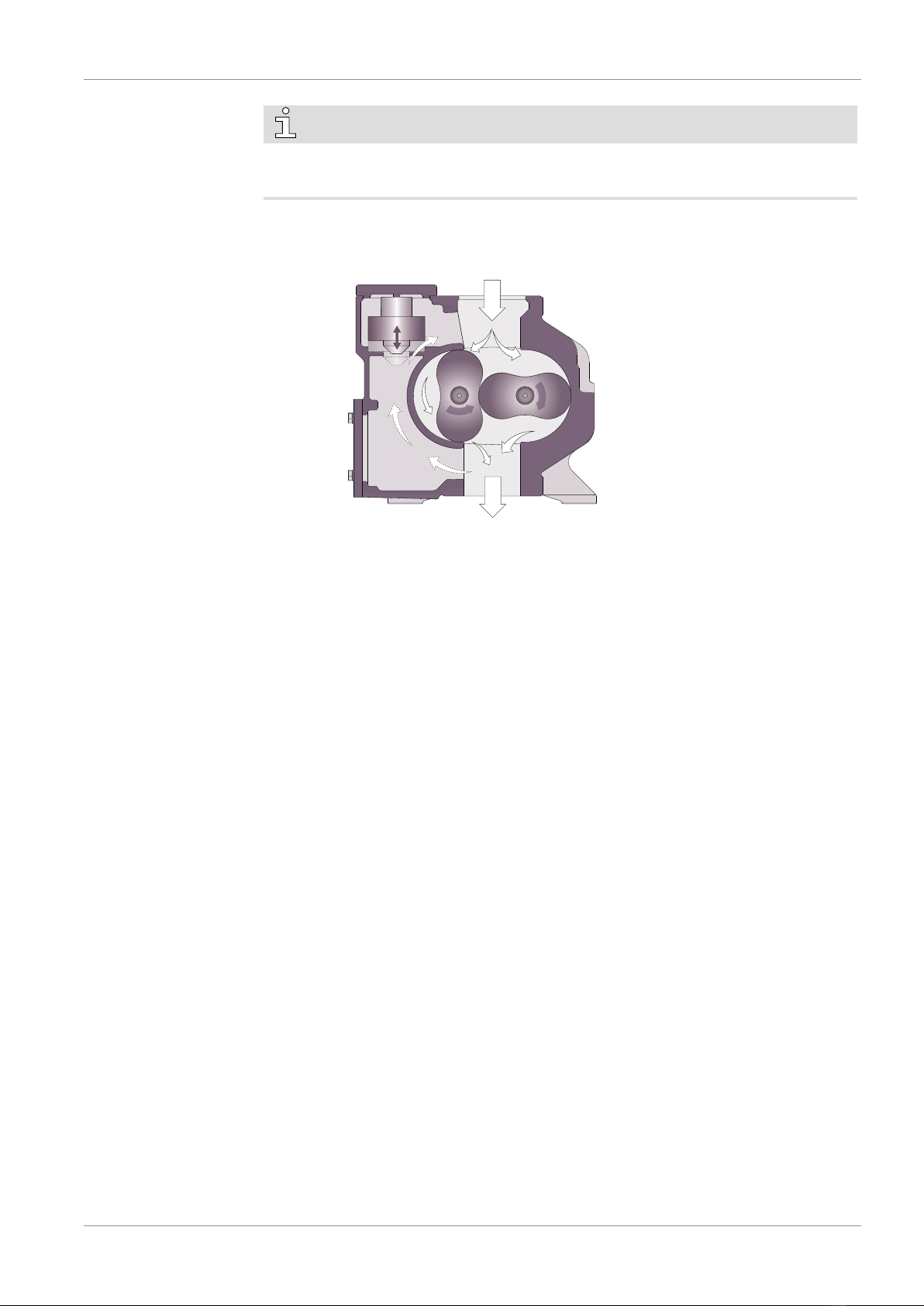
2.1 Operating Principle .......................................................................................................... 5
2.2 Application....................................................................................................................... 5
2.3 Standard Features ............................................................................................................ 6
2.3.1 Water Cooling.......................................................................................................6
2.3.2 Temperature Switch .............................................................................................. 6
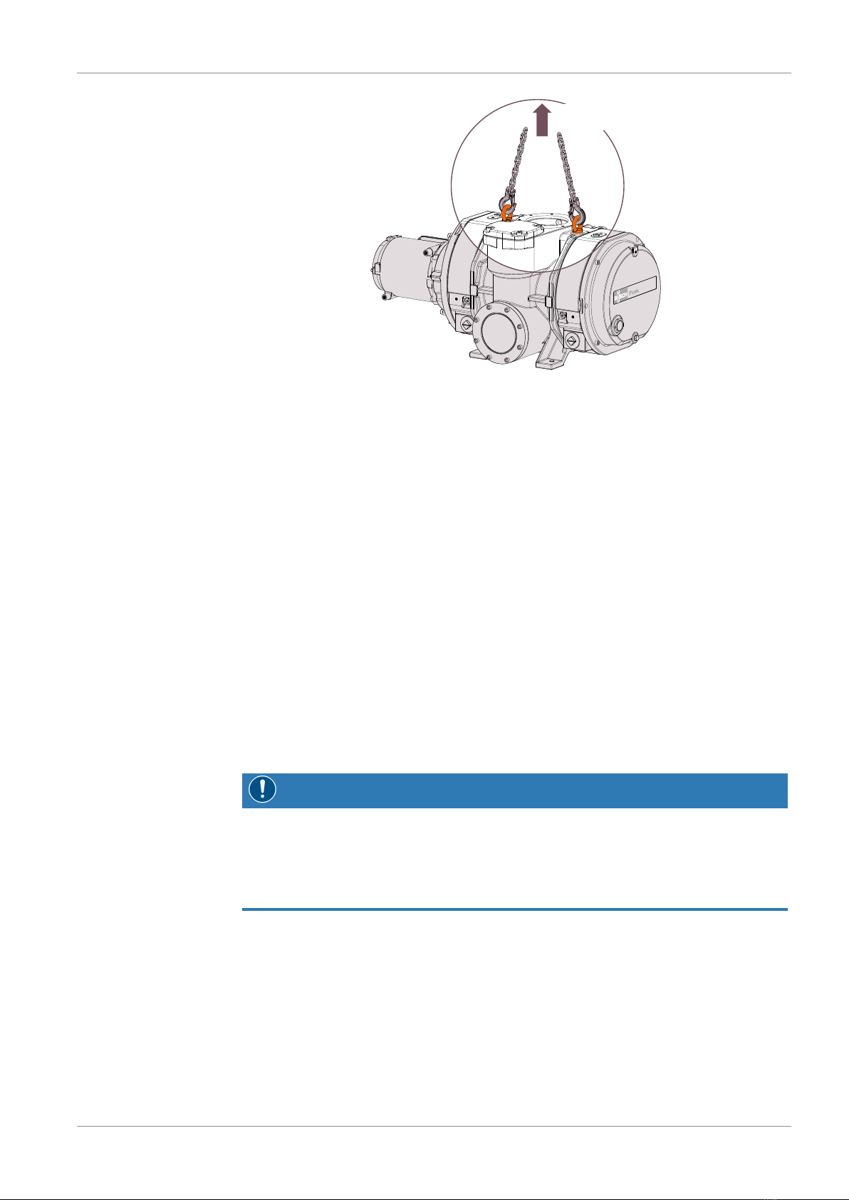
3 Transport ..................................................................................................................................6
4 Storage .....................................................................................................................................7
5 Installation................................................................................................................................7
5.1 Installation Conditions...................................................................................................... 7
5.2 Connecting Lines / Pipes .................................................................................................. 8
5.2.1 Gas Flow Variants.................................................................................................. 8
5.2.2 Suction Connection ............................................................................................... 9
5.2.3 Discharge Connection ........................................................................................... 9
5.2.4 Cooling Water Connection ....................................................................................9
5.3 Filling Oil.......................................................................................................................... 10
5.4 Electrical Connection ........................................................................................................ 12
5.4.1 Wiring Diagram Three-Phase Motor...................................................................... 13
5.5 Electrical Connection of the Monitoring Devices............................................................... 14
5.5.1 Wiring Diagram Temperature Switch..................................................................... 14
6 Commissioning.........................................................................................................................14
6.1 Compression Chamber Flushing ....................................................................................... 15
7 Maintenance.............................................................................................................................16
7.1 Maintenance Schedule ..................................................................................................... 17
7.1.1 With "YLC 250 B" Oil...........................................................................................17
7.2 Oil Level Inspection.......................................................................................................... 17
7.3 Oil Colour Inspection ....................................................................................................... 18
7.4 Oil Change....................................................................................................................... 18
8 Overhaul...................................................................................................................................21
9 Decommissioning.....................................................................................................................21
9.1 Dismantling and Disposal ................................................................................................. 22
10 Spare Parts................................................................................................................................22
11 Troubleshooting .......................................................................................................................22
12 Technical Data..........................................................................................................................25
13 Maximum Permissible Differential Pressures............................................................................26
14 Oil ............................................................................................................................................26
15 EU Declaration of Conformity...................................................................................................27

Safety | 1
0870203784_WZ2400A_-0001_IM_en 3 / 28
1 Safety
Prior to handling the machine, this instruction manual should be read and understood. If
anything needs to be clarified, please contact your Busch representative.
Read this manual carefully before use and keep for future reference.
This instruction manual remains valid as long as the customer does not change anything
on the product.
The machine is intended for industrial use. It must be handled only by technically trained
personnel.
Always wear appropriate personal protective equipment in accordance with the local
regulations.
The machine has been designed and manufactured according to state-of-the-art meth-
ods. Nevertheless, residual risks may remain. This instruction manual highlights potential
hazards where appropriate. Safety notes and warning messages are tagged with one of
the keywords DANGER, WARNING, CAUTION, NOTICE and NOTE as follows:
DANGER
... indicates an imminent dangerous situation that will result in death or serious injuries if
not prevented.
WARNING
... indicates a potentially dangerous situation that could result in death or serious injuries.
CAUTION
... indicates a potentially dangerous situation that could result in minor injuries.
NOTICE
... indicates a potentially dangerous situation that could result in damage to property.
NOTE
... indicates helpful tips and recommendations, as well as information for efficient and
trouble-free operation.

2 | Product Description
4 / 28 0870203784_WZ2400A_-0001_IM_en
2 Product Description
OFP BPV IN
OSG
CWO ODP, MP
OFP
NP
ODP, MPOSG
CWI
OUT
BGC
BGC TS MTB
OUT2
EB
EB MP
BGC Barrier gas connection BPV Bypass valve
CWI Cooling water inlet CWO Cooling water outlet
EB Eye bolt IN Suction connection
MP Magnetic plug MTB Motor terminal box
NP Nameplate ODP Oil drain plug
OFP Oil fill plug OSG Oil sight glass
OUT Discharge connection OUT2 Lateral discharge connection (Optional)
TS Temperature switch
NOTE
Technical term.
In this instruction manual, we consider that the term ‘machine’ refers to the ‘vacuum
booster’.

Product Description | 2
0870203784_WZ2400A_-0001_IM_en 5 / 28
NOTE
Illustrations
In this instruction manual the illustrations may differ from the machine appearance.
2.1 Operating Principle
The machine works on the Roots blower principle.
The two oil housings (on each side) allow the lubrication of the gears and bearings.
A bypass valve (BPV) limits automatically the differential pressure between inlet and out-
let.
2.2 Application
The machine is intended for the suction of air and other dry, non-aggressive, non-toxic
and non-explosive gases.
Conveying of other media leads to an increased thermal and/or mechanical load on the
machine and is permissible only after a consultation with Busch.
The machine is intended for the placement in a non-potentially explosive environment.
The vacuum booster is used in combination with a backing pump in vacuum system.
The machine is suitable for continuous operation.
Permitted environmental conditions, see Technical Data [►25].

3 | Transport
6 / 28 0870203784_WZ2400A_-0001_IM_en
NOTICE
Chemical compatibility of the process gases with the machine component materials.
Risk of corrosion inside the compression chamber which can reduce performance and
its lifetime!
• Check if the process gases are compatible with those following materials:
- Cast iron
- Steel
- Aluminium
- Epoxy resin
- Fluoroelastomer (FKM/FPM)
• In doubt, please contact your Busch representative.
2.3 Standard Features
2.3.1 Water Cooling
The machine is driven by a water-cooled motor.
2.3.2 Temperature Switch
The temperature switch monitors the oil temperature of the machine.
The machine must be stopped when the temperature switch trips (140 °C).
3 Transport
WARNING
Suspended load.
Risk of severe injury!
• Do not walk, stand or work under suspended loads.
WARNING
Lifting the machine using the motor eye bolt.
Risk of severe injury!
• Do not lift the machine using the eye bolt fitted to the motor. Only lift the machine as
shown.
NOTICE
In case the machine is already filled with oil.
Tilting a machine that is already filled with oil can cause large quantities of oil to in-
gress into the cylinder.
• Drain the oil prior to every transport or always horizontally transport the machine.

Storage | 4
0870203784_WZ2400A_-0001_IM_en 7 / 28
Machine weight:
see the technical data or the nameplate (NP)
• Check the machine for transport damage.
If the machine is secured to a base plate:
• Remove the machine from the base plate.
4 Storage
• Seal all apertures with adhesive tape or reuse provided caps.
• Make sure that the cooling water has been completely removed, see Decommission-
ing [►21].
If the machine is to be stored for more than 3 months:
• Wrap the machine in a corrosion inhibiting film.
• Store the machine indoors, dry, dust free and if possible in original packaging
preferably at temperatures between -20 ... 55 °C.
5 Installation
5.1 Installation Conditions
NOTICE
Use of the machine outside of the permitted installation conditions.
Risk of premature failure!
Loss of efficiency!
• Take care that the installation conditions are fully complied with.
• Make sure that the environment of the machine is not potentially explosive.
• Make sure that the ambient conditions comply with the Technical Data [►25].
• Make sure to use a suitable backing pump, if necessary seek advice from your Busch
representative
• Make sure that the environmental conditions comply with the protection class of the
motor and the electrical instruments.
• Make sure that the installation space or location is vented such that sufficient cooling
of the machine is provided.
• Make sure that the oil sight glass (OSG) remains easily visible.

5 | Installation
8 / 28 0870203784_WZ2400A_-0001_IM_en
• Make sure that enough space remains for maintenance work.
• Make sure that the machine is placed or mounted horizontally, a maximum of 1° in
any direction is acceptable.
• Make sure that the machine is secured either from the four feet or from the discharge
flange.
• Check the oil level, see Oil Level Inspection [►17].
• Make sure that all provided covers, guards, hoods, etc. are mounted.
• Make sure that the cooling water complies with the requirements, see Cooling Water
Connection [►9].
5.2 Connecting Lines / Pipes
• Remove all protective covers before installation.
• Make sure that the connection lines cause no stress on the machine‘s connection; if
necessary use flexible joints.
• Make sure that the line size of the connection lines over the entire length is at least as
large as the connections of the machine.
In case of long connection lines it is advisable to use larger line sizes in order to avoid a
loss of efficiency. Seek advice from your Busch representative.
5.2.1 Gas Flow Variants
The machine can be installed in different ways:
Lateral discharge (Optional)
Vertical gas flow

Installation | 5
0870203784_WZ2400A_-0001_IM_en 9 / 28
5.2.2 Suction Connection
WARNING
Unprotected suction connection.
Risk of severe injury!
• Do not put hand or fingers in the suction connection.
NOTICE
Ingress of foreign objects or liquids.
Risk of damage to the machine!
If the inlet gas contains dust or other foreign solid particles:
• Install a suitable filter (5micron or less) upstream from the machine.
Connection size(s):
– DN160, DIN 28404
Depending on the specific order, other connection dimensions may apply.
5.2.3 Discharge Connection
Connection size(s):
– DN160, DIN 28404
Connection size for lateral discharge (OUT2):
– DN160, DIN 28404
Depending on the specific order, other connection dimensions may apply.
• Make sure that the discharged gas will flow without obstruction. Do not shut off or
throttle the discharge line or use it as a pressurised air source.
5.2.4 Cooling Water Connection
• Connect the cooling water connections (CWI / CWO) to the water supply.
Connection size:
– G1/4 for the cooling water inlet and outlet on the motor (CWI / CWO)
• Make sure that the cooling water complies with the following requirements:
Min. supply capacity l/min 4
Water pressure bar 2 ... 5
Supply temperature °C +5 ... +30
Required pressure differential across supply
and return
bar ≥ 1

5 | Installation
10 / 28 0870203784_WZ2400A_-0001_IM_en
• To reduce the maintenance effort and ensure a long product lifetime we recommend
the following cooling water quality:
Hardness mg/l (ppm) < 90
Properties Clean & clear
PH value 7 ... 8
Particle size µm < 200
Chloride mg/l < 100
Electrical conductivity µS/cm ≤ 100
Free chloride mg/l < 0.3
Materials in contact with the cooling water Stainless steel, copper and cast iron
NOTE
Water hardness unit conversion.
1 mg/l (ppm) = 0.056 °dh (german degree) = 0.07 °e (english degree) = 0.1 °fH (french
degree)

Installation | 5
0870203784_WZ2400A_-0001_IM_en 11 / 28
5.3 Filling Oil
NOTICE
Use of an inappropriate oil.
Risk of premature failure!
Loss of efficiency!
• Only use an oil type which has previously been approved and recommended by
Busch.
For oil type and oil capacity see Technical Data [►25] and Oil [►26].
1
4
3
MAX
MIN
2
Busch Oil
Check oil level
Oil filling at the motor side

5 | Installation
12 / 28 0870203784_WZ2400A_-0001_IM_en
1
4
3
MAX
MIN
2
Busch Oil
Check oil level
Oil filling at the gear side
When the oil filling is achieved:
• Write down the oil change date on the sticker.
Last oil change
__ / __ / ____
Oil type see nameplate
Change interval see
instruction manual
If there is no sticker (part no. 0565 568 959) on the machine:
• Order it from your Busch representative.
5.4 Electrical Connection
DANGER
Live wires.
Risk of electrical shock.
• Electrical installation work must only be executed by qualified personnel.
• Make sure that the power supply for the motor is compatible with the data on the
nameplate of the motor.
• The electrical installation must comply with applicable national and international
standards.
• Provide a lockable disconnect switch on the power line so that the machine is com-
pletely secured during maintenance tasks.
• Provide an overload protection according to EN 60204-1 for the motor.

Installation | 5
0870203784_WZ2400A_-0001_IM_en 13 / 28
• Make sure that the motor of the machine will not be affected by electric or electro-
magnetic disturbance from the mains; if necessary seek advice from Busch.
• Connect the protective earth conductor.
• Electrically connect the motor.
NOTICE
The admissible motor nominal speed exceeds the recommendation.
Risk of damage to the machine!
• Check the admissible motor nominal speed (nmax) on the nameplate of the machine
(NP).
• Make sure to comply with it.
• Consult the Technical Data [►25] to get more information.
5.4.1 Wiring Diagram Three-Phase Motor
NOTICE
The tightening torque does not comply with the recommendation.
Risk of damage the connector threads!
• When connecting up the wires into the terminal box, make sure the tightening torque
of 3 Nm is applied and checked with a calibrated torque wrench.
NOTICE
Incorrect direction of rotation.
Risk of damage to the machine!
• Operation in the wrong direction of rotation can destroy the machine in a short time!
Prior to start-up, ensure that the machine is operated in the right direction.
The intended rotation direction of the motor is defined by the specific instruction label
stuck on the machine.
• Jog the motor briefly.
• With a phase rotation tester, check if the wiring corresponds to the correct direction of
rotation.
If the rotation of the motor must be changed:
• Switch any two of the motor phase wires.
Motor connectors:
P1
P2
U1
V1
W1
V2
U2
W2
Connection of motor temperature
switches (recommended):
P1 P2
MTS1 MTS2 MTS3
Control voltage: ≤ 250 V
Max current: 1.6 A
MTS = Motor temperature switch (in mo-
tor coil)

6 | Commissioning
14 / 28 0870203784_WZ2400A_-0001_IM_en
Delta connection (low voltage): Star connection (high voltage):
5.5 Electrical Connection of the Monitoring Devices
NOTE
In order to prevent potential nuisance alarms, Busch recommends that the control system
is configured with a time delay of at least 20 seconds.
5.5.1 Wiring Diagram Temperature Switch
AC (cosφ=1): U = 250 V ; I = 2.5 A
AC (cosφ=0.6): U = 250 V ; 1.6 A
DC: U = 24 V ; I = 1.6 A
DC: U = 48 V ; I = 1.25 A
Contact: Normally closed
Switch point (T): pin 1 + 2 = 140 °C
2
1
T
Connector: WAGO CAGE CLAMP®
6 Commissioning
CAUTION
During operation the surface of the machine may reach temperatures of more than
70°C.
Risk of burns!
• Avoid contact with the machine during and directly after operation.
CAUTION
Noise of running machine.
Risk of damage to hearing!
If persons are present in the vicinity of a non noise insulated machine over extended
periods:
• Make sure that ear protection is being used.

Commissioning | 6
0870203784_WZ2400A_-0001_IM_en 15 / 28
NOTICE
The machine can be shipped without oil.
Operation without oil will ruin the machine in short time!
• Prior to commissioning, the machine must be filled with oil, see Filling Oil [►10].
NOTICE
Lubricating a dry running machine (compression chamber).
Risk of damage to the machine!
• Do not lubricate the compression chamber of the machine with oil or grease.
• Make sure that the installation conditions (see Installation Conditions [►7]) are met.
• Turn on the water supply.
• Switch on the machine.
• Make sure that the maximum permissible number of starts does not exceed 6 starts
per hour. Those starts should be spread within the hour.
• Make sure that the operating conditions comply with the Technical Data [►25].
• After a few minutes of operation, perform an Oil Level Inspection [►17].
As soon as the machine is operated under normal operating conditions:
• Measure the motor current and record it as reference for future maintenance and
troubleshooting work.
6.1 Compression Chamber Flushing
Depending on the process type (very demanding application), flushing through the com-
pression chamber (cylinder + lobes) might need to be performed. Seek advice from your
Busch representative.
NOTICE
Flushing without barrier gas.
Risk of damage to the machine!
• The flushing process can pass over into the bearings and the oil chambers!
Do not perform flushing without using the barrier gas.
Beforehand, a barrier gas must be connected according to the following illustration and
recommendations:

7 | Maintenance
16 / 28 0870203784_WZ2400A_-0001_IM_en
3Process flow inlet (IN)
Process flow outlet (OUT)
2x Barrier gas
connection (BGC)
2x Barrier gas
connection (BGC)
Connection size:
– 4 x G3/8 (BGC)
Barrier gas requirements:
Gas type Dry nitrogen, air or other suitable gas
Gas temperature °C 0 ... 60
Filtration µm ≤ 5
Gas pressure bar ≥ Pressure of flushing fluid + 1 bar
Recommended flow rate SLM* 30
* standard litre per minute
• Stop the machine.
• Open the gas supply.
• Flush the machine.
When the flushing is finished:
• Close the gas supply.
• Dry the machine of flushing fluid.
Do not operate the machine in normal operating conditions with the barrier gas opened.
It might affect the ultimate pressure and the suction capacity.
7 Maintenance
WARNING
Machines contaminated with hazardous material.
Risk of poisoning!
Risk of infection!
If the machine is contaminated with hazardous material:
• Wear appropriate personal protective equipment.
CAUTION
Hot surface.
Risk of burns!
• Prior to any action requiring touching the machine, let the machine cool down first.

Maintenance | 7
0870203784_WZ2400A_-0001_IM_en 17 / 28
NOTICE
Using inappropriate cleaners.
Risk of removing safety stickers and protective paint!
• Do not use incompatible solvents to clean the machine.
CAUTION
Failing to properly maintain the machine.
Risk of injuries!
Risk of premature failure and loss of efficiency!
• Respect the maintenance intervals or ask your Busch representative for service.
• Shut down the machine and lock against inadvertent start up.
• Turn off the water supply.
• Vent the connected lines to atmospheric pressure.
If necessary:
• Disconnect all connections.
7.1 Maintenance Schedule
The maintenance intervals depend very much on the individual operating conditions. The
intervals given below are considered as starting values which should be shortened or ex-
tended as appropriate. Particularly harsh applications or heavy duty operation, such as
high dust loads in the environment or in the process gas, other contamination or ingress
of process material, can make it necessary to shorten the maintenance intervals signifi-
cantly.
7.1.1 With "YLC 250 B" Oil
Interval Maintenance work
Monthly • Check the oil level, see Oil Level Inspection [►17].
• Check the machine for oil leaks - in case of leaks have
the machine repaired (contact Busch).
Yearly • Perform an oil inspection; change it if the oil has
changed its initial colour, see Oil Colour Inspection
[►18].
Every 16000 hours, at the
latest after 4 years
• Change the oil of the gear and bearing housings
(both sides)
• Clean the magnetic plugs (MP)
• Have a major overhaul on the machine (contact
Busch).

7 | Maintenance
18 / 28 0870203784_WZ2400A_-0001_IM_en
7.2 Oil Level Inspection
• Shut down the machine.
• When the machine is stopped, wait 1 minute before checking the oil level.
MAX
MIN MAX
MIN MAX
MIN
• Fill up if necessary, see Oil Filling [►10].
7.3 Oil Colour Inspection
WARNING
Oil “YLC 250 B” contaminated chemically or by foreign bodies.
Risk of explosion!
If the oil becomes dark:
• Contact your Busch representative without delay.
• Make sure that the oil is either light or transparent.
If the oil becomes dark or looks different from the initial colour:
• Change the oil immediately, see Oil Change [►18].
You can consult your Busch representative in order to find out why this colour change
has occurred.
7.4 Oil Change
NOTICE
Use of an inappropriate oil.
Risk of premature failure!
Loss of efficiency!
• Only use an oil type which has previously been approved and recommended by
Busch.

Maintenance | 7
0870203784_WZ2400A_-0001_IM_en 19 / 28
1
5
3
2x
2
4
Drain pan
Cleaning cloth
Oil draining at the motor side
Magnetic plug
Magnetic plug
1
3
2
Drain pan
Cleaning cloth
Oil draining at the gear side
Magnetic plug

7 | Maintenance
20 / 28 0870203784_WZ2400A_-0001_IM_en
For oil type and oil capacity see Technical Data [►25] and Oil [►26].
1
4
3
MAX
MIN
2
Busch Oil
Check oil level
Oil filling at the motor side
1
4
3
MAX
MIN
2
Busch Oil
Check oil level
Oil filling at the gear side
When the oil filling is achieved:
• Write down the oil change date on the sticker.
Table of contents
Other BUSCH Extender manuals

BUSCH
BUSCH PANDA WZ 0250 B User manual

BUSCH
BUSCH PANDA WZ 1200 A User manual

BUSCH
BUSCH PANDA WZ 3600 A User manual

BUSCH
BUSCH Panda WV 4500 B User manual

BUSCH
BUSCH PUMA User manual

BUSCH
BUSCH Panda WV 4500 B User manual

BUSCH
BUSCH Panda WV 4500 B User manual

BUSCH
BUSCH PANDA WV 1200 A User manual

BUSCH
BUSCH Panda WV 4500 B User manual
Popular Extender manuals by other brands

ATEN
ATEN UEH4102 user manual

Wilson Electronics
Wilson Electronics 277280 installation guide

Green-Box Technology
Green-Box Technology DVI-E102T user manual

Mitsubishi Electric
Mitsubishi Electric PAC-WHS01IE-E installation manual

IPCamPower
IPCamPower IPCP-EXT2P user guide

TESmart
TESmart HKE0511A10 user manual