ButterflyMX Vehicle Reader User manual

ButterflyMX Access Controller
Receives data rom the Vehicle Reader and
requests rom the Butter lyMX Mobile App
Triggers the 3rd party garage door controller
to open the garage gate or door.
3rd Party Garage Door Controller
Operates the garage door opener,
accepts requests to open from
external devices such as the
ButterflyMX Access Controller.
Garage Door Opener
Device that physically
opens and closes the
garage door.
ButterflyMX Vehicle Reader
Reads ButterflyMX Vehicle Stickers and
sends the data to the ButterflyMX
Access Controller.
Support: (800) 398-4416,ext. 2
Mon - Fri: 6am - 10pm E
Sat - Sun: 8am - 8pm ET
Email: support@butterflymx.com
1
System Overview
The ButterflyMX Access Controller is required to operate the ButterflyMX Vehicle Readers.
Access Control Systems M
U
ST meet all relevant
L
ocal, State, and Federal code.
I
t is the responsi
b
ility of
the installer to make sure the entire system is safe, effective, and meets all relevant code.

Vehicle Reader mounting should meet all of the following criteria
Mounted Laterally at 45° angle
Mounted at a height of at least 8ft
Mounted with the face of the reader angled toward the desired detection zone if installed higher than
8ft
Vehicle Reader placemen
Vehicle Reader can read a Vehicle Sticker up to 20 feet (6 meters)
Vehicle Sticker placement requirement
Vehicle sticker must be Installed at the top of the windshield, behind the central rear-view mirror on the side
closest to the Vehicle Reade
Ensure Vehicle Sticker is properly adhered to glass of the windshield and not to the upper cloth or plastic
edg
Support: (800) 398-4416,ext. 2
Mon - Fri: 6am - 10pm E
Sat - Sun: 8am - 8pm ET
Email: support@butterflymx.com
2
Placement Guidelines
Max distance: 20 ft*
Exterior Facing Side
Interior Facing Side
*
D
istance of reading is measured from the center of the Reader, and depends on the type of tag, operating environment of the reader, and
power supply voltage. External disturbances can cause the reading distances to decrease. The performance is reduced on the athermic
windshield.

1. Open the reader
On elivery, the metal mounting
plate is mounte on the Rea er.
Open the Rea er by unscrewing the
two screws an lifting the cover.
3
Mounting Instructions
3. Remove the metal mounting plate
Remove the metal mounting plate
by exerting pressure on the metal
plate while sli ing it. Leave the four
mounting screws in place
2. Unscrew the locking screw
Unscrew the locking screw with
Torx T8 tool, without removing the
screw from the plate so as not to
lose the seal.
Support: (800) 398-4416,ext. 2
Mon - Fri: 6am - 10pm E
Sat - Sun: 8am - 8pm ET
Email: support@butterflymx.com

Support: (800) 398-4416,ext. 2
Mon - Fri: 6am - 10pm
Sat - Sun: 8am - 8pm T
mail: support@butterflymx.com
This part serves as a marker for drilling the passage of the cables in the cable gland. It
can be removed by bending or turning it on itself or by cutting it at the base.
6. Put the reader back on the mounting plate by
sliding it down on the 4 mounting screws.
7. Tighten the locking screw (with its gasket) with
the provided Torx T8 tool.
4
Mounting Instructions
Place and mount the metal mounting plate onto
the wall. Use the mounting plate as a drilling
template.
4. Place and mount the metal mounting plat 5. Pass the wires through the reader cable gland.
Adjust the emergent cable length to allow normal
closing of the reader

Support: (800) 398-4416,ext. 2
Mon - Fri: 6am - 10pm
Sat - Sun: 8am - 8pm T
mail: support@butterflymx.com
If you want to mount the reader with a V SA mounting bracket
Remove the metal mounting plate from the reader.
Fix the standard 75x75 mm V SA type mounting bracket on the
reader using the M4x12 stainless steel screws provided in the
mounting kit.
There are two options to mount the reader
with the V SA mounting bracket kits
Mounting with VESA type Mounting
Bracket Kits
Adjustable wall mounting kit Adjustable pole mounting kit
5
Alternative Mounting Hardware
If alternative mounting hardware is required after reviewing the site, please contact your sales
representative or customer support manager.
RS485 Connection
8.
C
onnect the Access
C
ontro
ll
er to the
ehic
l
e rea
d
er
C
onnection diagram for the
B
utterflyM
X
2
D
oor
C
ontroller
and the Vehicle Reader
W
ire
R
e
W
hit
G
ree
B
l
ack
12
D
ata
+
/
R
S
485
D
ata
-
/
R
S
485
GND
Va
l
ue

Support: (800) 398-4416,ext. 2
Mon - Fri: 6am - 10pm
Sat - Sun: 8am - 8pm T
mail: support@butterflymx.com
6
Testing is a critical set in the
installation process to ensure that the
Vehicle Reader & Sticker are set up
properly
If possible, find representative vehicles for testing of
the Vehicle Reader & Sticker placements. If possible,
test multiple types of vehicles (i.e. ones with higher
windshields, athermic, etc.) in order to ensure the
Reader is positioned to cover as many use cases as
possible.
Position the tag inside the vehicle in the appropriate area on
the windshield. Note: do not hold the tag in your hand
during testing
Configure the vehicle reader in the ButterflyMX installer app for
testing.
With a stationary car, test to see if the Reader is able to read
and scan the Sticker. If nothing is scanned, adjust the height
and direction of the Reader until a reading is obtained
Retest the setup with a moving vehicle and adjust as necessary
until the sticker is being read as expected.
Testing Steps
Installation Tips
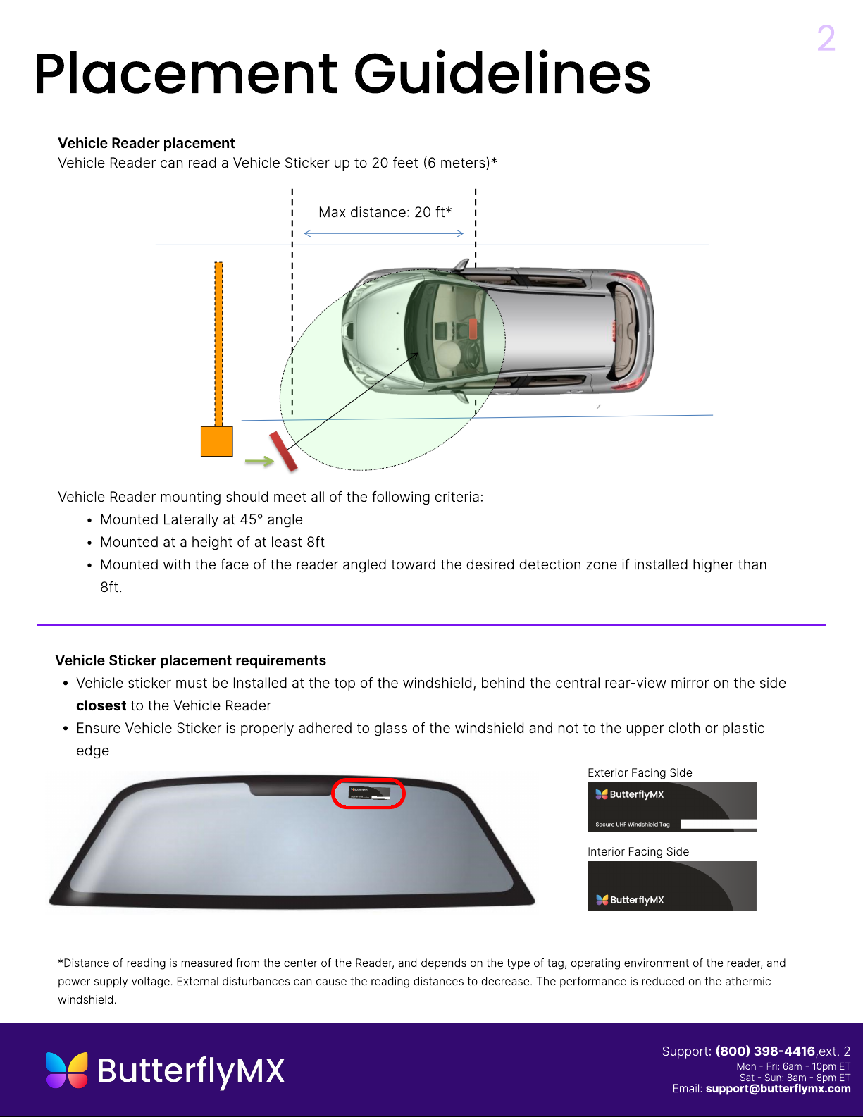
Identifying some basic details of the
installation will help determine the optimal
mounting location of the Vehicle Reader and
identify any potential issues or roadblocks
along the way.
K
ey information includes
D
imensions and positions of where the vehicles will be when their
V
ehicle Sticker is scanned by the
V
ehicle Reader.
(
i.e.
3’
from the
garage door on the left hand side of the 10
’
wide driveway
A
site map, or dimensions of parking entrance and exit area
The direction of the traffic flows in and out of the parking are
Types of vehicles entering the locked parking area
Popular Automobile Accessories manuals by other brands

Steinhof
Steinhof R-101 FITTING AND OPERATION MANUAL

FALCON RIDGE
FALCON RIDGE CF-19-Z-DRW01 Instructions for Installation and Care

ISRINGHAUSEN
ISRINGHAUSEN 6800/338 Bus Service manual

Sentinel
Sentinel CA52 Installation & operation

Dakota Digital
Dakota Digital VHX Series Installation

vipair
vipair TRL-12 instructions