11
IMPORTANT SAFETY INSTRUCTIONS
READ BEFORE OPERATING EQUIPMENT
02
POWER STATUS INDICATOR (Orange LED Fault Indicator)
If Power Status Indicator begins flashing orange, the amplifier has experienced a
problem and entered a fault mode.
THERMAL PROTECTION
This occurs if the amplifier’s internal temperature becomes too high. The Power
Status Indicator will change from Green to Blinking Orange, and output from
amplifier will stop. Once the internal temperature has lowered sufficiently, the
amplifier will resume normal operation and output.
OVERCURRENT PROTECTION
If there is an impedance issue with the transducer(s) attached to the output or with
the power voltage, the amplifier will enter this mode. The Power Status Indicator
will change from Green to Blinking Orange and output from amplifier will stop.
Remove the output connections from the amplifier. Check the wiring and
transducer(s) that were previously connected to the amplifier. Check the impedance
of the attached transducer(s) and wiring. Check AC power voltage. After the above
has been verified as correct, reconnect the transducer(s) and power then power
on the amplifier. If all is correct, the amplifier will resume normal operation and
output.
If the amplifier does not exit fault mode, remove all output and input connections
then power on the amplifier.
If the amplifier remains in the fault mode, contact support.
DC PROTECTION
If the input signal to the amplifier is too high and excessive clipping occurs, the
amplifier will enter this mode. The Power Status Indicator will change from Green
to Blinking Orange and output from amplifier will stop. Unplug the input connection
to the amplifier. Reset amplifier with the power button, lower amplifier volume.
Check the signal source and lower its output level as well if necessary.
Reconnect input connection. Amplifier will resume normal operation and output if
signal levels have been lowered sufficiently.
If the amplifier does not exit fault mode, remove all output and input connections
then power on amplifier.
If the amplifier remains in fault mode, contact support.
If the cause of the orange light is still unclear after reviewing this information,
remove power and disconnect all input and output connections from the amplifier.
Wait at least 30 minutes before reconnecting AC power and attempting to power
on again.
If the amplifier remains in fault mode, contact support.
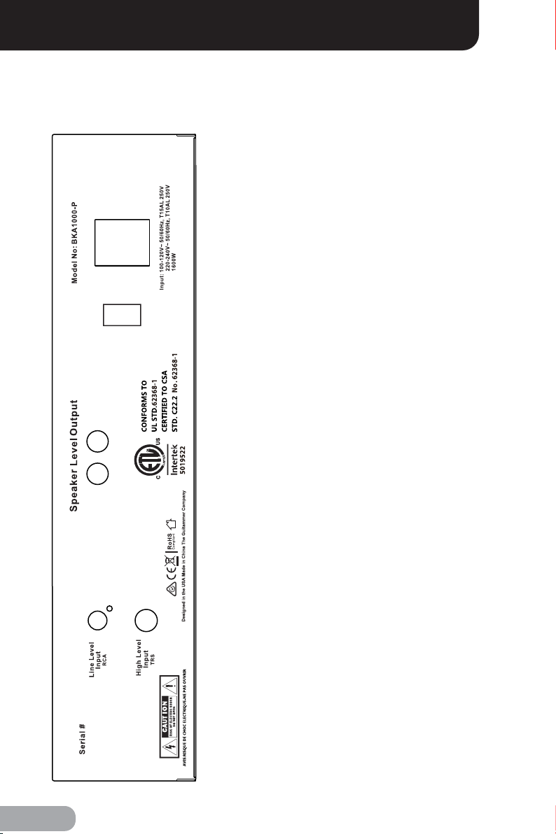
Power Amplifier BKA1000-P
1) Read these instructions.
2) Keep these instructions.
3) Heed all warnings.
4) Follow all instructions.
5) Do not use this apparatus near water.
6) Clean only with dry cloth.
7) Do not block any ventilation openings. Install in accordance with the manufacturer’s instructions.
8) Do not install near any heat sources such as radiators, heat registers, stoves, or other apparatus
(including amplifiers) that produce heat.
9) Do not defeat the safety purpose of the polarized or grounding-type plug. A polarized plug has two
blades with one wider than the other. A grounding type plug has two blades and a third grounding
prong. The wide blade or the third prong are provided for your safety. If the provided plug does not fit
into your outlet, consult an electrician for replacement of the obsolete outlet.
10) Protect the power cord from being walked on or pinched particularly at plugs, convenience
receptacles, and the point where they exit from the apparatus.
11) Only use attachments/accessories specified by the manufacturer.
12) Use only with the cart, stand, tripod, bracket, or table specified by the manufacturer, or sold with
the apparatus. When a cart is used, use caution when moving the cart/apparatus combination to
avoid injury from tip-over.
13) Unplug this apparatus during lightning storms or when unused for long periods of time.
14) Refer all servicing to qualified service personnel. Servicing is required when the apparatus has
been damaged in any way, such as power-supply cord or plug is damaged, liquid has been spilled or
objects have fallen into the apparatus, the apparatus has been exposed to rain or moisture, does not
operate normally, or has been dropped.
WARNING
Do not ingest the battery, Chemical Burn Hazard
(The remote control supplied with) This product contains a coin/button cell battery. If the coin/button
cell battery is swallowed, it
can cause severe internal burns in just 2 hours and can lead to death.
Keep new and used batteries away from children.
If the battery compartment does not close securely, stop using the product and keep it away from
children.
If you think batteries might have been swallowed or placed inside any part of the body, seek
immediate medical attention.