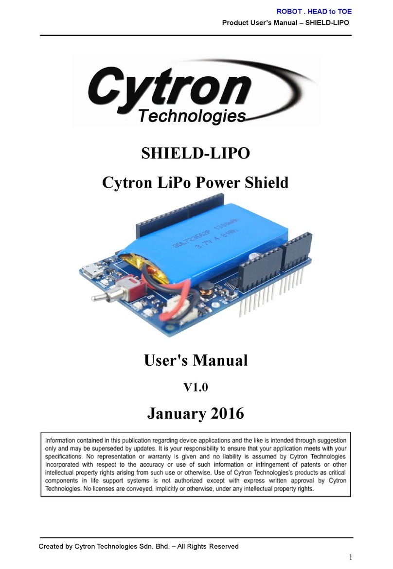
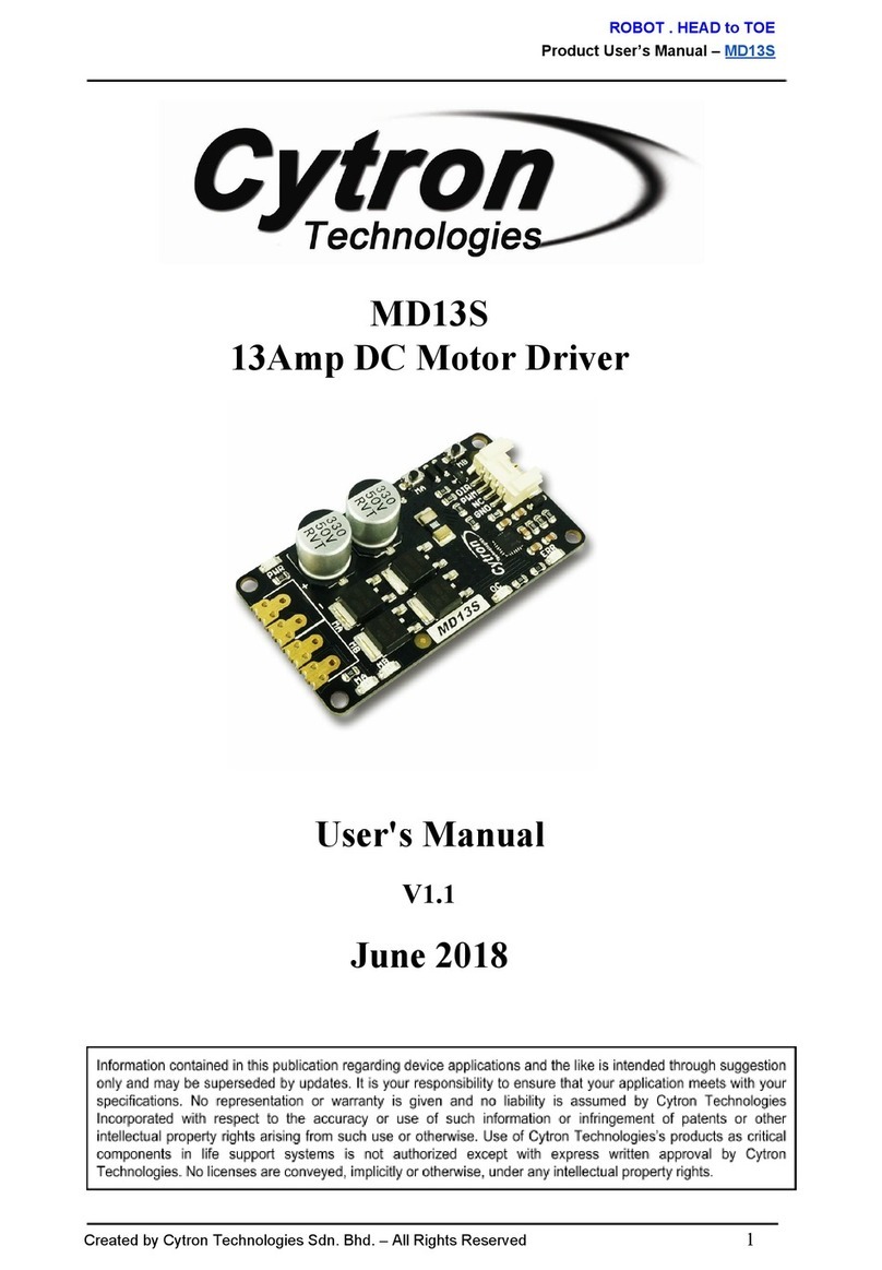
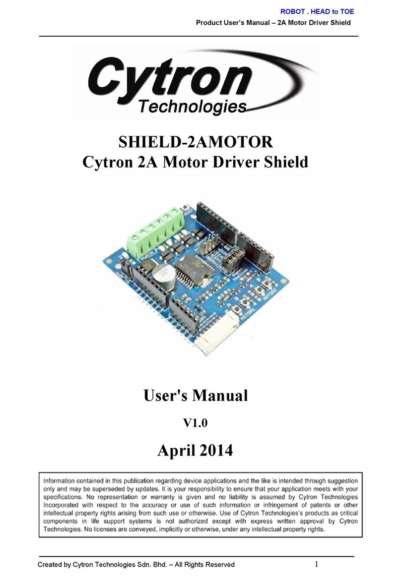
Cytron Technologies ESPWiFi Shield User manual

ROBOT.HEADtoTOE
ProductUser’sManual–ESPWiFiShieldRev2.0
Index
1. Introduction 3
2. PackingList 4
3. BoardorProductLayout 5
4. Dimension 7
5. UART/SerialCommunication 8
6. HardwareInstallation 9
7. GettingStarted 10
8. FirmwareInstallation 14
9. Warranty 14
CreatedbyCytronTechnologiesSdn.Bhd.–AllRightReserved 2

ROBOT.HEADtoTOE
ProductUser’sManual–ESPWiFiShieldRev2.0
1.0INTRODUCTION
ESPWiFi Shield Rev2.0 is an Arduino shield which integrates famous ESPWROOM02
WiFi module and provides low cost WiFi solution with any Arduino projects. It is compatible
with Arduino Uno, Arduino Duemilanove, Arduino Mega2560, Arduino Leonardo and
possiblyotherpincompatiblemainboards.
ESP8266 WiFi shield provides easy and stable UART interface for users to communicate
with onboard WiFi module using Arduino boards. The module is preloaded with AT firmware
and the user can use provided library to implement WiFi solution in their Arduino projects.
Advanced users can even customise and upload their own firmware on this ESP8266 module
and use it as an additional microcontroller to create an even more powerful application
togetherwithArduinoboards.
ESP8266 WiFi shield has stackable side headers which allows more Arduinocompatible
shields to be stacked on top of it. This shield provides digital pins options for software and
hardware UART or even PCESP communication. It also provides GPIO pin breakout and a
small prototyping area for the users to construct small circuits suitable to their application.
TheshieldalsocomeswithmicroSDslotwhichservesasextrafilestoragefortheusers.
Features:
●OnboardESPWROOM02WiFimodulewithpreloadedATfirmware
●JumperselectorsforsoftwareorhardwareUARTandPCESPcommunication.
●TXandRXLEDindicatorsforESP8266WiFimodule.
●ESP82663V3GPIOpinbreakout(including9digitalI/Opinsand1analoginputpin)
●Prototypingarea
●1MicroSDcardslot.
●ArduinoResetandESP8266ModuleResetbutton.
CreatedbyCytronTechnologiesSdn.Bhd.–AllRightReserved 3

ROBOT.HEADtoTOE
ProductUser’sManual–ESPWiFiShieldRev2.0
2.0PACKINGLIST
Pleasecheckthepartsandcomponentsaccordingtothepackinglists.Ifthereareanyparts
missing,pleasecontactusat[email protected]immediately.
1. 1xESPWiFiShield
2. 2xminijumper
CreatedbyCytronTechnologiesSdn.Bhd.–AllRightReserved 4

ROBOT.HEADtoTOE
ProductUser’sManual–ESPWiFiShieldRev2.0
3.0BOARDORPRODUCTLAYOUT
1.StackableDigitalI/Oheader
This header pin is Digital I/O pin stacked to the Arduino main board. Other Arduino shield
canbestackedontopofthisstackableheader.
2.StackableAnalogInputpinheader
This header pin is Analog Input pin stacked to the Arduino main board. Other Arduino shield
canbestackedontopofthisstackableheader.
3.MicroSDcardchipselect(CS)
Digital Pin 4 is used as chip select for MicroSD card. Do not make any other connection to
thispin.
4.RXPinSelector
User may select D0, D2, D8, D10 and D12 as the RX pin from Arduino main board with the
minijumper.
5.TXPinSelector
User may select D1, D3, D9, D11 and D13 as the TX pin from Arduino main board with the
minijumper.
6.ArduinoResetbutton
ResetbuttonisforconvenienceofusertoresettheArduinomainboard.
CreatedbyCytronTechnologiesSdn.Bhd.–AllRightReserved 5

ROBOT.HEADtoTOE
ProductUser’sManual–ESPWiFiShieldRev2.0
7.ESPResetbutton
ResetbuttonisforconvenienceofusertoresettheonboardESP8266module.
8.Flash/Runslideswitch
Slide switch is for convenience of user to select which mode ESP8266 module will enter
oncepoweredup.
FlashmodethemodewhichESP8266modulewaitforfirmwareinstallation/update
RunmodethemodewhichESP8266moduleruntheinstalledfirmware
9.ESP3V3GPIObreakout
Pin breakout from ESP8266 GPIO, consists of 9 Digital I/O pins and 1 Analog Input pin. All
pinsare3.3Vtolerantonly.
10.PrototypingArea
Prototypingareaforuserstoconstructsmallcircuitssuitabletotheirapplications.
11.PowerLED
Power indicator LED for onboard ESP8266 module. The LED will turn on when 5V power is
suppliedtothemodule.
12.RXIndicatorLED
RXLEDasindicatorforRXsignalfromESP8266.
13.TXIndicatorLED
TXLEDasindicatorforTXsignalfromESP8266.
CreatedbyCytronTechnologiesSdn.Bhd.–AllRightReserved 6

ROBOT.HEADtoTOE
ProductUser’sManual–ESPWiFiShieldRev2.0
5.0UART/SERIALCOMMUNICATION
AT firmware of the ESP8266 WiFi module on ESPWiFi shield allows users to communicate
withthemoduleusingUARTcommunication.
Defaultsettingsare9600kbpsbaudrate,8bitdata,1stopbitandnoparity.
5.1GuidelineforsettingupTXandRXpinwithArduinoBoards
ThefollowingtableshowssuitableRXandTXpinstobechosenforcompatibleArduino
boards.
UART
ArduinoBoards
RX
TX
USB*
USB*
ArduinoUno/ArduinoMega/ArduinoLeonardo
D0
D1
ArduinoUno/ArduinoMega/ArduinoLeonardo
D2
D3
ArduinoUnoonly
D8
D9
ArduinoUno/ArduinoLeonardo
D10
D11
ArduinoUno**/ArduinoMega/ArduinoLeonardo
D12
D13
ArduinoUno**/ArduinoMega
*ThisoptionenablescommunicationbetweenESP8266moduleandPCusingsuitable
UARTsoftwaresuchasArduinoSerialMonitor,Hyperterminal,RealTermetc.
**OnlyapplicableifnoSPIcommunicationisusedbecauseSPIpinoutsusesD10D13
inArduinoUno.MicroSDcardcannotbeusedaswellinthiscase.
CreatedbyCytronTechnologiesSdn.Bhd.–AllRightReserved 8

ROBOT.HEADtoTOE
ProductUser’sManual–ESPWiFiShieldRev2.0
6.0HARDWAREINSTALLATION
This section will show example installation of ESPWiFi Shield with Arduino Uno as a main
controller. Besides Arduino Uno, other Arduino main boards such as Arduino Duemilanove,
CTUNO,ArduinoMega2560andCIKUarealsocompatiblewiththisshield.
6.1ArduinoUno
Arduino is an opensource physical computing platform based on a simple I/O board and a
development environment that implements the Processing/Wiring language. ESPWiFi Shield
can be used together with Arduino Uno. Figure below shows example hardware connection
between Arduino Uno and ESPWiFi Shield; it is simply stacking up the shield onto the
Arduinomainboard.
1. Set TX and RX pin for ESPWiFi Shield. The selection is done by using mini jumper
onboard.PleaserefertoSection5.1forsuitableRXandTXpinselection.
2. Please be cautious to initialize the correct Arduino’s digital pin in coding/software
according to the selected TX and RX pins for the communication. We recommend
usertousesoftwareserial(D3TX,D2RX)insteadofhardwareserial.
3. StackESPWiFiShieldonArduinoUno.Ensurethatthepinsalignmentiscorrect.
CreatedbyCytronTechnologiesSdn.Bhd.–AllRightReserved 9

ROBOT.HEADtoTOE
ProductUser’sManual–ESPWiFiShieldRev2.0
7.0GETTINGSTARTED
ThissectionwillshowexamplesofusingESPWiFiShieldtogetherwithArduinoBoardto
1) performATtestbasicmoduletestingbysendingATcommands
2) createasimpleWiFiserver
7.1ATTest
1. Stack ESPWiFi Shield onto compatible Arduino Board. For this example, Arduino
Unoisused.
2. Select USB for both RX and TX pins. **Note: This setting is only for entering AT
command.
3. MakesuretheslideswitchisswitchedtoRUNmode.
4. **Note: For AT Test, connect RST pin to GND using jumper wire. (Another
alternative, upload an empty sketch to Arduino main board before stacking
ESPWiFiShieldontoArduinoboard.)
5. ConnectArduinoboardtoPCusingUSBcable.
6. OpenArduinoIDE.DeterminewhichCOMportArduinoUnoisconnectedtoand
configuretheportsettingsundermenuTools>Port.
7. OpenandsetupArduinoSerialMonitorwithsettingsbelow.
● 9600Baud
● BothNL&CR
8. Figurebelowshowssending“AT”usingArduinoSerialMonitor.Iftheresultreturns
“OK”,itmeansyouhavesuccessfullycommunicatewiththeESP8266moduleon
ESPWiFiShield,ATtestissuccessful.UsercanalsotryoutotherATcommandslike
AT+GMR,etc.
CreatedbyCytronTechnologiesSdn.Bhd.–AllRightReserved 10

ROBOT.HEADtoTOE
ProductUser’sManual–ESPWiFiShieldRev2.0
7.2CreateasimpleWiFiserverusingArduinoUno+ESPWiFiShield
1. Stack ESPWiFi Shield onto compatible Arduino Board. For this example, Arduino
Unoisused.
2. SelectD2forRXandD3forTXpin.
3. MakesuretheslideswitchisswitchedtoRUNmode.
4. Download CytronWiFiShield library from link provided at product page and extract
thefilestoMyDocuments>Arduino>Libraries.
CreatedbyCytronTechnologiesSdn.Bhd.–AllRightReserved 11

ROBOT.HEADtoTOE
ProductUser’sManual–ESPWiFiShieldRev2.0
5. ConnectArduinoboardtoPCusingUSBcable.
6. OpenArduinoIDE.DeterminewhichCOMportArduinoUnoisconnectedtoand
configuretheportsettingsundermenuTools>Port.
7. Go to File > Examples > CytronWiFiShield and open example sketch
CytronWiFiDemo.
8. Changessidfrom“...”toyournetworknameand“pass”tocorrespondingpassword.
Forexample,yournetworkrouterSSIDisWiFlyandpasswordisabcd.
constchar*ssid="WiFly";
constchar*pass="abcd";
9. Check the line wifi.begin(2, 3). 1st argument for this function refers to RX of Arduino
and 2nd refers to TX. If D2 is selected for RX and D3 for TX on ESPWiFi Shield, the
configurationiscorrect.
10. UploadtheprogramtoArduinoboard.
11. OpenArduinoSerialMonitortoviewtheprogress.Setupto9600baud.
12. MakesurePCisconnectedtothesameinternetnetworkwiththeESPWiFiShield.
13. Observe the IP Address shown in Serial monitor. Enter the IP Address using any web
browsers(GoogleChrome,MozillaFirefox,etc.)
CreatedbyCytronTechnologiesSdn.Bhd.–AllRightReserved 12

ROBOT.HEADtoTOE
ProductUser’sManual–ESPWiFiShieldRev2.0
14. If the webpage returns what have shown in the following figure, the program is
working.Fortheexamplehere,IPaddressshowninSerialmonitoris192.168.1.242.
CreatedbyCytronTechnologiesSdn.Bhd.–AllRightReserved 13

ROBOT.HEADtoTOE
ProductUser’sManual–ESPWiFiShieldRev2.0
8.0FIRMWAREINSTALLATION
ESP8266 3V3 GPIO Input and Output function has deprecated with preloaded AT firmware
on ESPWROOM02 module on ESPWiFi Shield. However, Cytron Technologies offers
customised AT firmware which adds the stated capibility to the module, allowing user to
utilise the 3V3 GPIO fully in the applications. User can follow the guide below to install new
ATfirmwaretothemodule.
Hardwareconfiguration
1. Stack the shield onto Arduino compatible board. In this example, Arduino Uno is
used.
2. PlacebothminijumpersonUSBselection.
3. **IMPORTANT!! Connect RST to GND using jumper wire to make sure the board
reset at all times (Another alternative, upload an empty sketch to Arduino Uno before
stackingtheshieldontoit)
4. SlidetheslideswitchtoFLASHmode.
5. Connectthewholeboard(ArduinoUno+ESPWiFishield)toPCviaUSBcable.
6. Press ESP Reset button (with slide switch switched to FLASH mode) to enable
CreatedbyCytronTechnologiesSdn.Bhd.–AllRightReserved 14

ROBOT.HEADtoTOE
ProductUser’sManual–ESPWiFiShieldRev2.0
FLASHmodeofESPWROOM02module.
InstallATFirmware
● Windows(forWindowsuseronly)
1. Download latest ESPWIFI_Shield_Firmware from link provided at product
page.Extractit.Enterthefolder,gotoinstall_firmware>windows.
2. OpenESP_DOWNLOAD_TOOL_V2.4.exe.
3. ChoosetheCOMportArduinoUno+ESPWiFishieldconnectingto.
4. Make sure ESPWROOM02 module is in FLASH mode (step 4 and 6 in
HardwareConfiguration)
5. ClickSTARTtoinstallthefirmware.
● Linux(forLinuxuseronly)
1. Download latest ESPWIFI_Shield_Firmware from link provided at product
page.Extractit.Enterthefolder,gotoinstall_firmware>linux.
2. Make sure ESPWROOM02 module is in FLASH mode (step 4 and 6 in
HardwareConfiguration)
3. Openterminalhereandrunfollowinglinetostartfirmwareinstallation.
$./flash.sh<theportArduinoUno+ESPWiFishieldconnectingto>
E.g$./flash.sh/dev/ttyACM0
ATTestandsomeminorconfiguration
1. Open Arduino Serial Monitor. Make sure the serial port is same as the port Arduino
Uno+ESPWiFishieldconnectingto.
2. OpenandsetupArduinoSerialMonitorwithsettingsbelow.
● 115200Baud
● BothNL&CR
3. SwitchtheslideswitchtoRUNmode.
4. Press ESP reset button. If there is a word “ready” shown in monitor, the firmware
installationissuccessfulandthefirmwareisworkingproperly.
5. EnterthecommandAT+UART=9600,8,1,0,0
6. Afterthemonitorshows“OK”inreturn,changeto9600Baud.
7. Test the module with several commands like AT and AT+GMR. If there are replies
fromthesecommands,UARTsetupissuccessful.
8. The shield is now ready for WiFi library implementation. Remember to switch TX
andRXjumperstoD2andD3orotherpairsaccordingtoyourarduinosketch.
CreatedbyCytronTechnologiesSdn.Bhd.–AllRightReserved 15

ROBOT.HEADtoTOE
ProductUser’sManual–ESPWiFiShieldRev2.0
9.0WARRANTY
●Productwarrantyisvalidfor6months.
●Warrantyonlyappliestomanufacturingdefect.
●Damagedcausedbymisuseisnotcoveredunderwarranty
●Warrantydoesnotcoverfreightcostforbothways.
Preparedby
CytronTechnologiesSdn.Bhd.
No.16,JalanIndustriRinganPermatangTinggi2,
KawasanIndustriRinganPermatangTinggi,
14100SimpangAmpat,
Penang,Malaysia.
Tel: +6045041878
Fax: +6045040138
CreatedbyCytronTechnologiesSdn.Bhd.–AllRightReserved 16

ROBOT.HEADtoTOE
ProductUser’sManual–ESPWiFiShieldRev2.0
URL: www.cytron.com.my
Email:[email protected]
CreatedbyCytronTechnologiesSdn.Bhd.–AllRightReserved 17
Table of contents
Other Cytron Technologies Computer Hardware manuals