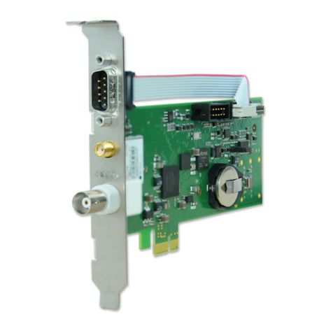
Meinberg IMS-LNO User manual

SETUP GUIDE
IMS-LNO
Hot-Plug Module
October 24, 2022
Meinberg Funkuhren GmbH & Co. KG


Table of Contents
1 Imprint 1
2 Introduction 2
3 Important Safety Information 3
3.1 ProductDocumentation ........................................... 3
3.2 PreventionofESDDamage......................................... 4
3.3 PowerSupply................................................. 5
3.4 Cabling..................................................... 5
4 Front Connectors IMS-LNO 6
4.1 IMS-LNO-StatusLEDs .......................................... 7
4.2 10MHzsineOutput............................................. 8
5 Before You Start 10
5.1 ContentsofDelivery............................................. 10
5.2 DisposalofPackagingMaterials...................................... 10
6 System Installation 11
6.1 Important Information Regarding Hot-Pluggable IMS Modules . . . . . . . . . . . . . . . . . . . . 11
6.2 Installation and Removal of Hot-Pluggable IMS Modules . . . . . . . . . . . . . . . . . . . . . . . 12
7 Status Monitoring of the IMS-LNO 14
8 RoHS and WEEE 15
Date: October 24, 2022 IMS-LNO

1 Imprint
1 Imprint
Meinberg Funkuhren GmbH & Co. KG
Lange Wand 9, 31812 Bad Pyrmont, Germany
Phone: + 49 (0) 52 81 / 93 09 - 0
Fax: + 49 (0) 52 81 / 93 09 - 230
Website: https://www.meinbergglobal.com
Email: [email protected]
Date: October 24, 2022
IMS-LNO Date: October 24, 2022 1

2 Introduction
This Setup Guide is a systematically structured guideline which supports you during the set-up of your Mein-
berg product.
The IMS-LNO is a 10 MHz generator card and provides sinewave signals with low phase noise at four outputs.
It has a microprocessor system which monitors the output signals and generates status signals for the manage-
ment system.
Functionality
A high-quality oscillator is synchronized by the 10 MHz signal of the external reference clock and thus provides
the high-precision clock for the IMS-LNO. The microprocessor monitors the lock state of the PLL synchro-
nization circuit and the warm-up phase of the oscillator and only enables the outputs after a successful phase
synchronisation. This state is also indicated by the four status LEDs (transition from red to green). In the
phase synchronous state, the output level of the four outputs is monitored and in case of an error is signaled
by the assigned red LED.
The LANTIME firmware manual provides a complete description of all configurations and status monitoring
options of your Meinberg product.
Download link: https://www.meinbergglobal.com/download/docs/manuals/english/ltos_7-00.pdf
Compatibility
The IMS-LNO is an IMS module which is compatible with all systems of the IMS family. It can also be
used on any slot (MRI, ESI, I/O).
2 Date: October 24, 2022 IMS-LNO

3 Important Safety Information
Please ensure that IMS modules designed for "hot-plugging" (modules that are removable and insertable while
a system is in operation) are always handled with the utmost care.
Before performing any maintenance work on the system:
•We recommend making a backup of any stored configurations (e.g. using a USB flash drive or from the
Web UI)
•Take note of the chapter "Prevention of ESD Damage".
•Take note of the chapter "Power Supply".
3.1 Product Documentation
Detailed product documentation is provided on a USB flash drive delivered with the Meinberg system. The
manuals can also be downloaded from the Meinberg website at https://www.meinbergglobal.com, where you can
enter your system name into the search box at the top of the page to find the relevant manual. Alternatively,
contact Meinberg Support for further assistance.
The "Docs & Support" menu on the Web Interface also provides user manuals for time server administrators.
This manual contains important safety instructions for the installation and operation of the
device. Please read this manual thoroughly before using the device.
This device may only be used for the purpose described in this manual. In particular, the
specified operating limits of the device must be heeded. The person setting up the device is
responsible for safety matters in relation to any larger system in which the device is
installed!
Failure to observe these instructions may have an adverse impact on device safety!
Please keep this manual in a safe place.
Target Readership
This manual is only intended to be used by qualified electricians, or by persons who have been appropri-
ately instructed by a qualified electrician and who are familiar with applicable national standards and with
safety rules & regulations. This device may only be installed, set up, and operated by qualified personnel.
IMS-LNO Date: October 24, 2022 3

3.2 Prevention of ESD Damage
ATTENTION!
An ESDS device (electrostatic discharge-sensitive device) is any device at risk of damage or
malfunction due to electrostatic discharges (ESD) and thus requires special measures to prevent
such damage or malfunction. Systems and modules with ESDS devices usually bear the following
symbol:
Symbol Indicating Devices with ESDS Components
The following measures will help to protect ESDS components from damage and malfunction.
When preparing to dismantle or install devices:
Ground your body (for example, by touching a grounded object) before touching sensitive devices.
Ensure that you wear a grounding strap on your wrist when handling such devices. These straps must
in turn be attached to an uncoated, non-conductive metal part of the system.
Use only tools and devices that are free of static electricity.
When transporting devices:
Devices must only be touched or held by the edges. Never touch any pins or conductors on the device.
When dismantling or installing devices:
Avoid coming into contact with persons who are not grounded. Such contact may compromise your
connection with the earth conductor and thus also compromise the device’s protection from any
static charges you may be carrying.
When storing devices:
Always store devices in ESD-proof ("antistatic") bags. These bags must not be damaged in any way.
ESD-proof bags that are crumpled or have holes cannot provide effective protection against
electrostatic discharges.
ESD-proof bags must have a sufficient electrical resistance and must not be made of conductive
metals if the device has a lithium battery fitted on it.
4 Date: October 24, 2022 IMS-LNO

3 Important Safety Information
3.3 Power Supply
WARNING!
The IMS system in which the module is used is operated at a dangerous voltage. Please
refer to your IMS Manual for more information about safety.
When removing a hot-pluggable power supply unit, always disconnect its power cable before
removing it from the IMS system.
Never open a power supply unit—there may still be hazardous residual voltages
present even after disconnection from the mains supply. In the event that a power supply
unit is no longer working (e.g. defective), please return it to Meinberg for repair.
Failure to observe these safety instructions may result in serious injury and/or property
damage. The IMS system must only be installed, set up, and operated by qualified
personnel.
3.4 Cabling
WARNING!
Danger of death from electric shock! Never work on cables while the power is live!
Always disconnect the cables from the devices at both ends before working on
the plugs and terminals of connected cables!
IMS-LNO Date: October 24, 2022 5

4 Front Connectors IMS-LNO
2
1
6 Date: October 24, 2022 IMS-LNO

4 Front Connectors IMS-LNO
4.1 IMS-LNO - Status LEDs
Status display
LED St: Status of the IMS-LNO
LED In: Status of the backplane output signals
LED A: Status of the LNO output signals (A)
LED B: Status of the LNO output signals (B)
St In A B
The status messages of the LED’s are as follows:
LED St:
Blue During initialization
Green During operation
LED In.
Green 10 MHz reference available, PLL is locked
Yellow 10 MHz reference available, PLL is not yet locked
Red 10 MHz reference not recognized or insufficient signal quality
LED A - Status output 1-2
1 sec red -> 1 sec yellow -> 1 sec green -> 1 sec off
Green 10 MHz signal available at both outputs
Red No 10 MHz signal or short circuit at one of the two outputs
LED B - Status output 3-4
1 sec Red -> 1 sec Yellow -> 1 sec Green -> 1 sec Off
Green 10 MHz signal available at both outputs
Red No 10 MHz signal or short circuit at one of the two outputs
The output cannot be active before the PLL is locked.
IMS-LNO Date: October 24, 2022 7

4.2 10 MHz sine Output
Output signal: 10 MHz sine frequency
Signal level: 5 dBm +/- 1 dBm at 50 Ω
Optional 8 dBm +/- 1 dBm at 50 Ω
Signal level: 12 dBm +/- 1 dBm at 50 Ω
Port to port isolation: 45 dB
Harmonic harmonics: < -60 dBc
Non-harmonic
harmonics: < -65 dBc
Phase noise:
OCXO-SQ < 1 Hz -80 dBc/Hz
< 10 Hz -100 dBc/Hz
< 100 Hz -130 dBc/Hz
< 1 kHz -140 dBc/Hz
< 10 kHz -150 dBc/Hz
OCXO-MQ < 1 Hz -85 dBc/Hz
< 10 Hz -110 dBc/Hz
< 100 Hz -135 dBc/Hz
< 1 kHz -143 dBc/Hz
< 10 kHz -155 dBc/Hz
OCXO-HQ < 1 Hz -93 dBc/Hz
< 10 Hz -126 dBc/Hz
< 100 Hz -140 dBc/Hz
< 1 kHz -145 dBc/Hz
< 10 kHz -165 dBc/Hz
Power supply: 5 dBm +5 V @ 550 mA (steady state),
+5 V @ 670 mA (warm up)
8 dBm +5 V @ 720 mA (steady state),
+5 V @ 640 mA (warm up)
12 dBm:+5 V @ 970 mA (steady state),
+5 V @ 620 mA (warm up)
Connection type: BNC socket
Cable: coaxial, shielded
8 Date: October 24, 2022 IMS-LNO

4 Front Connectors IMS-LNO
Method
The internal 10 MHz reference signal is fed into a narrow band quartz filter. The generated signal will be
provided to up to four outputs via a distribution amplifier circuit.
Input Buffer
Matching
Circuit
10 MHz
Quartz Filter Output
Amplifier
Internal 10 MHz
10 MHz, Sine Wave
Reference Oscillator
Matching
Circuit Output
Amplifier 10 MHz, Sine Wave
Output
Amplifier 10 MHz, Sine Wave
Output
Amplifier 10 MHz, Sine Wave
IMS-LNO Date: October 24, 2022 9

5 Before You Start
5.1 Contents of Delivery
Unpack the IMS-LNO carefully and check the contents of the delivery against the enclosed packing list to
ensure that no parts are missing. If any of the listed items are missing, please contact our sales department:
Check that the product has not been damaged in transit. If the product is damaged or fails to operate upon
installation, please contact Meinberg immediately. Only the recipient (the person or company receiving the
system) may file claims or complaints against the forwarder for damage caused in transit.
Meinberg recommends that you keep the original packaging materials in case the product needs to be shipped
or transported again at a later date.
5.2 Disposal of Packaging Materials
The packaging materials we use are fully recyclable:
Material Used for Disposal
————————————————————————————————————————
Cardboard Shipping, Paper recycling
packaging of accessories
Plastic Wrapping Shipping, Household waste or
packaging of accessories recycling depot
————————————————————————————————————————
10 Date: October 24, 2022 IMS-LNO

6 System Installation
6.1 Important Information Regarding Hot-Pluggable IMS Modules
The following information should be strictly observed when replacing IMS modules during operation. Not all
IMS modules are fully hot-pluggable. For example, it is naturally not possible to replace a power supply unit in
a system without PSU redundancy without first having installed a second power supply unit while the system
is in operation.
The following rules apply for the individual IMS slots:
PWR Slot: "Hot-Swappable" If you operate your system with only one power supply unit, a
second power supply unit must be installed before removing
or replacing it in order to keep your system on.
I/O, ESI and
MRI Slots: "Hot-Pluggable".
CLK1/CLK2 "Hot-Pluggable" When a clock module is replaced or installed, it is important to
Slots: rescan the reference clocks ("Rescan Refclocks") in the
"System" menu of the Web Interface.
RSC/SPT Slots: "Hot-Pluggable" It will not be possible for your IMS system to switch between
signal generators while the RSC/SPT is not installed.
——————————————————————————————————————————————
CPU Slot: "Not Hot-Pluggable" Before the CPU is removed, the IMS system must be powered
down.
Please note that after powering on and rebooting the LANTIME
Operating System, the configuration of some IMS modules may
be reset to factory defaults!
Information:
The NTP service and access to the web interface will be unavailable while the CPU is not installed.
Management and monitoring functions will also be disabled.
IMS-LNO Date: October 24, 2022 11

6.2 Installation and Removal of Hot-Pluggable IMS Modules
A Torx screwdriver is required (T8 x 60) to remove and install IMS modules.
Important!
Heed the safety information at the beginning of this manual!
Removing a Module
1. Remove the two marked Torx screws from the
module holder plate.
2. Pull the module carefully out of the
guide rail. Note that the module will be
securely seated in the connector block inside
the chassis—a certain amount of force must
be applied to release the module. Once the
module has been detached from the connector
block on the system backplane, the module can
be easily pulled out.
3. If the removed module is not to be replaced
with another module, the cover plate should
be refitted using the two Torx screws.
Locations of fixture screws in a 1RU IMS system
12 Date: October 24, 2022 IMS-LNO

6 System Installation
Installing a Module
1. If a module is to be replaced, remove the installed module in accordance with the guide "Removing a
Module" on the previous page. Otherwise, remove the two Torx screws from the cover plate of the
unused slot. We recommend keeping the cover plate in a safe place for later use.
2. Insert the module correctly into the two guide rails of the system chassis. If the module cannot be
inserted with minimal force, it is possible that the module is not properly seated in the guide rails.
In this case, you should pull the module out and try again. Do not use excessive force to try and push
the module in! Failure to heed this instruction may result in damage to the module and/or chassis.
3. Once the module has reached the connector block of the system backplane, a little more force will be
required to insert the module into the connector block. Ensure that the module is locked securely into
place and that the faceplate of the module is flush with that of the adjacent modules or cover plates.
4. Insert and tighten the two Torx screws again.
The installed module is now ready to set up for use.
IMS-LNO Date: October 24, 2022 13

7 Status Monitoring of the IMS-LNO
The status menu provides detailed status monitoring options for the IMS-LNO. To do so, select the menu I/O-
Config –> Status in the web interface.
All values monitored by the microprocessor of the IMS-LNO are displayed here in detail.
Reference values:
A comparison of the expected voltage values at the respective power levels is given below.
dBm Vpp
5 dBm Variante (5 dBm +/- 1) 4 1,0 V
5 1,1 V
6 1,3 V
————————————————————————-
8 dBm Variante (8 dBm +/- 1) 7 1,4 V
8 1,6 V
9 1,8 V
————————————————————————-
12 dBm Variante (12 dBm +/- 1) 11 2,2 V
12 2,5 V
13 2,8 V
14 Date: October 24, 2022 IMS-LNO

8 RoHS and WEEE
8 RoHS and WEEE
Compliance with EU Directive 2011/65/EU (RoHS)
We hereby declare that this product is compliant
with the European Union Directive 2011/65/EU and
its delegated directive 2015/863/EU “Restrictions of
Hazardous Substances in Electrical and Electronic
Equipment”. We ensure that electrical and electronic
products sold in the EU do not contain lead, cad-
mium, mercury, hexavalent chromium, polybrominated
biphenyls (PBBs), polybrominated diphenyl ethers
(PBDEs), bis(2-ethylhexyl)phthalat (DEHP), benzyl
butyl phthalate (BBP), dibutyl phthalate (DBP), or
diisobutyl phthalate (DIBP) above the legal limits.
WEEE status of the product
This product is handled as a B2B (Business to Busi-
ness) category product. To ensure that the product is
disposed of in a WEEE-compliant fashion, it can be
returned to the manufacturer. Any transportation ex-
penses for returning this product (at end-of-life) must
be covered by the end user, while Meinberg will bear
the costs for the waste disposal itself.
IMS-LNO Date: October 24, 2022 15
Table of contents
Other Meinberg Computer Hardware manuals

Meinberg
Meinberg BPE-2000 User manual

Meinberg
Meinberg GPS167PC User manual

Meinberg
Meinberg GPS180PEX User manual

Meinberg
Meinberg TCR510PCI User manual

Meinberg
Meinberg GNS181PEX User manual

Meinberg
Meinberg GPS170PEX User manual

Meinberg
Meinberg Line InterfaceUnit v2.0 User manual

Meinberg
Meinberg TCR180PEX-EL User manual

Meinberg
Meinberg TCR180 User manual

Meinberg
Meinberg GPS170PCI User manual