UNINSTALL HITCH
UNATTACHING TRAILER
Lower landing gear and block the trailer wheels. Raise
the trailer until the tongue weight is removed from the
truck. Then, unpin the Coupler handle and rotate to the
open position to unlatch the jaws. If the jaws do not open,
readjusting the landing gear may relieve pressure and
allow them to open. Use the safety pin to lock the handle
in the open position and when you are sure that the
landing gear will support the trailer, move the truck
forward to release the jaws from the kingpin. The jaws
will always open when the pressure of the trailer is taken
off the Coupler as the truck pulls away.
Have the truck stationary with the emergency brake on,
the trailer wheels blocked and landing gear still resting
firm on the ground supporting the weight of the trailer.
Make sure no one is between the truck and trailer, return
to the cab of the truck. Release the emergency brake and
apply the trailer brakes. Try to pull the trailer forward with
the truck. If the trailer is properly hooked up, the wheel
blocks and trailer brakes should not allow the truck to
move forward. If trailer is not hitched correctly, the trailer
will separate from the truck. However, with the landing
gear resting firmly on the ground, it will support the trailer
and not allow it to drop or fall on the truck sides.
PULL TEST
Remove the coupler cam handle safety pin and rotate
the cam handle to the open position. Adjust the height
of the 5th wheel trailer so that the king pin plate is
slightly lower than the top of the coupler. Back the
truck towards the trailer, centering the trailers king pin
in the Coupler, until the king pin has engaged the
jaws. Ensure that the Coupler cam handle has
completely closed before inserting the cam handle
safety pin through the cam handle and the coupler.
Hook up brake and lighting connections before towing.
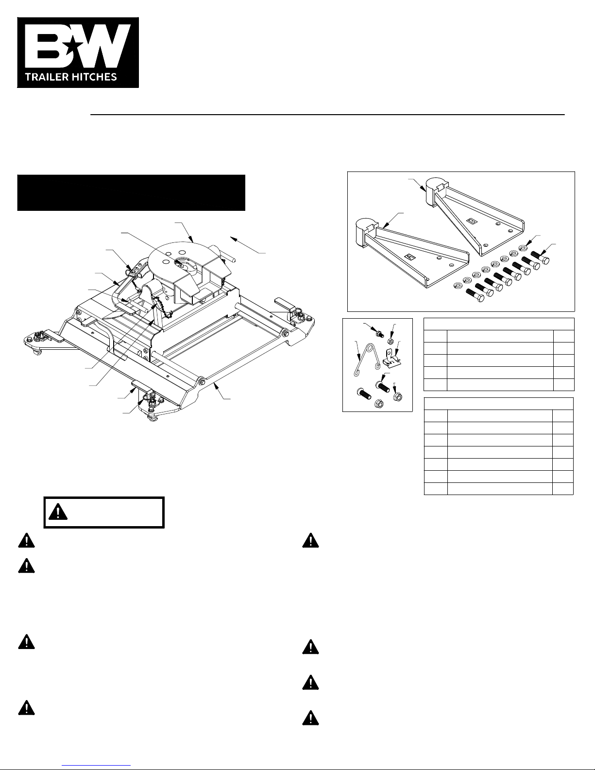
ATTACHING TRAILER
Adjust the resting angle of
your coupler plate by rotating
the spring on the driver side
pivot arm. Pulling the top of
the spring away from the cab
will increase the angle of the
coupler plate. Set the angle of
the coupler so that head will
tilt away from the cab when
coupling, see Figure F1. Tighten
the 1/4" nut once the spring’s orientation is set.
Lubricate the polyurethane bushings on top of pivot
arms with high grade lithium grease (available at your
local hardware/automotive store). Place the coupler
over the pivot arms. (The saddle handles should be
parallel with the Slider Base in the latched position.)
Place the saddle lock pins through the saddle, then
insert the hair pins through the holes in the end of the
saddle lock pins to secure the coupler to the pivot arms.
2.
1.
INSTALL COUPLER HANDLE
Locate the two 3/8" x 1−1/4" button head cap screws
and the two 3/8" flanged lock nuts provided in a bolt
bag. Pull out the coupler arm and pin it with the
safety locking pin near the base of the arm as shown
in Figure E1.
1.
CAUTION: Pulling the arm out away from the coupler
creates a pinch point. Use caution when installing the
handle to avoid injury.
Using the button cap screws and the lock nuts, attach
the coupler handle to the arm and tighten, see Figure
E1. Pull out the coupler cam handle safety pin.
INSTALL COUPLER
To uninstall the Companion hitch, remove the saddle lock
pins, grab the saddle handles and lift to remove the
coupler from the pivot arms. To remove the Companion
base, remove the latch pins from each base leg and turn
the handles. Carefully lift and position the base out of the
attachment points.
NOTICE: Base latch handle tension and all bolted
connections should be checked regularly. The latches
must have the proper resistance when rotating, and bolts
must have proper torque. Always perform a visual
inspection before towing.
®®
WARNING: Do not use the Companion 5th wheel
hitch with any device that changes the location of the
king pin pivot point. The king pin on your trailer must
rotate in the jaws of the Companion Coupler, see
Figure G3. Preventing the king pin from rotating
within the jaws of the Companion Coupler with a
wedge, see Figure G4, or any other device, such as a
Reese Sidewinder or Reese Revolution , could
result in property damage, serious injury or death.
Reese is a registered trademark of Cequent Performance Products.
®
PAGE 4 of 5
Figure F1: Cutaway view of
driver side pivot arm and saddle.
Figure E1: View looking down at side of coupler head.
FIGURE G3:
Top view of coupler head.
FIGURE G4:
Coupler Head with
locking wedge.
3/8" LOCKING FLANGE NUTS
COUPLER ARM
COUPLER CAM
HANDLE SAFETY PIN
COUPLER
HANDLE
3/8" BUTTON HEAD
CAP SCREWS
KING PIN
PIVOT POINT
WEDGE