bwa DiREX-Pro.40 User manual

www.bwatech.com
DiREX-Pro
Digital Network Video Recorder / DVR
(specialised computer for video and audio surveillance)
This issue covers the following models:
DiREX-Pro.40
DiREX-Pro.120
DiREX-Pro.A30
DiREX-Pro.F16
Instruction Manual
Firmware Revision: 0.1950

Dear Customer
Thank you for purchasing this bwa product. To ensure many years of
safe and trouble-free operation of this high-tech device, please read
this manual before use. Please note that basic knowledge network and
Windows administration is necessary in order to use this product.
To prevent accidents and damage, read the Safety Warning (section
1.1) and Operation Conditions (section 8.1).
Table of Contents
1. Introduction.................................................................................................................4
1.1 Safety Warning.................................................................................................................................. 4
1.2 General Information ......................................................................................................................... 5
1.3 List of Contents ................................................................................................................................ 5
1.4 DiREX-Pro.A30 and DiREX-Pro.F16................................................................................................ 6
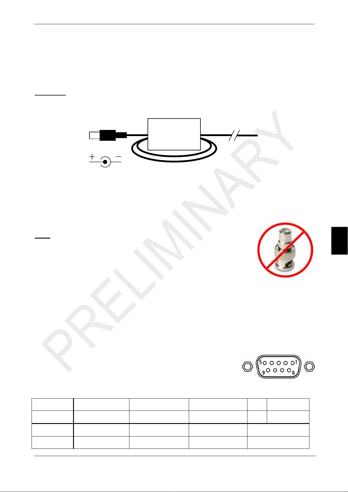
1.5 Recommendations for Installation ................................................................................................. 6
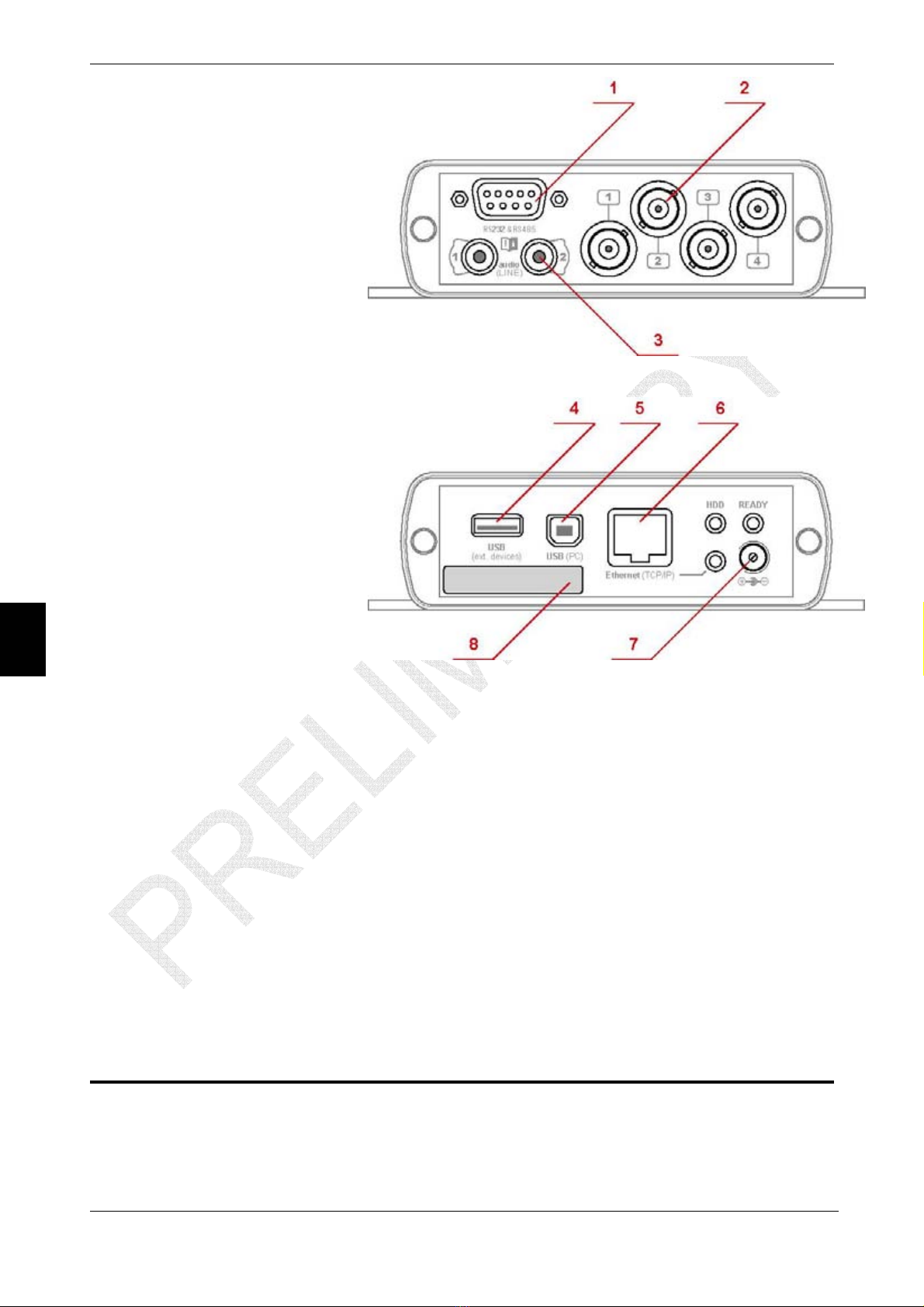
1.6 Connectors Description................................................................................................................... 6
1.7 LED Display....................................................................................................................................... 7
2. First Connection (via Ethernet) .................................................................................7
2.1 Network Settings (crossover cable) ............................................................................................... 8
2.2 Setting the Viewing Software.......................................................................................................... 8
3. Working with DVR ......................................................................................................8
3.1 Viewing Mode.................................................................................................................................... 9
3.2 Archive Mode.................................................................................................................................... 9
3.2.1 Control............................................................................................................................................ 9
3.2.2 Record.......................................................................................................................................... 10
3.2.3 Activity .......................................................................................................................................... 10
3.2.4 Save ............................................................................................................................................. 11
3.2.5 Jump to......................................................................................................................................... 11
3.2.6 Events .......................................................................................................................................... 11
3.3 Settings Mode................................................................................................................................. 12
3.3.1 Video ............................................................................................................................................ 12
3.3.2 Audio ............................................................................................................................................ 13
3.3.3 Timer ............................................................................................................................................ 14
3.3.4 COM port...................................................................................................................................... 15
3.3.5 Disk .............................................................................................................................................. 16
3.3.6 Software ....................................................................................................................................... 17
3.3.7 Time & Date ................................................................................................................................. 18
3.3.8 Network ........................................................................................................................................ 19
3.3.9 Passwords.................................................................................................................................... 21

Rev. 02 / September 2005
4. Client Software .........................................................................................................21
4.1 Displayed Video Settings............................................................................................................... 22
4.2 Properties Window......................................................................................................................... 23
5. Operation via USB....................................................................................................23
5.1 First Steps....................................................................................................................................... 23
5.2 Troubleshooting ............................................................................................................................. 25
6. Operation via WiFi-USB ...........................................................................................25
6.1 Ad-Hoc Mode................................................................................................................................... 25
6.2 Infrastructure Mode........................................................................................................................ 26
7. Optional Accessories / Supported Equipment.......................................................26
7.1 External Alarm Box (ALARM81-RS).............................................................................................. 26
7.2 External GPS Receiver (GPS20CH-RS) ........................................................................................ 27
7.3 External WiFi-USB Adaptors......................................................................................................... 27
7.4 PTZ Speed Domes.......................................................................................................................... 29
7.5 Access Control / Registering Systems ........................................................................................ 31
8. General Notes...........................................................................................................31
8.1 Operation Conditions..................................................................................................................... 31
8.2 Warranty.......................................................................................................................................... 31
8.3 Declaration of Conformity (CE)..................................................................................................... 32
9. Technical Data..........................................................................................................32
9.1 Minimum System Requirements (PC Workstation)..................................................................... 32
9.2 DiREX-Pro Specification (DVR)..................................................................................................... 32
10.Frequent Asked Question (FAQs)...........................................................................33
Great care was taken in preparing this manual. Constant product development may mean that some
information is not entirely up-to-date.
The information in this is subject to change without notice. bwa technology GmbH shall not be liable for
technical or editorial errors or omissions contained herein; not for incidental or consequential damages
resulting from the performance or use of this material. This document contains information protected by
copyright. No part of this document may be photocopied or reproduced in any form without prior written
consent from bwa technology GmbH.

© 2005 bwa technology gmbh
4
1. Introduction
Important legal Note:
Video and audio observation (CCTV) may be subject of legal regulation in your region.
Therefore please follow your local laws!
In case of malpractice, no responsibility can be assumed by the manufacturer
of this equipment.
Copyrights
•“bwa” and “DiREX-Pro” are trademarks of bwa technology GmbH, Germany.
•“Windows” is a trademark or registered trademark of Microsoft Corporation.
•“Macintosh” is a registered trademark of Apple Corporation.
•“Panasonic” is a registered trademark of Matsushita Electric Industrial Co., Ltd.
•All other corporate names and trademarks mentioned in this manual are the property
of their respective owners.
1.1 Safety Warning
Follow these safeguards and use the equipment properly to prevent injury, death or
material damage.
•To prevent fire, overheating, chemical leakage and explosion, follow the safeguards
below:
·Do not use any power sources or accessories not specified in this booklet.
·Do not insert any foreign metallic objects into the electrical contacts of the DVR,
accessories, connecting cables etc.
•Do not leave any cords near a heat source. This can deform the cord or melt the
insulation, causing fire or electrical shock.
•Do not use the equipment near flammable gas. This is to prevent an explosion or fire.
•If you drop the equipment and the casing breaks open to expose the internal parts, do
not touch the internal parts due to the risk of electrical shock.
•Do not disassemble or modify the equipment. High-voltage internal parts can cause
electrical shock.
•Do not store the equipment in dusty or humid places. This is to prevent fire and/or
electrical shock.
•To prevent fire and electrical shock, follow the safeguards below:
·Always insert the power plug all the way in.
·Do not handle a power plug with wet hands.
·When unplugging a power plug, grasp and pull the plug instead of the cord.
·Do not scratch, cut, or excessively bend the cord or put heavy objects on it. Also,
do not twist or knot the cord.
·Do not connect too many power plugs to the same power outlet.
·Do not use a cord with damaged insulation.
•Occasionally unplug the power plug and use a dry cloth to clean off the dust around
the power outlet. In dusty, humid, or oily surroundings, the dust on the power outlet
may become moist and short-circuit the outlet to cause a fire.

1. Introduction
© 2005 bwa technology gmbh
5
1.2 General Information
DiREX-Pro DVRs allow continuous recording of video information, entered via four video
cameras (or other analogue video sources, BNC connectors), as well audio, entered from
two sources (RCA connectors, LINE signal level). If fewer video or audio sources are
used, all idle inputs must be switched off manually and the BNC video jacks protected
with the caps supplied. Video (and Audio) information can be stored:
•continuously (if ring memory mode activated);
•or controlled by:
·motion (on the same or neighbouring channel);
·sound (adjustable sensitivity, with or without audio recording);
·external alarm (optional accessory required).
In this case both:
·10 seconds pre-alarm (located in RAM buffer)
·and user-adjustable shut-off time
are provided for each AV channel.
Note: all analogue (video and audio) inputs are electrically insulated.
Additionally, the DVR uses an internal battery-buffered clock to store current Time/Date
stamp. System- or channel-specific events will also be registered. Depending on the
model, all information is stored on the internal hard drive (HDD) or on the Flash Solid
State Drive (storage without movable parts).
A PC client is needed to configure and view live, or to download pre-recorded video/audio
information. Connection to a PC is made via 10/100 Mbit network or USB interface. The
DVR uses external 12VDC power supply (supplied).
All necessary software and firmware in a choice of languages, as well additional drivers
for optional external extensions can be found on the CD supplied and are also available
for download on bwa’s web site:
http://www.bwatech.com
1.3 List of Contents
There are following are included in each package:
•DiREX-Pro DVR;
•Carrying case;
•Power supplier FW7400/12 (IN: 100…240VAC / OUT:12VDC/1A);
•Wall mounting plate for FW7400/12;
•Country-specific power cable (available: continental Europe, UK, USA, Australia);
•Ethernet crossover cable;
•USB cable;
•D-Sub 9pin mini gender changer (female-to-male);
•3x BNC protection caps for video inputs when not in use;
•CD with current drivers, software, firmware (e.g. for changing user interface lan-
guage: English, German, French etc.) and additional documentation.
In addition, DiREX-Pro.A30 and DiREX-Pro.F16 DVRs come with:
•Ferrite snap-bead power filter.

DiREX-Pro User Manual (v. 0.1950)
1.4 DiREX-Pro.A30 and DiREX-Pro.F16
Thanks to an extended operating temperature range, the permitted ambient temperature
gradient and higher vibration stability, DiREX-Pro.A30 and DiREX-Pro.F16 are suitable
for using in vehicles (12VDC only) and for outdoor applications. In such cases, an
additional waterproof enclosure, different power supply with corresponding operation
temperature range and 12VDC/1.5A (min.) output is necessary.
Attention: for in-vehicle use, please wind the 12VDC power cord 3 times through the
power filter (supplied), as close as possible to DVR, as shown below:
1.5 Recommendations for Installation
All cameras have to provide the same signal level at the plug-in jack. Note that when
choosing a camera, a better signal/noise ratio (recommended: >46dB) is more important
than higher resolution.
© 2005 bwa technology gmbh
Note: avoid using RCA-to-BNC adaptors: when plugging in a
video jack, first connect a signal ground and THEN a
signal lead.
6
Audio sources have to provide the same signal level (LINE-IN) as
well.
1.6 Connectors Description
The enclosure of DiREX-Pro DVR can be regarded at two logical parts:
•the “application part” (front) – for using with external video/audio/data sources and
•the “communication part” (back) – for status indication, connection to computer
and power source (e.g. future power-via-Ethernet adapter as well).
Application part:
1. D-Sub 9pin connector (female) provides connection of
RS485 devices (IR / PTZ control) and RS232 devices
(alarm inputs/outputs, GPS receiver etc.).
Description of the DiREX-Pro RS232 / RS485 connector layout:
Pin no. 1 2 3 4 5
Description RS485#1 R(B) RS232#2 (RxD) RS232#2 (TxD) n/c GND
Pin no. 6 7 8 9
Description RS485#1 R(A) RS232#0 (TxD) RS232#0 (RxD) +9…16V DC-out

1. Introduction
2. Analogue (depending on
model: PAL or NTSC)
video signals (approx.
1Vcc) should be con-
nected to BNC jacks.
3. Analogue audio signals
(approx. 1Vcc) should be
connected to RCA jacks.
Communication part:
© 2005 bwa technology gmbh
7
storage devices (planned
5. interface is used
6. Mbit
7. y
8. dition, there is a
4. USB-A interface is used
for control external com-
munication (e.g. WiFi) or
by future firmware up-
dates).
USB-B
for connection to PC
(and/or to Ethernet).
Ethernet 10/100
interface provide TCP/IP
connection to the DVR.
12VDC power suppl
should be connected to
the power jack with “+”
on 2.1mm internal con-
tact.
In ad
type plate at recorder’s
communication site which containing the following information:
oProduct description (e.g. DiREX-Pro.40, DiREX-Pro.A30 etc.);
oSupported video system (PAL or NTSC);
oMAC address (with corresponding bar code);
oDevice serial number;
oHardware revision number.
1.7 LED Display
1. Steady blinking of the green LED (“READY”) means that recording is in process.
The frequency is proportional to the recording frame rate and relates to each key
frame.
2. Blinking of yellow LED (“Ethernet”) signifies communication via Ethernet network.
3. Blinking of red LED (“HDD”) signifies data access to internal storage.
2. First Connection (via Ethernet)
DiREX-Pro DVR can be connected to a local Ethernet network as well direct to PC via
crossover cable (supplied).
It is recommended to use a 10/100 Mbit network connection and to set the graphic card
to 32 bits video depth. To this aim, please use the “properties” desktop pop-up window
(or control panels).

DiREX-Pro User Manual (v. 0.1950)
2.1 Network Settings (crossover cable)
After connection to PC the network protocol TCP/IP has to be configured manually. The
settings required are:
•the static IP address: 10.0.0.1
•subnet mask: 255.255.255.0
2.2 Setting the Viewing Software
The latest version of viewing software and device
firmware can be found in the download area of
bwa’s web site:
http://www.bwatech.com
To display the audio/video stream transmitted
from DiREX-Pro, it is necessary to install the
following on the client PC:
© 2005 bwa technology gmbh
•DiREXPro-DLL;
•Microsoft DirectX 8.1 or above;
•change Internet Explorer settings “Check for
newer versions of stored pages” (“Tools” >
“Internet Options…” > “Temporary Internet files” >
“Settings”) to: ”Every visit to the page”
For trouble-free use of your DVR, please ascertain that
the PC workstation used offers sufficient performance. In
Windows Task Manager (key combination: “Alt” + “Ctrl” +
“Del”), the displayed value of CPU Usage level (during
video broadcast with maximum resolution – see next
section) must always be under 50%.
8
3. Working with DVR
The DVR’s default
IP address is:
http://10.0.0.2
Main menu:
“View” mode
displays live video
connected to the
video inputs. The
frame rate
(/second) depends
on the quality of
the connection
channel, therefore
it can be slower
than the real
recording speed;

3. Working with DVR
“Archive” mode provides access to information already recorded in the DVR;
“Setting” mode is used for device configuration and changing of audio, video settings etc.
3.1 Viewing Mode
The following items are displayed only if the corresponding dome protocol is pre-selected.
See section 3.3.4 for dome/PTZ/IR settings.
“Control” block allows selection of camera, PTZ unit or IR lighting,
witch should be adjusted.
“Positions” block allows selection of one of 9 pre-programmed
positions and camera settings (speed dome control). If held for more
than 3 seconds, or by right-clicking the mouse, the current position will
be saved and the same confirmed by the button changing colour and
(depending on dome firmware) the “MEMORY” message in the video
area.
“Platform” block allows the current alignment of PTZ platform of the selected camera to
be changed. The position can be stored by holding the corresponding settings button.
“Lighting” block – switches the lighting of selected camera on or off.
© 2005 bwa technology gmbh
Dome and IR control are
accomplished via the RS485
interface. The corresponding
camera protocol should be
prior-selected in COM port
setting window.
9
3.2 Archive Mode
This mode allows playback of
previously recorded informa-
tion from a video archive on
the internal hard drive.
3.2.1 Control
“Control” block enables
playback control in archive
mode:
•Stop;
•Playback with normal speed;
•Playback of two frames only (symbol “playback” with “1”);
•Fast backwards (key frames only);
•Fast playback (key frames only);
•Jump to previous key frame;
•Jump to next key frame;
•x1…x4 – playback speed multiplayer.

DiREX-Pro User Manual (v. 0.1950)
3.2.2 Record
“Recording” block – by pushing “■” or “REC” button, is it possible to
stop or continue video recording (if the button is red, recording is in
process, if grey, recording has stopped). This option is needed for
freeing-up resources to speed up playback or download data from the
DVR. When “Extension of HDD’s Durability” mode is activated (i.e.
before writing video stream onto the HDD, the volatile memory buffer is used), this buffer
will be automatically stored on the HDD in case recording is interrupted. Once recording
is disabled (using the “■” button), it will continue automatically not more than 30 minutes
later.
Note: disabling recording after disables the live video transmission.
3.2.3 Activity
“Activity” item initialises an activity-graph (in new pop-up window) of
audio and video channels. The scroll bars “Time” and “Scale”
approximately select the required archive segment – move the mouse
on the corresponding part of the graph and, after left-clicking the
mouse at the selected point, the playback point will move to the corresponding time.
Windows “Activity” contains the properties of the selected time frame. The colour bars
signify the following:
•Grey colour – activity level;
© 2005 bwa technology gmbh
•Dark grey – motion or sound sensor (detection) activity;
•Green – alarm sensor (contacts) activity;
•Red – system events. 10
The “Begin” item
contains the first
time/date and
“End” the last
time/date of the
selected frame.
Clicking the
“Select fragment”
button gives the
segment selection
for downloading
from the DVR. The
first left-click of the
mouse selects the
beginning
(corresponding
time/date shown in
“Begin” item), and
the second click the end point (corresponding time/date shown in “End” item). Clicking on
“Save fragment” brings up standard MS Windows file saving procedure and the selected
section will be downloaded.
The left/right scroll bar “Time” buttons enable scrolling the activity chart: one arrow –
step-by-step, double arrows – to the next half screen.
After clicking the “30 min” button, the time axis displays a 30 minutes scale.

3. Working with DVR
System events (shown in red) include:
•device switched on/off – “DEVICE IS SWITCHED ON”;
•recording switched on/off – “RECORDING ACTIVATED”
/ “RECORDING DEACTIVATED”;
•video signal detection/lost – “VIDEO DETECTED AT CAMERA NO.”
/ “VIDEO LOST AT CAMERA NO.”;
•changing device configuration – “DEVICE SETTINGS CHANGED”;
•system conditional reboot – “0012”.
An event on a video channel – video sensor activation – is shown by the message
“motion” and an event counter; an event on a audio channel – sound detection – is
shown by the message “sound” and an event counter. The counter value begins at “0”
and will reset each 24 hours.
© 2005 bwa technology gmbh
11
3.2.4 Save
“Save” is used to invoke the save dialogue (in new pop-
up windows), needed for download information from
DVR to PC. The first “Save segment” window contains
the time and date of the first recording of 1 hour’s
duration. After clicking the “Save” button, the standard
MS Windows “Save as…” procedure continues. The
start year, month, date and time will be added in the following format to the file name
entered: name_YYYYMMDD_TTMM.msn
Note: the exact beginning and ending points of the saved part will be rounded to the
next video key frames.
*.MSN files can be viewed and (if necessary) split in smaller parts or exported into *.AVI
format using playback software MSN-Player, available on the CD supplied or on the
manufacturer’s web site.
3.2.5 Jump to
The “Go to” block is used to enter the time and date of the start of
playback. After entering the time and date in the corresponding fields,
click the “Go” button for the DVR to go to playback mode starting from
the time/date entered.
After clocks change backwards (e.g. summer to winter time), the time
search will select the earlier time.
Note: to ensure proper operation of the time/date search, the MS
Internet Explorer must be configured to “update temporary
internet files by Every visit to the page”.
3.2.6 Events
The “Events” block is used for event search by selected attributes.
The pop-up item allows the selection of channel or global event type.
•Buttons “>>” and “<<” allow fast selection of the next or previous event. By choos-
ing the pop-up item “system events”, event-controlled video playback will begin.

DiREX-Pro User Manual (v. 0.1950)
•The button “P>” means playback video until next global event occurs.
•Buttons “R<” & “E>” are used for fast video playback up to previous or next event.
3.3 Settings Mode
This mode allows the changing of DVR operation modes. To prevent unauthorized device
reconfiguration, it is recommended to enable password protection of this mode.
3.3.1 Video
This page configures the settings of video signal processing.
© 2005 bwa technology gmbh
The “Common
settings” block
sets the general
parameters for
all video
channels, such
as DVR name,
resolution,
colour standard,
brightness,
contrast,
saturation. The
“system
performance”
item gives the
choice of better
performance
(i.e. more
frames per
seconds) of
better quality
(i.e. better video
sharpness).
12
Note: your DVR support either PAL or NTSC video system. Please refer to the
descriptive plate located on device connection panel – see section 1.6.
“Channel 1”… “Channel 4” blocks set the parameters of each video channel separately.
Definition of each item:
•“name” – text displayed in the respective video window;
•The “on” flag activates each video channel
(it’s important to deactivate idle video channels!);
•“quality” – video quality 2 or 3
(3 – standard quality and low data stream, 2 – best quality and higher data rate);
•“FPS reduction” – divider of maximum frame rate for this channel: 1…12
(1 means - record all frames, 2: record each second frame, 3: each 3rd frame etc.);
•“video sensor” this flag activates the registration of motion detection on full frame
area ( the “motion” message with corresponding number will be displayed);
•“threshold value” denotes the sensitivity of video sensor,
100% means that the next video frame is complete different to the previous;

3. Working with DVR
•“sensor-activated recording only” this flag signifies recording if video or alarm
sensors are activated (thanks to pre-alarm functionality, the preceding 10 seconds
will also be recorded);
Note: if video recording is idle for a motion or alarm event, the red “X”
will be displayed in the left-hand corner at bottom of the corre-
sponding video channel. See section 4.1 for other video settings
displayed.
•“shut-off time”: how long recording continues after deactivation
of the video or alarm sensors;
•“initiate common event” flag: this event can be used on other
channels for video or audio recording;
•“start recording by common event”: starts recording as soon a
a common event is registered (with continuous, 10-seconds pre-
recording);
s
•The name of the video event can be defined in the “event name” field;
•“noise reduction” allows reduction of video noise and thereby reduces the data
stream level which is particularly useful when recording at night;
To store information in the device, press the “Apply” button.
The following example shows how to configure the DVR for recording from 2 cameras
with:
© 2005 bwa technology gmbh
1. channel: continuous recording;
2. channel: recording only in case of movement detection on channel #1.
13
on
video
sensor
sensor-
activated
recording only shut-off
time initiate
common event start record by
common event
Ch. #1 yes yes no required
value Yes no
Ch. #2 yes no yes 5 sec No yes
Ch. #3 no
Ch. #4 no
3.3.2 Audio
This page configures the
settings of audio
channels.
Blocks “Channel 1” and
“Channel 2” contain the
properties of each
channel separately.
Definition of each item:
•“name” – the label
of the respective
audio stream;
•The “on” flag

DiREX-Pro User Manual (v. 0.1950)
activates recording on the respective audio channel
(it is important to deactivate idle audio channels!);
•“sampling rate” pop-up selects audio sampling rate – a higher rate means better
audio quality, but proportionally higher data rate and more storage space required;
•“stereo” flag enables stereo mode, i.e. audio signals will be taken from both inputs
and put onto one logical channel without the possibility to split it later;
•“audio sensor” flag activates the registration of sound detection
(a “sound” message with corresponding number will be displayed);
•“threshold value” – sensitivity of the audio sensor;
•“sensor-activated recording” flag: recording activated by sound only
(thanks to pre-alarm functionality, the preceding 10 seconds will also be recorded);
•“shut-off time” – how long recording continues after deactivation of the audio
sensors;
•“initiate common event” flag: this event can be used on other channels for video
or audio recording;
•“start recording by common event”– start recording as soon as a common event
is registered (with continuous 10-seconds pre-alarm recording);
•The name of the audio event can be defined in the “event name” field;
Note:
if both “audio sensor” and “initiate common event” flags are activated, this function can
be used (see example in previous section) for control of video recording without local
audio recording even if the “on” flag is not marked and, therefore, does not reduce the
total video recording capacity.
© 2005 bwa technology gmbh
To store information in the device, press the “Apply” button. 14
3.3.3 Timer
This page sets the video recording or
real time viewing deactivation time
separately for each day of the week.
Note:
if video recording is deactivated, the
video server can be deactivated as
well and thus it is not possible to view
live video stream(s). This feature can
be used to provide privacy at
predefined time frames – e.g. to
prevent a violation of employees’
privacy.
If the related time/date position is not
checked, the video section (selectable:
viewing and recording, or real time
viewing only, or local recording only) is
completely shut down during this time
period.
To store information in the device,
press the “Apply” button.

3. Working with DVR
3.3.4 COM port
This page configures devices connected to the DVR via RS232 and RS485 interfaces.
For description of the connector layout, please refer to section 1.6 of this manual.
“Monitoring of Alarm-Inputs
and Control of Alarm-Output”
activates the alarm output (relay
contacts) if a common event
takes place or activates the
registration of alarm detection.
This feature requires the
optional accessory ALARM81-
RS.
“Relay releasing during
common event” enables the control of external equipment by motion or sound detection.
The release time depends on the shut-off time selected in video or audio channel, witch
“initiate(s) common event”.
© 2005 bwa technology gmbh
“Camera 1”…”Camera 4” blocks enable the activation/deactivation of corresponding
pairs of alarm sensors. If the alarm sensors (two inputs for each video channel) are
activated, a message showing released/unreleased count for each input will be displayed
on the respective video channel. The pop-ups configure each input for activation
according to “by opening” or “by closing”. For contact-controlled video recording, the
“sensor-activated recording only” in the respective video channel (“Settings” > “Video”)
should be selected.
15
The following example shows how to configure the DVR for recording from two cameras
with:
1. channel: recording only if alarm input #1 activated + “value #1” seconds;
2. channel: continuous recording, if movement detected, the alarm output
is activated during movement and additionally “value #2” seconds.
on
video
sensor
sensor-
activated
recording only shut-off
time initiate
common event start record by
common event
Ch. #1 yes no yes value #1 No no
Ch. #2 yes Yes no value #2 Yes no
Ch. #3 no
Ch. #4 no
Yes
Relay releasing during common event (ch.2 movement + “value #2” sec)
Alrm.1 yes
Alrm.2 no
“Dome / PTZ Camera Settings”. This block configures the RS485 PTZ settings.
Dome/PTZ pop-ups:
•“camera type” set the related PTZ protocol. If no cameras are connected, please
select “no camera” – in this case, camera control buttons will not be displayed in the
“View” windows;
•“address” – hexadecimal camera ID;
•“speed” – one of 8 pre-selected dome rotation speed;

DiREX-Pro User Manual (v. 0.1950)
•“drive positions” selects presets (first 9)
that have to be driven automatically.
This feature depends on the selected
protocol and is presently supported by
Pelco D and Panasonic only;
•“pause (sec.)” – duration at given
position;
•“hold on|off” button acti-
vates/deactivates the image hold func-
tion. If activated, the camera will freeze
the video picture while moving to the
next position, thus reducing storage
space used.
To store information in the device, press the “Apply” button.
3.3.5 Disk
© 2005 bwa technology gmbh
The “Drive
Information” block
contains information
about HDD model,
serial number,
microcode version,
current drive
temperature and
maximum tempera-
ture reached after
the last firmware
update (see section
3.3.6), total capacity, allocated space, free space and the time of first and last recording.
16
Allowed drive temperature (see section 8.1 for ambient temperature range):
DVR model DiREX-Pro.40/.120 DiREX-Pro.A30 DiREX-Pro.F16
Temperature
Range +5…+65 °C -20…+85 °C -10…+70 °C
“Circular (FIFO) Recording” enables or disables ring recording. To store the mode
selected, click on the “Save” button. If this mode is enabled, about 10% of HDD storage
capacity will be reserved.
By clicking on the “Format” button, the internal HDD will be reformatted – meaning all
recorded information will be erased. Formatting takes up to 10 minutes. In rare cases,
the DVR will have to be restarted manually by reconnecting the plug-in. After formatting,
click the “continue” button and the device will continue operation.
“Extension of HDD’s Durability”. This block considerably increases the estimated life
time of the internal hard drive. In this mode, the audio/video stream will be first stored in a
volatile RAM buffer and, only when the buffer becomes full, its contents moved to the
HDD. Thus the HDD is accessed once every few hours or so and, therefore, unplugging
the device would lead to unsaved parts of video (still located in RAM) being lost. If using
uninterrupted power supply, this mode provides optimum DVR operation when using the

3. Working with DVR
device in an environment with 24 hours movement (e.g. railway station, large fuelling
station shop etc.).
Note: If this mode is deactivated (default setting) the audio/video information will be
stored on the HDD approx. every 6 seconds.
When viewing the video archive, only information already recorded on the HDD is
accessible. AV data can be moved from the RAM buffer to the HDD not only when the
buffer is full, but also by clicking the “■” button in the “Archive” (refer section 3.2.2)
screen and also by changing any setting.
Activation of “internal drive(s) on standby if data rate low” (the “Save” button has to be
clicked) enables recording in the RAM buffer.
3.3.6 Software
For operation with external devices and for extending functionality, additional software
packages should be loaded into the DVR. Information on installed software packages is
displayed in the “Installed Packages” block. The following devices / services are
supported without additional software modules:
•ALARM81-RS (alarm in/outs: 8 contact inputs / 1 relay output) external box, con-
nected to RS232#2 interface;
•WiFi-USB adapter (PRISM-II.x chipset, e.g. D-Link DWL-122/A1) provides WLAN
Ad-Hoc and Infrastructure modes;
© 2005 bwa technology gmbh
Additional software modules (which can be removed later) support:
•GPS NMEA receiver (e.g. GPS20CH-RS accessory) connected via RS232#2
/4800bps;
17
•FTP server provides additional access to the contents of the DVR. For access rights,
please refer “readme.txt” attached to this software module.
Attention: during installation of the GPS package (or other devices connected to
RS232#2), ALARM81-RS settings must be deactivated!
The “Identifier” item
contains a short descrip-
tion of the operation
system or the driver.
The “Detailed descrip-
tion” item contains an
extended package
description, revision
number and, if applicable,
series number and MAC
address.
The “Settings” block is for
managing the internal
DVR settings.
The button “Default
setting” restores factory
defaults.

DiREX-Pro User Manual (v. 0.1950)
Note: to provide connectivity to the DVR while restoring settings, all network settings
remain the same.
The “Save settings” button uploads the current DVR settings to a PC for restoring later.
If settings are changed manually, new settings file is downloaded, or factory defaults are
restored, the “Previous settings” button restores (from the internal FLASH memory) a
backup of last settings.
The “Reboot” button enables device software to restart the DVR and can be useful for
“safety” shutdown – just unplug the power supply approx. 1-2 seconds after restarting.
Additional software packages, settings files and new firmware releases or firmware
supported in other languages (e.g. German, French, etc.) can be downloaded in the
“Software” block.
Attention:
It is recommended to download software to the DVR via a 100Mbit Ethernet
connection only. Please do not use USB or WLAN connections for downloading!
After the firmware download, about 30 seconds are needed to reprogram the
internal FLASH memory. During this period, please do not unplug the DVR, refrain
from any activities such as viewing, setting, etc. using the DVR, do not interrupt
the network connection and wait until “LINK” (green) LED blinks regularly.
© 2005 bwa technology gmbh
Failure to observe the above may damage the device, which in turn, may mean
having to send it to the manufacturer or his certified representative for repair at
extra cost. 18
For more information about the latest software packages, new firmware releases and
enquiries regarding customised software modules (e.g. for collecting data from POS
terminals), please visit the support section of bwa’s internet site:
http://www.bwatech.com/en/main/support.html
3.3.7 Time & Date
In the block “Time / Date” the “date” item is used for manually entering (from left to right)
the current:
•day, month and
year.
The “time” item is
used for manually
entering (from left to
right) the current:
•hour, minute
and seconds.
The “time zone” sets the correct time zone and is useful for external time synchronisation
– timeserver or RS232 signal (GPS signal, POS terminal etc. – see sections 7.2 and 7.5).
The “Correction and Synchronisation” block contains items needed for the automatic
adjustment of the internal clock:
•“clock time adjustment (sec/day)” – speed internal clock up/down (+/-);

3. Working with DVR
•“synchronisation with external server” – name or IP address of external time
server;
•“use NTP protocol” – NTP (RFC.868), external proxy server must be disabled;
•“use RS232 data” – e.g. a time signal from GPS receiver, POS terminal or other
device connected to RS232#2 interface. An additional software package must be
installed – please refer the “Software” (3.3.6) section of this manual.
Attention: during installation of the GPS package (or other devices connected to
RS232#2), the ALARM81-RS settings must be deactivated!
By clicking the “Apply” button, the time/date entered will be send to the DVR to adjust the
internal clock.
3.3.8 Network
This item changes the device’s network settings and configures e-mail notification.
“Network Settings” contains standard network settings:
•“network name” defines the device name in the network;
•“domain” defines the name of the domain to which the device is connected;
•“IP address” sets the DVR IP address provided by the network system administrator;
•“DHCP” should be selected if a DHCP service (dynamic IP
address) is used in the local network. In this case, the IP
address and next four settings will be provided by the local
DHCP server;
© 2005 bwa technology gmbh
•“network mask” is used to enter the network mask;
•“default gateway” is used to enter the IP address of the
default gateway;
19 •“DNS server 1” IP address of the primary DNS server;
•“DNS server 2” IP address of the secondary DNS server;
•“WiFi network address” DVR’s IP address in the WiFi
network when using an external WiFi-USB adapter. WiFi
connection enables wireless to the DVR wireless. For
information on supportable WiFi-USB sticks, please refer
to section 7.3 of this manual;
•“DHCP” should be selected if a DHCP service is used in
the WiFi network (useful for Infrastructure mode);
•“network mask” network mask for WiFi connection;
•“WiFi mode” – Ad-Hoc (direct computer-to-computer
connection) or Infrastructure (automatic connection to
local network via Access Point) mode can be selected;
•“WiFi SSID” the name given for Ad-Hoc or the name of
the Access Point for Infrastructure connection;
•“telnet protocol” additionally enables a telnet protocol for connecting to the DVR.
This protocol is useful for device administration. When connecting to the device for the
first time, please enter user name root without any password.
Attention: if the telnet protocol is enabled, full access to the device is possible
without any additional password protection!
•“use dynamic DNS” enables the use of an external dynamic DNS service. Dy-
namic DNS can be useful for access to the recorder from the Internet in case no
permanent connection with a static IP address is available;

DiREX-Pro User Manual (v. 0.1950)
•“dyn. DNS server” selects the address of the dynamic DNS server;
•“host” device name within the DNS service;
•“Login” and “Password” – corresponding login and password within the DNS
service.
Note: it is recommended to enable dynamic DNS service not from the DVR, but from
a DSL/ISDN router connected between the local network and the Internet.
Attention: During unqualified changing of the network settings, connection to the
DVR will be lost! In this case it is still possible to access to the device
via USB connection or by using the service shop.
In case of physical disconnection from the recorder, please wait until the device is
reconnected and, if necessary, use the “connect”/”disconnect” or “repair” items in the
Windows network settings.
© 2005 bwa technology gmbh
“Notification via e-mail” contains
the settings needed for sending, in
preset intervals, status information
about the DVR in case of activation
of the motion or sound sensors,
whether by system event or timer-
controlled. To send e-mails, the
recorder uses the SMTP server of
the local network. To use this
service, the IP address of the SMTP
server and corresponding login /
password for access to the server
(if necessary) have to be defined.
The remaining items are:
20
•“notify to following e-mail”:
the target e-mail address;
•“photo”: if selected, the
camera stills at the moment
of notification will be additi
ally attached to the e-mail
“own
on-
;
•e-mail address”: this
address will be used as the sender’s address;
•“by motion or sound”: this message will created in case of activation of motion or
sound detectors on any video or audio channel;
•“by system event”: this message will be generated by any system event, e.g.:
video signal lost, power interrupted, etc.;
•“timer-controlled”: this message will generated in accordance with the selected
time and date of the week in the right-hand part of the same screen;
•“by alarm (contact)”: this message will created in case of activation of any alarm
input – see section 3.3.4 for details.
Note: timer-controlled notification and Timer settings (“Settings > Timer” item) have a
completely different function!
For erasing all unsent messages the internal drive should be formatted (s. section 3.3.5).
By clicking at “Apply” button, the setting entered will be stored in the DVR.
This manual suits for next models
3
Table of contents