BXB Electronics WMP-2100 User manual

0
W
WM
MP
P-
-2
21
10
00
0
D
Di
ig
gi
it
ta
al
l
P
PA
A
s
sy
ys
st
te
em
m
I
In
ns
st
ta
al
ll
la
at
ti
io
on
n
G
Gu
ui
id
de
e
V
V
Ve
e
er
r
rs
s
si
iio
o
on
n
n:
:
:
1
1
1.
.
.2
2
2
D
D
Da
a
at
t
te
e
e:
:
:
A
A
Au
u
ug
g
gu
u
us
s
st
t
t
1
1
16
6
6,
,
,
2
2
20
0
01
1
11
1
1

1
Table of Contents
Safety Instructions.......................................................................................................................................2
System Installation Instructions......................................................................................................................4
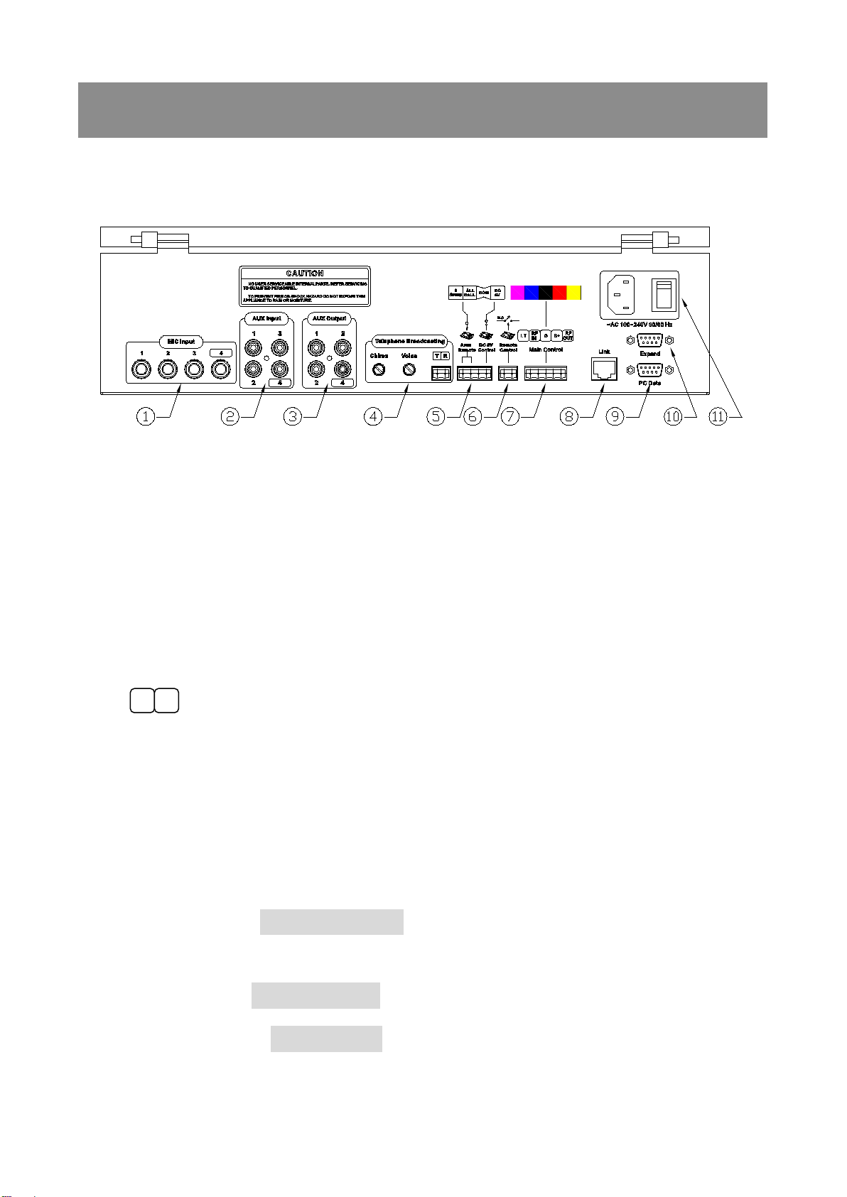
1. Rear Panel Function................................................................................................................................4
I. Main control cable and WMP-2100 configuration................................................................................. 6
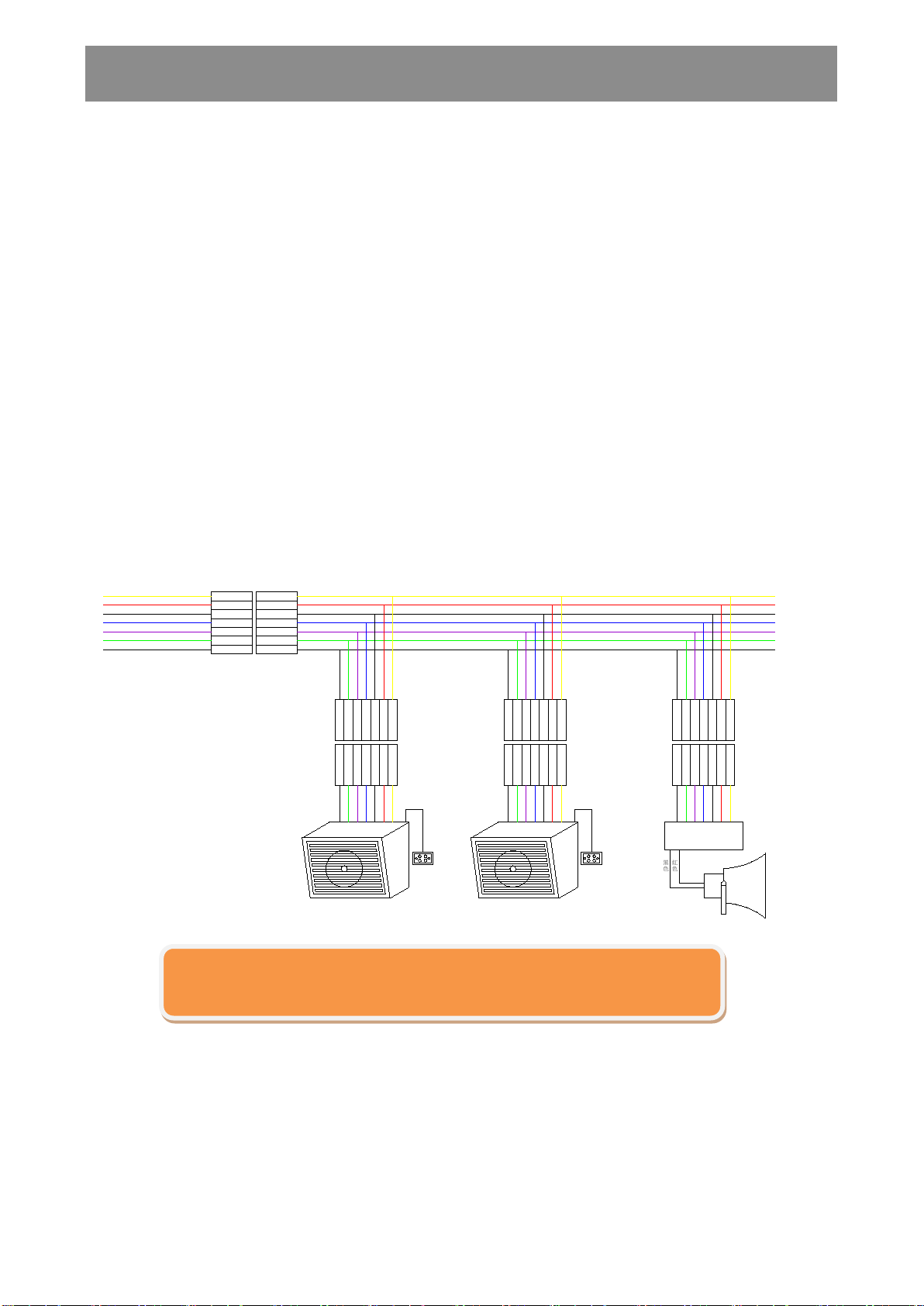
II. Connection between Main Cable and Remote Decoder........................................................................8
1. Remote Decoder (WMP-60) is built in BXB speakers:.............................................................. 8
2. Remote Decoder (WMP-60) is attached to the outside. .............................................................. 9
3. Remote Decoder (WMP-60) is attached to the outside of BXB amplifier teaching speaker... 10
4. WMP-60 Remote Decoder is used with BXB WS-335T vibrating buzzer................................. 10
5. Positions and setting of broadcast DIP switches........................................................................ 11
a. WMP-60 DIP switch setting:............................................................................................................. 12
b. WMP-60: 200 zones DIP switch chart ............................................................................................. 13
III. Linked control for two main console(s) (WMP-2100) ...................................................................... 14
IV. Connection for extension control device (WMP-2100A) .................................................................. 15
V. Connection for Graphical Control Software ........................................................................................ 16
VI. Connection for Telephone broadcasting system ............................................................................... 17
VII. External activated port and installation........................................................................................... 18
VIII. AUX Input Description & Application .............................................................................................. 19
1. MIC Input:................................................................................................................................... 19
2. External Aux input:.................................................................................................................... 19
3. External Aux output:.................................................................................................................. 19
IX. Inspection for wire configuration ...................................................................................................... 20
X. System Structure................................................................................................................................... 22
Before installation, please read this guide completely and keep it for your reference.

2
Safety Instructions
1. Please read and observe these instructions before installing and using the
apparatus.
2. Use only accessories specified by the manufacturer. The manufacturer is not
liable for damage caused by the use of non-specified accessories.
3. Install the apparatus and its accessories carefully. Strike and fierce shaking may
damage the apparatus.
4. Make sure the power cord is fixed properly.
5. Do not overload wall outlets and extension cords as this can result in a risk of fire
or short circuit.
6. To reduce the risk of damage from lightning strikes, it is important that all electric
cables should be bonded to the same grounding point.
7. Do not block any ventilation openings to prevent overheating and malfunction.
8. Do not expose the apparatus to rain or moisture.
Humidity may lead inside components to damage. Appropriate shelter is
necessary when placing it outside (Best working environment: Temperature 0°C
~ 40°C <32°F ~ 104°F>, humidity below 90%).
9. Please do not switch on and off the apparatus rapidly.
Rapid switch on and off the apparatus should be avoided all the time to prevent
inside sensitive electronic circuits from being damaged by surges.
10.Do not clean the apparatus and its accessories with chemical solvents. Use only a
clean, dry/dampish cloth.

3
11.Refer to maintenance technician when the apparatus has been damaged in any
way, such as:
A• power-supply cord or plug is damaged
B• liquid has been spilled in
C• has been exposed to rain or moisture
D• has been dropped
E• objects have fallen into the apparatus
F• does not operate normally
12.Note: When the printed circuit board is going through electric static treatment,
correct ESD safety precaution and grounding should be assured.
13.Note: Before connecting the apparatus to main AC, please select the supply
voltage in accordance with the wall voltage in your country to prevent damage.
Refer to Installation and Setting (Page 8) for selecting.
14.Warning: Do not disassemble or remodel the product, as these actions may lead
to electrical shock or damage. The guarantee on the product will become null if
the product is ever disassembled.
BXB and the logo are trademark or registered trademarks of BXB Electronics

www.BXB.tw
4
System Installation Instructions
1. Rear Panel Function
Functions:
○
1MIC-1~MIC-4: Microphone inputs (MIC1 has priority to broadcast)
○
2
AUX 1 should be reserved for telephone broadcasting
AUX1~AUX4: Aux inputs (for CD, tape cassette, radio and timer...)
○
3AUX OUTPUT:For external amplifiers or recorders
○
4
Connectors for telephone broadcast. System installers select an
available line from the PBX (private branch exchange) to connect.
After connected, you are able to broadcast via remote telephones.
Telephone broadcasting interface:
VOICE:Telephone broadcast volume knob
CHIME:Chime volume knob
○
5
Area Remote:ALL CALL+COM Enable ALL CALL, can be used with timer
clock
External trigger: To activate enforced control connectors
8 Group+COM Enable Group 8, can be used with timer clock
DC 5V Control:DC 5V+COM DC 5V output trigger connector. When
T
R

5
broadcasting, the connector will output DC
5V which can be applied to flash alarm
(BXB WS-335T)
○
6Remote Control:Dry contacts trigger connector. When broadcasting, the
connector becomes a short circuit; it can be used to
switch on other equipments as well.
○
7
RF OUT(Yellow):Signal output (from main console - decoders) connector
Main Control:Connector for main cable (WMP-7c)
B+ OUT(Red):DC-24V power connector for remote decoder (WMP-60)
G(Black):Common ground for remote decoder (WMP-60) control signal
RF IN(Blue):Signal input (from decoders - main console) connector
I.T(Purple):Connector for intercom signal
○
8Link:Connector for other main console(s)
○
9PC-Data:RS-232 interface for BXB graphical control software
○
10 EXPAND:Connector for extension control device (WMP-2100A)
○
11
AC 110V- 240V(FUSE 250V 8A):AC power socket and power switch (AC
90~240V 50/60Hz)

6
I. Main control cable and WMP-2100 configuration
Wires configuration of WMP-2100 features color management, there are
seven different control cables to transmit signals. Every colored cable is designed
for a unique function as shown below.
Color
Abbreviation
Function
Yellow
RF OUT
RF control signal cable: output signal to decoder
Red
B+ OUT
DC 24V on WMP-60 Decoder
Black
GND
RF IN
、
RF OUT
、
B+ OUT
、
INTERCOM same ground wire signal
cable
Blue
RF IN(KEY)
Return signal cable
For example: N.O
、
N.C and self-detect
Purple
INTERCOM
Intercom signal cable: need connect the signal wiper and
ground wire to control signal.
Green
COM
Power amplifier output AUX: No cathode or anode (No +/-
different)
White
100V
Power amplifier output AUX: No cathode or anode (No +/-
different)
GND
RF OUT
I.T
AMP COM
B+ DC 24V
RF OUT
POWER AMPLIFIER
POWER
AC
0FF
ON
AUTO FUSE
LEVEL
PL
PAB- 5400
AUTO FUSE
DC
AMP 100V
黃色
紅色
黑色
藍色
紫色
綠色
白色
GND
RF OUT
I.T
AMP COM
B+ DC 24V
RF OUT
AMP 100V
黃色
紅色
黑色
藍色
紫色
綠色
白色
WMP-2100
Fig . 1 Connection structure between WMP-2100 and WMP-7C

7
Warning:
1. For maintenance and installation, please refer to the chart above.
2. Every wire has its unique function so please make sure the wiring is correct
before turning on the unit. Otherwise, incorrect wiring might cause damage to
it. (Please refer to Quick Check Installations).
3. To prevent damage, please use wires attached with WMP 2100 only.

8
II. Connection between Main Cable and Remote Decoder
Connection instructions:
1st. Remote Decoder (WMP-60) is built inside BXB speakers (e.g.
WS-665AM/60D & WS-817ALM/60D; WS-665T/60D & WS-817TL/60D)
2nd. Remote Decoder (WMP-60) is attached to the outside.
1. Remote Decoder (WMP-60) is built in BXB speakers:
a. Main controller and speakers operate in parallel; easily connect wires by
colors according to the following chart.
b. 1 set of 7-colored quick connector is exposed to outside, connect them as
the way above.
Fig. 2 Connection instructions for WMP-7c and BXB speaker
(Build-in decoder)
GND
RF OUT
I.T
AMP COM
B+ DC 24V
RF OUT
AMP 100V
黃色
紅色
黑色
藍色
紫色
綠色
白色
GND
RF OUT
I.T
AMP COM
B+ DC 24V
RF OUT
AMP 100V
黃色
紅色
黑色
藍色
紫色
綠色
白色
10 0 V
COM
GND
RF OUT
I.T
AMP COM
B+ DC 24V
RF OUT
AMP 100V
黃色
紅色
黑色
藍色
紫色
綠色
白色
GND
RF OUT
I.T
AMP COM
B+ DC 24V
RF OUT
AMP 100V
黃色
紅色
黑色
藍色
紫色
綠色
白色
GND
RF OUT
I.T
AMP COM
B+ DC 24V
RF OUT
AMP 100V
黃色
紅色
黑色
藍色
紫色
綠色
白色
GND
RF OUT
I.T
AMP COM
B+ DC 24V
RF OUT
AMP 100V
黃色
紅色
黑色
藍色
紫色
綠色
白色
GND
RF OUT
I.T
AMP COM
B+ DC 24V
RF OUT
AMP 100V
黃色
紅色
黑色
藍色
紫色
綠色
白色
GND
RF OUT
I.T
AMP COM
B+ DC 24V
RF OUT
AMP 100V
黃色
紅色
黑色
藍色
紫色
綠色
白色
WMP-60 解碼器
黑色
紅色

9
Both red and black wire are connected to the speaker (output: 100V/COM), and
please neglect + or -. However, the speaker must be equipped with an
autotransformer; otherwise it might be damaged.
2. Remote Decoder (WMP-60) is attached to the outside.
※Note
The connection applies to any kind of high speakers. (Chart 3)
1. Parallel connection and color management is applied. Simply connect green to
green, white to white, blue to blue, red to red…etc.
2. Users are able to connect external speakers (ceiling speakers, horn
speakers…etc.), simply connect both red and black wires (Fig. 4) to the
speaker’s output autotransformer (there is no difference between cathode and
anode)
Fig. 3 external WMP-60

10
OUT B+ GIN COM
ID S.W
5
ON
2 3 41 7 86
G 100V
RF RF
MIC AUX
MIC Volume control
AUX Volume control
7C + 1 white PVC composite backbone
alarm speaker
3. Remote Decoder (WMP-60) is attached to the outside of BXB amplifier
teaching speaker.
Please refer to Fig. 4 for connection instructions.
4. WMP-60 Remote Decoder is used with BXB WS-335T vibrating buzzer
OUT B+ G IN COM
ID S.W
5
ON
2 3 41 7 86
G 100V
RF RF
alarm speaker
BXB WS-335T
- +
Call back trigger signal
GND
Access control security trigger signaltrigger signal
Lift call back signal contact
Fig. 4 Remote Decoder is used with BXB
amplifier teaching speaker
(WS-817AL, WS-665A)
Flash
Alarm
Fig 5. Remote Decoder (WMP-60) is used
with BXB flash alarm (WS-335T)

11
5. Positions and setting of broadcast DIP switches
Easily change broadcasting zone from the back of BXB speaker or on remote
decoder (WMP-60).
Where you can find it:
WMP-60 Remote Decoder
Amplifier Teaching Speakers:
WS-665Am/60D & WS-817ALM/60D
Box Speakers:
WS-665T/60D & WS-817TL/60D
BXB Speakers with built-in decoder (WMP-60D)

12
a.WMP-60 DIP switch setting:
Each switch on decoder represents one-bit binary value.
The values of all switches in the DIP package are
interpreted as one number.
Definition:
GP= Group code
(
To set Group 1~8, all ON is 7, all OFF is 8
)
Example 1
:Code 305
Group 3 and area 5
GP 03
DIP switch 6
、
7 are ON, 8 is OFF
CH 05
DIP switch 1
、
3 are ON, 2
、
4
、
5 are OFF
Example 2
:Code 812
Group 8 and area 12
GP 08
DIP switch 6
、
7
、
8 are OFF
CH 12 DIP switch 3、4 are ON, 1、2、5 are OFF

13
b. WMP-60: 200 zones DIP switch chart

14
III. Linked control for two main console(s) (WMP-2100)
※Note
1. WMP-2100 is able to connect other WMP-2100(s) (Fig.6 ) and work mutually.
2. A 9-core control cable and a 2-core audio source cable are essential.
3. Distance between two consoles should be less than 1km (0.6 mile). If the
length exceeds, please contact BXB Electronics for further assistance.
Fig. 6 connecting instructions for multiple WMP-2100s

15
IV. Connection for extension control device
(WMP-2100A)
※Instructions:
1.WMP-2100 can connect up to 2 extension control units (64 zones each), in
total supports 192 broadcast zones at most.
2.Every console has 8 memorable control group buttons, which means included
2 extension control devices; there are 24 group buttons at most.
3.If (there are) more than 192 zones, users can install another main console
(WMP-2100) for extension.
4.Please refer to Figure 7 for connection instructions.
Fig. 7 WMP-2100A Connection

16
V. Connection for Graphical Control Software
※Note
1. WMP-2100 is compliant to PA control software, refer to Fig. 8 for connection
(Fig. 8).
2. Parallel RS-232 cable (without jump wire) is required.
3. Simply complete setup by connecting RS-232 on PC Server.
4. The system can be controlled through Internet/ Intranet. (Control software
should be installed on remote computer.)
5. By installing Control Software on remote computers, you can also control the
system via the Internet/ Intranet/ Wireless Lane.
INTERNET
COM 1
Fig. 8 Connection between Graphical Control Software and WMP-2100
RS-232 Cable

17
VI. Connection for Telephone broadcasting system
Simply connect a 2-core cable to PBX external ports to activate telephone
broadcasting, refer to Fig.9 for connection.
※Note
1. You can activate telephone broadcasting on the phone without operating the
main unit.
2. Please contact technician or your service provider to limit certain extensions
for broadcasting.
3. Output volume might vary from different PBXs, chime and broadcasting
volume can be adjusted separately from rear panel. Adjust the two knobs when
installing, and adjust AUX1 from front panel in the future.
PBX
Rotary volume control for Chime
Rotary volume control for Phone
Broadcasting
Connector plug for telephone
Fig 9. PBX (private branch exchange) and WMP-2100
Fig. 10 Telephone broadcast interface

18
VII. External activated port and installation
1.There are 2 external trigger connectors on main controller, which apply to a
timer clock and other flip-flops.
2.Two external control wipers function:
◎ALL CALL+COM Broadcast to all zones
◎8 GROUP+COM Broadcast to Group 8
3. Connection for timer clock
◎Please refer to sound source input instructions for timer clock audio source
connection to complete installation.
※BXB also provides digital multi-function music timer clock on PA Control
Software. There are 24 groups of regular broadcasting, 8 groups of
unlimited setting, mix/random track playing mode...etc. You can even
broadcast through the Internet by it. Please contact us for more
information.
3
4
5
6
7
8
9
2
12
10
11 1

19
VIII. AUX Input Description & Application
1. MIC Input:
a. MIC-1 has priority to broadcast, which can be used for emergency
broadcasting. When broadcasting, other audio source will be mute. Sounds
will resume once finish.
b. MIC-4 on the real panel and MICRO PHONE input on the front panel work in
parallel. Thus, if both of them are used at the same time, the gain for them
will be attenuated. In that case, turn up the volume (MIC-4 on the front
panel) to balance.
2. External Aux input:
a. AUX 1 should be reserved for telephone broadcasting only.
b. AUX2~AUX4 are for CD player, tapes recorder, radio, MP3 player and other
external equipments.
3. External Aux output:
a. AUX Output (1, 2, 3, and 4) for output signal to amplifiers or recorders.
Table of contents