BZB Gear BG-UHD-VW29 User manual

BG-UHD-VW29
Ultra HD Video Wall Processor

Thank you for purchasing the BG-UHD-VW29
Please read theinstructionscarefully before connecting,operating, or configuring this product.
Please save this manual for future reference.
Surge Protection Recommendation
This product contains sensitive electrical components that may be damaged by electrical
spikes, surges, electric shock, lighting strikes, etc. Use of surge protection systems is highly
recommendedto protect and extend the life of your equipment.
Table of Contents
1. Introduction. ....................................................................................................................
1
2. Features............................................................................................................................
1
3. Package Contents..........................................................................................................
1
4. Specifications..................................................................................................................
2
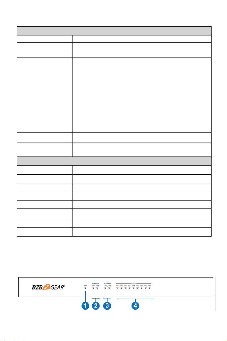
5. Operation Controls and Functions. ...............................................................................
2
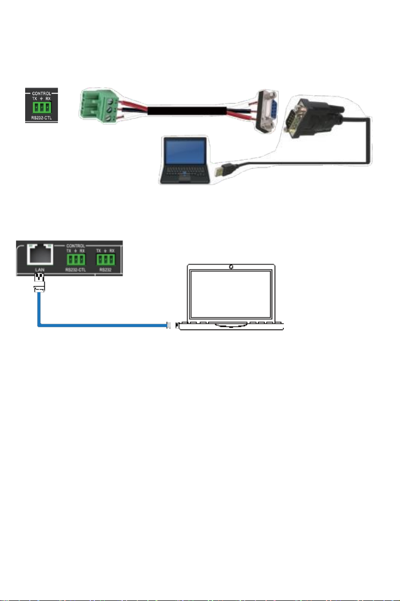
6. RS-232/LAN Control Connection. ..................................................................................
4
6.1. RS-232 Control Connection.....................................................................................
4
6.2. Network Control Connection..................................................................................
4
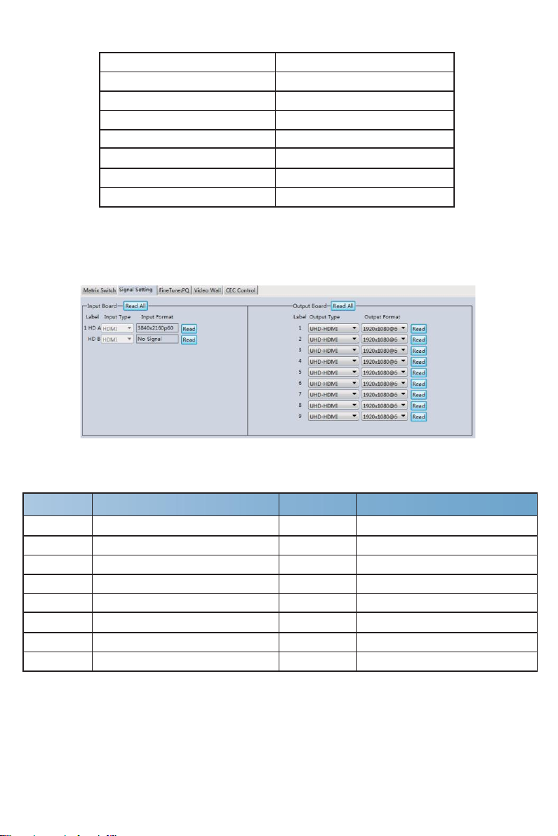
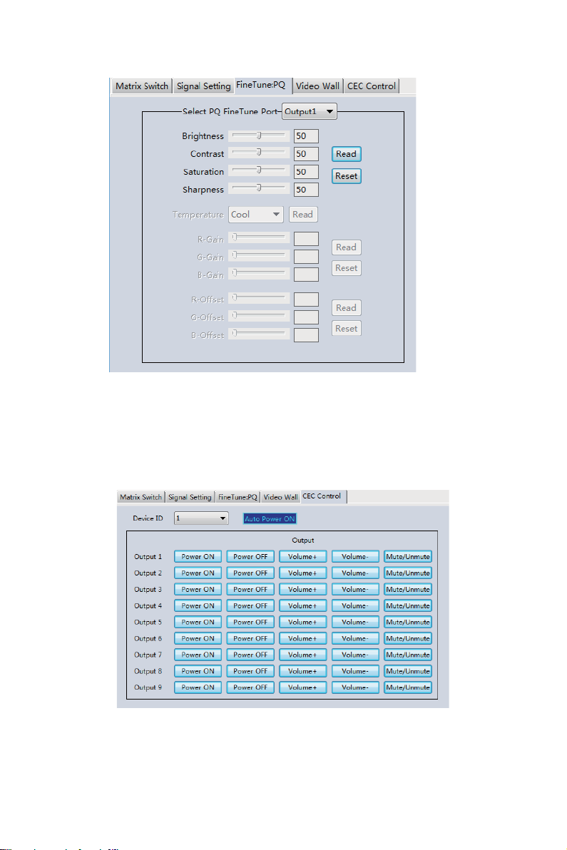
7. PC Tool User Guide. ........................................................................................................
5
8. Safety Instructions. ..........................................................................................................
11
9. Connection Diagram......................................................................................................
12
10. Tech Support……………………………………………………………………………………12
11. Warranty…………………………………………………………………………………………13
12. Mission Statement……………………………………………………………………………...13

1
1. Introduction
The BG-UHD-VW29 is an HDMI 2.0 Video Wall controller with 2 HDMI inputs, 2 HDMI loop
outs and 9 HDMI scaling outputs for video wall processing. The 5-pin phoenix connector
provides balanced L/R audio output. The product also features an RS-232 bypass feature for
daisy chain and cascade connections with different units.
2. Features
☆HDMI 2.0 and HDCP 2.2 compliant
☆Supports resolutions up to 3840x2160@60Hz video output for video wall
☆Bezel Compensation with two modes
☆2 channel HDMI loop out
☆PIP on video wall
☆180º display rotation
☆RS-232 and TCP/IP control
☆CEC control for displays viaPC Toolor commands
3. Package Contents
①1 x Ultra HD Video Wall Processor
②1 x AC Power Cord
③1 x 5-pin Phoenix Connector
④2 x 3-pin Phoenix Connector
⑤1× RS232 to Phoenix Cable
⑥1× CAT6 cable
⑦1× USB to RS232 Cable
⑧1× User Manual

2
4. Specifications
Technical
HDMI Compliance
HDMI 2.0
HDCP Compliance
HDCP 2.2/1.4
RS-232
Baud rate: 57600, data bit: 8, Stop bit: 1, no parity
1024x768@60, 1280x800@60, 1280x1024@60,
1280x960@60, 1360x768@60, 1366x768@60,
1440x900@60, 1400x1050@60, 1600x900@60,
Input Video Formats
1600x1200@60, 1680x1050@60, 1920x1200@60,
480p@60, 576p@50, 720p@50, 720p@60, 1080i@50,
1080i@60, 1080p@24, 1080p@25, 1080p@30, 1080p@50
1080p@60, 3840x2160@24, 3840x2160@25,
3840x2160@30, 3840x2160@50, 3840x2160@60,
4096x2160@24, 4096x2160@30, 4096x2160@50,
4096x2160@60
Audio Format
2.0 channel, 5.1 channel, LPCM, Dolby, AC3, DTS
ESD Protection
Human-body Model:
±8kV (Air-gap discharge), ±4kV (Contact discharge)
Mechanical
Housing
Metal Enclosure
Color
Black
Dimension
430mm (W)×220mm (D)×44mm (H)
Weight
5Kg
Supply Voltage
110-220V AC
Operating Temperature
0°C ~ 40°C / 32°F ~ 104°F
Storage Temperature
-20°C ~ 70°C / -4°F ~ 158°F
Relative Humidity
10%~50% RH (non-condensing)
5. Operation Controls and Functions
Front Panel

3
No.
Name
Function Description
1
Power LED
The power LED will illuminate when the unit is powered on.
2
INPUT LED
The LEDwillilluminate whenthecorrespondingHDMIinputportis
connected to an active HDMI source device.
3
LOOP LED
The LEDwillilluminatewhenthecorrespondingLOOPOUTport
isconnected to an HDMI display device.
4
OUTPUT LED
(1-9)
The LED will illuminatewhenthe corresponding HDMI outputport
is connectedto an HDMI display device.
Rear Panel
No.
Name
Function Description
1
INPUTS
HDMI inputs connect HDMI source devices suchas a DVD
player or gaming console with an HDMI cable.
2
LOOP OUT
HDMI signal loop out ports. Loop out the HDMI A/B signal for
devices connected to each output.
3
OUTPUTS
HDMI signal output for the video wall.
4
110-240VAC
110-240VAC power input port.
5
GND
Ground the product housing.
6
AUDIO OUTPUT
•Analog L/R audio output
•3.5mm Stereo Jack. 20Hz ~ 20kHz, 1.5Vrms max
BALANCED OUT: Balanced audio output port. 5-pin phoenix
connector, 20Hz ~ 20kHz, 1.5Vrms max.
7
SERVICE
Firmware update port.
8
CONTROL
RS232: Bypass the RS232-CTL commands to next unit.
RS232-CTL: External RS-232 control, Baud Rate: 57600
Data Bits:8, Parity: None Stop Bits:1
LAN: Network port for TCP/IP control. Connect to an active
Ethernet link with an RJ45 cable.

4
6. RS-232/LAN Control Connection
6.1 RS-232 Control Connection
The product supports RS232 Control. Connect the included RS-232 to Phoenix cable to a PC
using a USB Serial Adapter as shown in the image below:
G
PC
6.2 Network Control Connection
The product also supports Network control. Connect the LAN port of the product to a PC
using an ethernet cable as shown in the image below:
PC

5
7. PC Tool User Guide
The PC tool is an included control software that supports both UART and network control.
PC Tool consists of five parts: Matrix Switch, Signal Setting, Fine Tune: PQ, Video Wall
and CEC Control. The UI is as follows:
■Matrix Switch Tab
1. Select UART (with RS232 cable) or Network to connect to the device. Baud rate is
57600 bps.
2. Select an input source for each output.
3. “AllSet” function: Apply input HD A or B to all outputs.
4. Select the input source for B/MAIN output.
5. Select the audio source for balanced audio output and 3.5mm output.
6. Reset: Resets the device to factory settings.
7. EDID Control: Clicking the ‘EDID’ button will open the below EDID control window:
a) Read the EDID information for devices connected to
each output and save as a BIN file.
b) Open an existing EDID file and write to the HDMI
A and B input port as Manual EDID.
c) Select the predefined EDID file and write to the
HDMI A and B inputs.

6
The available predefined EDID options:
4K60-2.0CH
1920x1200-2.0CH
4K60-5.1CH
1680x1050-2.0CH
4K30-2.0CH
1600x1200-2.0CH
4K30-5.1CH
1440x900-2.0CH
1080P-2.0CH
1400x1050-2.0CH
1080P-5.1CH
1360x768-2.0CH
720P-2.0CH
1280x1024-2.0CH
1024x768-2.0CH
Manual
■Signal Setting Tab
The resolution of each input can be read to configure the resolution of each output.
Available output resolutions:
No.
Output Resolution Setting
No.
Output Resolution Setting
1
3840x2160p 60Hz
9
1440x1050 60Hz
2
3840x2160p 50Hz
10
1366x768 60Hz
3
3840x2160p 30Hz
11
1360x768 60Hz
4
3840x2160p 25Hz
12
1280x1024 60Hz
5
1920x1200 60Hz
13
1280x768 60Hz
6
1920x1080p 60Hz
14
1280x720p 60Hz
7
1920x1080p 50Hz
15
1280x720p 50Hz
8
1600x1200 60Hz
16
1024x768 60Hz
Note: 3840x2160 25/30Hz can only be used for standalone displays and not for video walls.

7
■FineTune: PQ Tab
Configure the brightness, contrast, saturation, and sharpness of each output.
Note: The recommended settings are the default 50/50/50/50. Avoid adjusting these
settings if possible. If problems arise after reconfiguration, click ‘Reset’ to return to
default settings.
■CEC Control Tab
When ‘Auto Power On’ is enabled, all displays connected to the device will turn on
when the device is powered on.
The product supports CEC function, including Power on/off, Volume+/-, Mute/Unmute.

8
■Video Wall Tab
Configure a group of outputs to function together as a video wall.
The Video Wall Setting controls manage how the displays are arranged:
1. Adjust the “Rows” and “Columns” sliders to adjust the video wall arrangement.
oThe “Available” slider sets the number screens that will be used for the
Video Wall.
oThe “Set” button sets changes made to the screen configuration.
2. Using the left mouse button, drag-select the screens that are intended for use in
the video wall. The screens selected will be shown as bright blue.
3. Open the pop-up menu by right clicking the mouse.
4. Select “Screen Stitching” from the menu to configure the video wall. The screens
selected will be shown as bright green.
5. To change the image displayed, right-click to open the pop-up menu and select the
desired input under “Input Select”. Optionally the image may also be changed
manually by following the instructions under the “Operation Controls and
Functions” section of this manual.

9
Creating a second video wall
Repeat steps 2-5 above using a different set out outputs. Please note that changing the
“Rows”, “Columns” and “Available” sliders will automatically delete the current video wall
configuration once the “Set” button is clicked. The following example shows an unusual
video wall configuration for demonstrative purposes. The video
wall configuration is of a 1x3 and 2x2 set-up:
Video Wall Context Menu
Right click on any icon to display the following menu:

10
Screen Splicing
This option connects the selected screens into a video wall configuration.
Cancel Splicing
Return the Video Wall configuration to normal outputs.
Screen 2 –
CancelSplicing
Remove a single screen from the unified video wall to display a separate
image. See the example below:
Input Select
Follow the sub-menu to change the input for the video wall display.
This function may also be used to change the input for the secondary
image as shown in the above example.
Output Select
This option is only available for a display that is not already assigned
to the video wall.
Output Type
This option is only available to a display that is not already assigned to
the video wall.
Output Format
This option is only available to a display that is not already assigned to
the video wall. This setting is for configuring the output resolution of the
unassigned display.
Mirror
Four sub-options: OFF (default), H (Horizontal), V (Vertical), and H+V.
H+V will rotate the selected display 180º.
Test Pattern
When enabled, the output will display a color bar pattern.
Bezel Setting
The Bezel Setting allows for the adjustment of the images displayed on the video wall to
compensate for the thickness of the TV’s bezel. The displays on the video wall should create a
cohesive, unified image. To achieve this, the edge of each display’s image must be removed
from the sides of displays that meet. The bezel correction may be accomplished using either
Type A Bezel Setting, or Type B Bezel Setting.
Type A Bezel Setting:
Manually remove pixels from each display’s image edge until a cohesive image is achieved.
Enter the number of pixels that need to be removed from the edges of the displays that meet.
Click “Set” to view the effects of the change and adjust if needed.

11
Type B Bezel Setting:
Measure the display from top to bottom outside the bezel. Next, measure in display from top to
bottom inside the bezel. Enter both measurement values into the entry boxes, click “Set” and the
bezel will be correct for automatically.
Bezel Compensation
The images below demonstrate a video wall set-up without bezel compensation and a video
wall set-up with correctly configured bezel compensation:
Incorrect Bezel Adjustment Correct Bezel Adjustment
Save/Load
The Save Scene/Layout and Load Scene/Layout buttons allow video wall configurations to
be saved and used at any time. The system stores up to 10 saved configurations. Each
saved configuration can optionally be given a personalized name for easier identification.
8. Safety Instructions
To ensure reliable operation of this product as well as protecting the safety of any person
using or handling this device while powered, please observe the following instructions.
1. Do not operate this product outside the specified temperature and humidity range given in
the above specifications.
2. Ensure adequate ventilation is allow for this product to operate efficiently.
3. Repair of the equipment should only be carried out by qualified professionals. This
product contains sensitive devices that may become damaged by mishandling.
4. Only use this product in dry environments. Do not allow this product to come in contact
with liquids or harmful chemicals.

12
9. Connection Diagram
Control System
Speakers
TV x 9
HDMI
AUDIO
CAT
10. Tech Support
Before contacting tech support, we may have answered your question already! Visit our
BZBGEAR support page at bzbgear.com/support for valuable information on our products.
Here you will find our Knowledge Base (bzbgear.com/knowledge-base) consisting of
tutorials, quick start guides, and step-by-step troubleshooting instructions. Also visit our
YouTube channel BZB TV at youtube.com/c/BZBTVchannel for help setting up, connecting,
and other how-to videos regarding our products.
at bzbgear.com.

13
11. Warranty
BZBGEAR Pro AV products and Cameras come with a three-year warranty. An extended
two-year warranty is available for our Cameras upon registration for a total of five years.
For an extended two-year warranty on our Cameras, follow these steps:
1. Register your Camera within 90 days of purchase by visiting bzbgear.com/warranty.
2. Complete the registration form. Provide all necessary proof of purchase details, including
serial number and a copy of your sales receipt.
For complete warranty information, please visit bzbgear.com/warranty or scan the QR code
below.
12. Mission Statement
BZBGEAR manifests from the competitive nature of the audiovisual and live streaming
industry to innovate while keeping the customer in mind. AV solutions can cost a pretty
penny, and new technology only adds to it. We believe everyone deserves to see, hear,
and feel the advancements made in today’s AV world without having to break the bank.
BZBGEAR is your answer for applications requiring the latest pro AV and live streaming
solutions.
You’ll notice comparably lower prices with BZBGEAR while the performance and quality
are on par with the top brands in the industry. Our team offers system design consultation
and expert tech support seven days a week for all BZBGEAR products. Our unparalleled
support is our way of showing we care for every one of our customers. Whether you’re an
integrator, home theater enthusiast, or a do-it-yourselfer, BZBGEAR offers solutions
allowing you to focus on your project and not your budget.

Other manuals for BG-UHD-VW29
1
Table of contents
Popular Processor manuals by other brands

UTC RETAIL
UTC RETAIL 1170 user guide

Omnia
Omnia Stereo Audio Processor Installation and operation manual

Rockford Fosgate
Rockford Fosgate 3Sixty Setup guide

Behringer
Behringer EUROCOM SPL3220 quick start guide

Winmate
Winmate T4-series user guide

Madrigal Audio
Madrigal Audio mark levinson 30.5 operating manual