C & K Systems DT-6360STC User manual

- 1 -
Ceiling Mount Motion Sensor
INSTALLATIONINSTRUCTIONS
Model
DT-6360STC
RECESS
BUCKET
DT-6360STC
RETAINER
RING
If using the retainer ring, place it through, then directly over, the
hole in the ceiling tile. Make sure to orient the retainer ring
and recess bucket as shown in Figure 1.
Next, attach the back housing of the DT-6360STC to the inside
of the recess bucket, using the same screw holes and screws
used for surface mounting [#6 (M3.5) pan head]. Pull several
inches of wiring from the ceiling through the center hole in the
recess bucket and DT-6360STC back housing.
Insert the recess bucket into the hole in the ceiling, securing it to
the ceiling (and retainer bracket) with four mounting screws.
The DT-6360STC is shipped with a special kit for flush mounting.
The kit contains a recess "bucket" and retainer ring. The retainer
ring is only needed when flush mounting the unit in ceiling tile.
Removing the tile from the ceiling (if possible) will make the
installation process easier.
FlushMounting
IMPORTANT: ToensureinsectsdonotgetinsidetheDT-6360STC
housing, make sure to seal all holes. (Recommended sealant:
silicone RTV.)
Note: If surface wiring, use the knockout hole on the side of the
housing.
If mounting the DT-6360STC directly on a ceiling, use the back
cover as a template to mark holes for the mounting screws and
wiring. Drill the holes. Then pull several inches of wiring from
the ceiling through the center hole in the back housing.
Attach the back housing to the ceiling with the mounting screws.
Recommended mounting screws: #6 (M3.5) pan head.
Surface Mounting
To remove the front cover, orient the DT-6360STC so that one of
the sides with the small rectangular slot in the center is visible.
Using a small flathead screwdriver, gently push down on the slot
while separating the housing parts. Set the front cover aside.
Remove the printed circuit board (PCB) by depressing one of
the retaining brackets at its sides. Use the microwave antenna
to carefully pull the PCB out.
MOUNTING PROCEDURE
Note: If you plan to use the DT-6360STC's tamper
switches, read theTamper Installation section on page 1.
CEILING
Figure 1
DT-6360STC
FlushMountingKit
The DUAL TEC®6360STC motion sensor provides maximum
coverage when mounted on ceilings from 8' (2.4 m) to 16' (4.8
m) high. Refer to the System Set-up section to determine which
passive infrared (PIR) mirror assembly to use at different ceiling
heights.
Choose a mounting location in the center of the protected area.
The protected area should be free of objects that might prevent
the PIR sensor from detecting an intruder: large pieces of
furniture, room dividers, etc.
Remember, infrared energy cannot penetrate solid objects. If the
PIR detector is blocked, the DT-6360STC will not trigger an alarm.
MOUNTING LOCATION
To flush mount the unit, cut a 5.5" x 5.5" (14 cm x 14 cm) hole in
the ceiling. Insert the recess bucket into the hole, using it as a
template to mark drill holes for the four mounting screws.
Remove the bucket and drill the screw holes.
The DT-6360STC is equipped with two tamper switches: a cover
tamper and ceiling tamper. When the tamper switches are used,
removing the cover from the sensor will activate the cover tamper;
removing the sensor from the ceiling will activate the ceiling
tamper. Both tamper switches are normally closed (NC) and
internally wired in series.
The cover tamper switch can be used without the ceiling tamper
and requires no modifications to the DT-6360STC housing.
To use the ceiling tamper, remove the square knockout in the rear
housing (directly behind the ceiling tamper switch), then install a
screw* in the ceiling. Leave enough of the screw protruding to
depress the tamper switch. Refer to Figure 2.
If the installation is recessed, remove the knockout from the rear
housing, drill a screw hole (behind the knockout) in the recess
bucket, then install the screw* in the recess bucket. Leave
enough of the screw protruding to depress the tamper switch.
Refer to Figure 2.
SURFACE MOUNT FLUSH MOUNT
CEILING
DT-6360STC
Screw
to depress
tamper
Screw
to depress
tamper DT-6360STCinside
recess bucket
CEILING
PINFORPCB
KEYHOLE
REAR HOUSING
KNOCKOUT
LATCH
Figure 2
Cover and Ceiling
TamperSwitches
*Note: #6 (M3.5)
pan head is
recommended.
TamperInstallation

- 2 -
SYSTEMSET-UP
The DT-6360STC package contains two PIR mirror assemblies:
oneforceilingsfrom8'(2.4m)to11'(3.3m)high,anotherforceilings
from 12' (3.65m) to 16' (4.8m) high. The unit is shipped with the
8'-11' (2.4m-3.3m) mirror installed.
To change the mirror assembly, remove the front cover and turn it
over. Next,removetheprotective capandexistingmirrorassembly
by depressing the four retaining latches at their sides. Store (or
discard) the existing mirror and install the new one. Snap the
protective cap back into place, then replace the front cover.
Changing the PIR Mirror Assembly
PIR Masking
To eliminate specific PIR zones from the pattern, mask corre-
sponding segments on the PIR mirror with the adhesive-backed
masking tape provided. Remember, segments to be masked
will be on the side of the mirror OPPOSITE the unwanted zones.
See Figure 4.
Once the tape has been applied, walk-test the sensor to ensure
that the correct mirror segments have been masked.
PIRMASKING
MATERIAL
PLACEDHERE
WILLBLOCKZONES
HITTINGHERE
Figure 4
Masking the PIR Mirrors
1
SYSTEM TESTING
DT-6360STC sensors are equipped with two diagnostic LEDs:
green for PIR and yellow for microwave. The red LED is used to
indicate an alarm condition.
Apply power to the sensor and wait until self-test is completed (90
seconds). Begin walk-testing after all three LEDs have gone out.
Figure 5
DT-6360STC PCB
2
EOL = End-of-Line (spare) terminal.
The Trouble Output is activated when a self-test failure or an INFORMER®condition occurs.
Refer to THE INFORMER CIRCUIT and the TROUBLESHOOTING sections.
Observing the proper polarity, wire the sensor as shown below
(use 22 to 14 AWG). Note: Reverse polarity will not damage the unit.
WIRING
NC COM NO V-
TAMPER SWITCH
Normally Closed
(NC) with cover on
25 mA, 30 VDC.
122
EOL TBL EOLCMD
REMOTE LED ENABLE or
COMMAND INPUT
(Self-TestInitiate)Active
Low 0 to 1.5 V Inactive
High 6 to V+ Input
Impedance 110 Kohms
(minimum).
OPEN COLLECTOR
TROUBLEOUTPUT
Vce .3V max @ 50
mA. 1K series
protection resistor.
1
Figure 3
Wiring
Diagram
ALARMRELAY
125mA, 25VDC. 22ohm
series protection resistor.
POWER
At 12 VDC,
typically
40 mA;
maximum
50 mA
Note: Do not leave excess wire inside the unit. Push as much wire as
possible into the ceiling when returning the PCB to its housing.
Note: For proper wiring methods, refer to National Electrical Code NFPA 70.
Removing Front Cover After Installation (flush mount)
After installing and walk-testing the DT-6360STC flush mount, you
may need to make adjustments. Use a screwdriver to reopen the
front cover.
Insert the screwdriver as far as it will go in the grooves inside the
recess bucket. Gently press outward to release the latches holding
the front cover in place.
DT-6360STC sensors are equipped with a microwave range
thumbwheel (R32) for range adjustment. (Refer to Figure 5.)
Set the range at MINIMUM by turning the thumbwheel all the
way to the left.
As you perform the walk-test, gradually turn the thumbwheel to
the right to increase the microwave sensitivity until the desired
ranged is obtained.
Microwave Range Adjustment
Walk-test
Walk across the protected area at the ranges to be covered.
Two to four normal steps make the diagnostic LEDs light, and
the red LED should indicate an alarm condition. When there is
no motion in the protected area, all three LEDs should be off.
COMMAND INPUT / REMOTE LED ENABLE
Position W4 determines what function the Command Input
(CMD) terminal will provide.
Installing a jumper at position W4 makes the CMD terminal
function as a Remote LED Enable terminal. If the signal to the
Remote LED Enable terminal is low, the LEDs are enabled. If
the signal to the terminal is high, the LEDs are disabled. How-
ever, if a self-test error occurs, the LEDs will light regardless of
the state of the signal.
The CMD terminal functions as a Command Input terminal when
the jumper is removed from position W4. A momentary low
signal to the terminal (at least .5 seconds) will initiate the self-
test.
LED DISABLE (Local)
To disable the diagnostic LEDs and alarm LED, remove the
jumper from position W2 on the PCB. (See Figure 5.)
*If Self-Test fails or an INFORMER condition occurs, LEDs indicates nature of problem (see Tables 1,2 & 3)
ALARM&DIAGNOSTIC LEDs:
Yellow - During normal operation LED flashes ON when a MICROWAVE event is detected.*
Green - During normal operation LED flashes ON when a PIR event is detected.* (PIR Zone Finder)
Red - During normal operation LED illuminates when an ALARM condition is triggered.*
REMOTELEDENABLE
or COMMAND INPUT
Jumper W4 installed:
CMD terminalfunctions
asRemoteLEDEnable.
Jumper W4 removed:
CMD terminalfunctions
as Command Input.
(Set toCommand Input
atfactory)
INSTALLERINITIATED
SELF-TEST
MOMENTARYSHORT
INSTALLJUMPERW3
TO DISABLE TROUBLE
OUTPUTWHENAN
INFORMER CONDITION
OCCURS
(jumper is
factory installed)
W2
REMOVEJUMPER
W2TODISABLE
DIAGNOSTICLEDS
ANDALARM LED
(jumper is factory
installed)
RED
GREEN
YELLOW
PLACEJUMPERW1
TODETERMINEPIR
SENSITIVITY
(jumper set to
normal at factory;
see page 3)
MICROWAVERANGE
THUMBWHEELR32
(setto
maximumatfactory)
TOP
BOTTOM
TAMPERSWITCH
MAX
R32
W4
W3
W1
V+
- 3 -
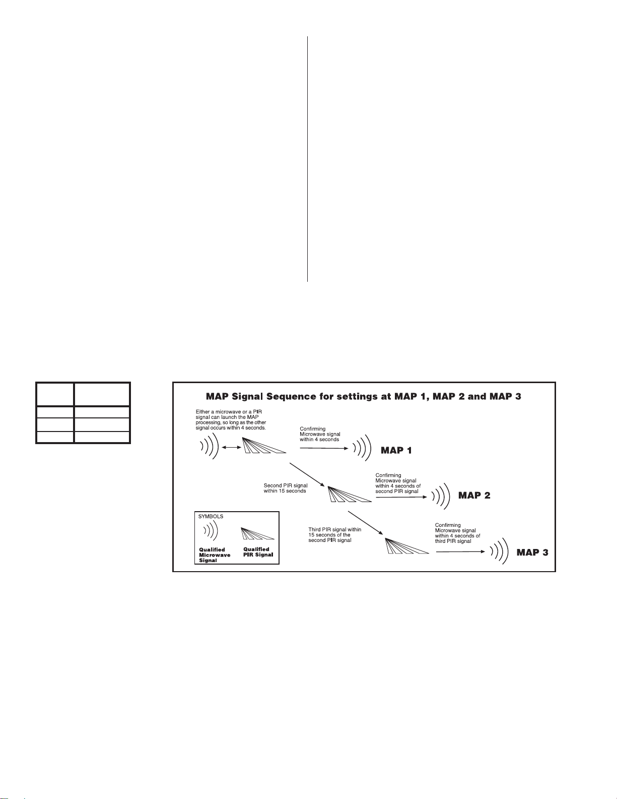
DT-6360STC sensors use the event sequence in Figure 6
(below) to determine an alarm:
If the microwave technology malfunctions (determined by a self-
test), the sensor reverts to a PIR sensor.
DT-6360STC ALARM SEQUENCE (MAP PROCESSING)
Note: An event is the detection of a microwave signal or a single
edge of a PIR signal. (The PIR pulse count is 3.)
•
If a self-test error is detected
, the self-test LED pattern
replaces the INFORMER LED pattern and the Trouble
output becomes active for eight seconds. (Refer to the
Troubleshooting Matrix on page 4.)
THE INFORMER CIRCUIT
The INFORMER circuit counts the number of events registered
by both the microwave and PIR technologies, and uses the
resulting ratio to determine if either technology is misapplied or
working properly.
The informer ratio is preset at 32 to 1. This ratio means that before
one technology registers 32 events, the other must register at
least one event. If it does not, trouble will be signaled.
When an INFORMER condition occurs, the trouble output
becomes active until the INFORMER condition is cleared, and
the LEDs display an INFORMER trouble code. (By installing the
jumper at position W3, the LEDs will display an INFORMER
trouble code, but there will be no trouble output. See Figure 5.)
The DT-6360STC immediately performs a self-test to determine if
the problem is internal.
•
Note: If eight microwave (and no PIR) events occur within one
minute, the INFORMER circuit will disable itself for eight minutes.
This feature allows the INFORMER circuit to compensate for
temporary environmental disturbances. If a PIR event occurs
during the disable period, the microwave is automatically reset.
Figure 6
MAP Signal Sequence
Important: If the LEDs are enabled by Remote LED Enable and an
INFORMER condition occurs, the LEDs will flash the INFORMER
trouble code until the condition is cleared, even if the LEDs are
subsequently remotely disabled.
M.A.P.
Processing W1 Jumper
Position
1
2
3
On pins 1 & 2
On pins 2 & 3
Removed
If no self-test error occurs
, the unit continues to display the
INFORMER LED pattern. The problem is misapplication.
Walk-test the DT-6360STC to pinpoint the cause.

- 4 -
1Return the DT-6360STC to C&K for repair.
Send the unit in for repair.1
Send the unit in for repair.1
Microwave Pulse Self-Test
Temperature Compensation
Self-Test
ALARM MW PIR
TEST DESCRIPTION (Red) (Yellow) (Green) ACTION
Table 3
Trouble Output
Troubleshooting
Matrix
ALARM MW PIR
TEST DESCRIPTION (Red) (Yellow) (Green) ACTION
DT-6360STC sensorsautomaticallyperformaseriesofself-testsin
the following instances: when the unit is powered up, when the
tests are installer initiated, upon command input, and periodically
during normal operation as on-going self-tests. When a self-test
erroroccurs,all three LEDsflash (if enabled)and the troubleoutput
becomes active until the failure is cleared. The following chart
describes how the diagnostic LEDs appear during self-tests, and
what action needs to be taken for each type of display.
Table 2 INFORMER
TroubleshootingMatrix
Note: If you enter the detection
pattern and the LEDs go off, you
canretrievethe LEDpatterntopin-
point the problem. Refer to the
Trouble Memory section below.
Power Up Self-Test
On Line - All Self-Tests Passed,
Ready for Walk-Test
1Return the DT-6360STC to C&K for repair.
Table 1
Self-Test
Troubleshooting
Matrix
The troubleshooting matrix below describes two trouble alerts
which are reported by the INFORMER circuit. To use this trouble-
shooting matrix:
1) Find the trouble alert that describes the condition of the
walk-test LEDs (with no motion in the area).
2) Walk-test the sensor, carefully watching the reaction of the
diagnostic LEDs.
3) Refer to the Possible Causes column of the matrix for an
explanationof the way in which the diagnosticLEDs reacted
to the walk-test.
Condition of LEDs
with No Motion
ALARM
(Red) MW
(Yellow) PIR
(Green) ALARM
(Red) MW
(Yellow) PIR
(Green)
Reaction of LEDs
to Walk-Test
RATIO
IMBALANCE
MW environmental problem
MW unstable
MW range too long
PIR was blocked
PIR environmental problem
PIR unstable
MW range too short
RATIO
IMBALANCE
Type of
Problem Possible
Causes
PIR range too short
PIR aimed wrong
PIR not reporting
MW range too short
MW not reporting
RATIO
IMBALANCE
RATIO
IMBALANCE
(Pattern disappears)
(Pattern disappears)
No action required.
Unit is working properly.
TROUBLESHOOTING THE DT-6360STC
Send the unit in for repair.1
On-going Self-Test
When the DT-6360STC signals a trouble output, the LEDs display
a failure pattern — all three LEDs flash at the same rate.
You can recover the individual pattern to determine what trouble
occurred. To recover the LED pattern, remove the front housing
from the unit. Use a screwdriver to connect the two (self-test) pins
at the left-hand side of the PCB (see Figure 5) and cause a
momentary short. The trouble LED pattern will reappear.
TROUBLEMEMORY Connect the pins with the screwdriver again to clear the LED
pattern.
Notes: The Trouble Memory only stores a single event (the last
event to occur) in memory. Once the LED pattern is cleared, the
memory is erased, and the self-test restarts.
The matrix below shows the individual patterns and the appro-
priate action.
LED Legend: = LED is Flashing Fast = LED is OFF
= LED is Flashing Slow = LED is ON
- 5 -
SIDEVIEW
TOPVIEW
TOPVIEW
50' (15 m)
50' (15 m)
microwave
microwave
Floor
SIDEVIEW
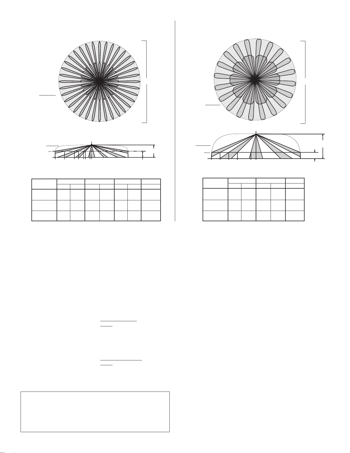
DETECTION PATTERN DETECTION PATTERN
8'-11' (2.4m-3.3m)
mirror assembly 12'-16' (3.65m-4.8m)
mirror assembly
microwave
microwave
PRODUCT SPECIFICATIONS
Alarm relay:
Energized Form C (NC)
22 ohm series protection resistor
125 mA, 25 VDC
Range:
50' (15m) diameter
[25' (7.6m) radius]
Tamperswitch:
Form A (NC)
25 mA, 30 VDC
Dimensions:
5" high x 5" wide x 2.3" deep
(12.7 cm x 12.7 cm x 5.8 cm)
Sensitivity:
2-4 normal steps
within field of view
PIR fields of view:
8'-11'(2.4m-3.3m)
mirror
Three 360ofields
36 long range zones
24 intermediate
16 short range
1 look-down
12'-16'(3.65m-4.8m)
mirror
Two 360ofields
40 long range zones
20 intermediate
1 look-down
Troubleoutput:
Open collector
voltage between
collector and
emitter (Vce) is
.3V max at 50 mA
(For future use)
PIR white light
immunity:
900LUX
Power requirements:
10 - 12.9 VDC ,
typically 40 mA
50 mA maximum,
AC Ripple: 3 V peak-
to-peak at nominal
12VDC
Operating
temperature:
32oto 120o F
(0oto 49oC)
Weight:
14 oz (397 g)
Relative
humidity
5% to 95%
(non-condensing)
Approvals/listings:
CE (EMC Directive)
FCC certified
UL listed
*ULC listed
IC certified
Standardaccessories
included:
DT-6360STCrecesskit;
PIR masking material
Command input:
Self-test initiate
Active low 0 to 1.5V
Inactive high 6 to V+
Input impedance
110K (minimum).
(For future use)
RFimmunity:
30 V/m,
10 MHz-1000MHz
Frequencies:
Center band -
10.525 GHz (USA),
may vary in other
countries
For UL certificated installation, the DT-6360STC must be con-
nected to a UL listed power supply or UL listed control unit
capable of providing a minimum of four hours of standby power.
Important Notices *The ULC label or listed marking on a product is the only evidence
provided by Underwriters Laboratories of Canada to identify products
that have been produced under the Listing and Follow-up Service.
4' (1.2m)
Above Floor
GFEDCBA
Mounting Height
4' (1.2m) Floor
4' (1.2m)
Above Floor
EDCBA
4' (1.2m)
Mounting Height
CENTER
MOUNTING
HEIGHT
12' (3.65m)
14' (4.2m)
16' (4.8m)
OUTER TIER INNER TIER E
2.3'
(0.7m)
3.4'
(1.04m)
2.9'
(0.9m)
AB C D
19.8'
(6m)
24.8'
(8m)
29.7'
(9m)
16.0'
(4.8m)
24.0'
(7.3m)
12.1'
(3.68m)
15.2'
(4.6m)
18.2'
(5.5m)
8.3'
(2.5m)
10.3'
(3.1m)
12.4'
(3.78m)
20.0'
(6m)
CENTER
MOUNTING
HEIGHT
8' (2.4m)
9' (2.7m)
11' (3.3m)
OUTER TIER MIDDLE TIER INNER TIER
AB CDEF
25.3'
(8m)
31.6'
(9.6m)
44.3'
(13.5m)
18.8'
(5.7m)
23.5'
(7m)
33.0'
(10.1m)
11.8'
(3.6m)
14.8'
(4.5m)
20.7'
(6.3m)
9.0'
(2.7m)
15.8'
(4.8m)
5.6'
(1.7m)
7.0'
(2.1m)
9.8'
(3m)
4.3'
(1.3m)
5.4'
(1.7m)
7.5'
(2.3m)
G
1.7'
(0.5m)
2.1'
(0.6m)
2.9'
(0.9m)
11.3'
(3.4m)
The DT-6360STC should be tested at least once each year to
ensure proper operation.

- 6 -
NOTICES
FCC
This equipment has been tested and found to comply with the limits for a
field disturbance sensor, pursuant to Part 15 of the FCC Rules. The user is
cautioned that changes or modifications not expressly approved by C&K
Systems could void the user's authority to operate this equipment.
This equipment has been tested and found to comply with the limits for a
classBdigitaldevice,pursuanttoPart15oftheFCCRules. Theselimitsare
designed to provide reasonable protection against harmful interference in
a residential installation. This equipment generates, uses and can radiate
radiofrequency energy and,ifnot installedandused inaccordancewith the
instructions, may cause harmful interference to radio communications.
However,thereisnoguaranteethatinterferencewillnotoccurinaparticular
installation. If this equipment does cause harmful interference to radio or
television reception, which can be determined by turning the equipment off
and on, the user is encouraged to try to correct the interference by one or
more of the following methods:
- Reorient or relocate the receiving antenna.
- Increase the separation between the equipment and receiver.
- Connect the equipment into an outlet on a circuit different from
that to which the receiver is connected.
- Consult the dealer or an experienced radio/TV technician for
help.
Industry Canada
This device complies with RSS-210 of Industry and Science Canada.
Operation is subject to the following two conditions: (1) this device may not
cause interference, and (2) this device must accept any interference,
including interference that may cause undesired operation of the device.
This Class B digital apparatus meets all requirements of the Canadian
Interference-Causing Equipment Regulations.
Cet appareil numérique de la classe B respecte toutes les exigences du
Règlement sur le matériel brouilleur du Canada.
C&K is a registered trademark of C&K Components, Inc.
DUALTECandINFORMERare registeredtrademarksofC&K
Systems,Inc.
Copyright 1996 C&K Systems, Inc.
5-051-312-00 Rev D http://www.cksys.com
Table of contents
Popular Accessories manuals by other brands


Roland
Roland TM-6 PRO manual

Leuze electronic
Leuze electronic MC3x Series Original operating instructions

Endress+Hauser
Endress+Hauser Cleanfit P CPA472D operating instructions

Panasonic
Panasonic WX-LA20 manual

Balluff
Balluff IO-Link BOS R080K-XM-RS10 S4 Series user guide

Somogyi Elektronic
Somogyi Elektronic home NV MS 2+6 instruction manual

Aqua-Scope
Aqua-Scope RANLWE01 quick start guide

Orbita
Orbita AVANTI 24 Instruction guide

Invacare
Invacare T1358 Assembly, installation and operating instructions

Cognex
Cognex In-Sight 2000 Mini PoE Series reference guide

Ecolink
Ecolink Tilt Installation & operation manual

HORL
HORL ROLLING SHARPENER manual