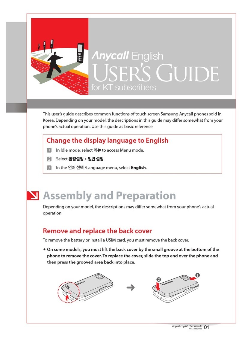
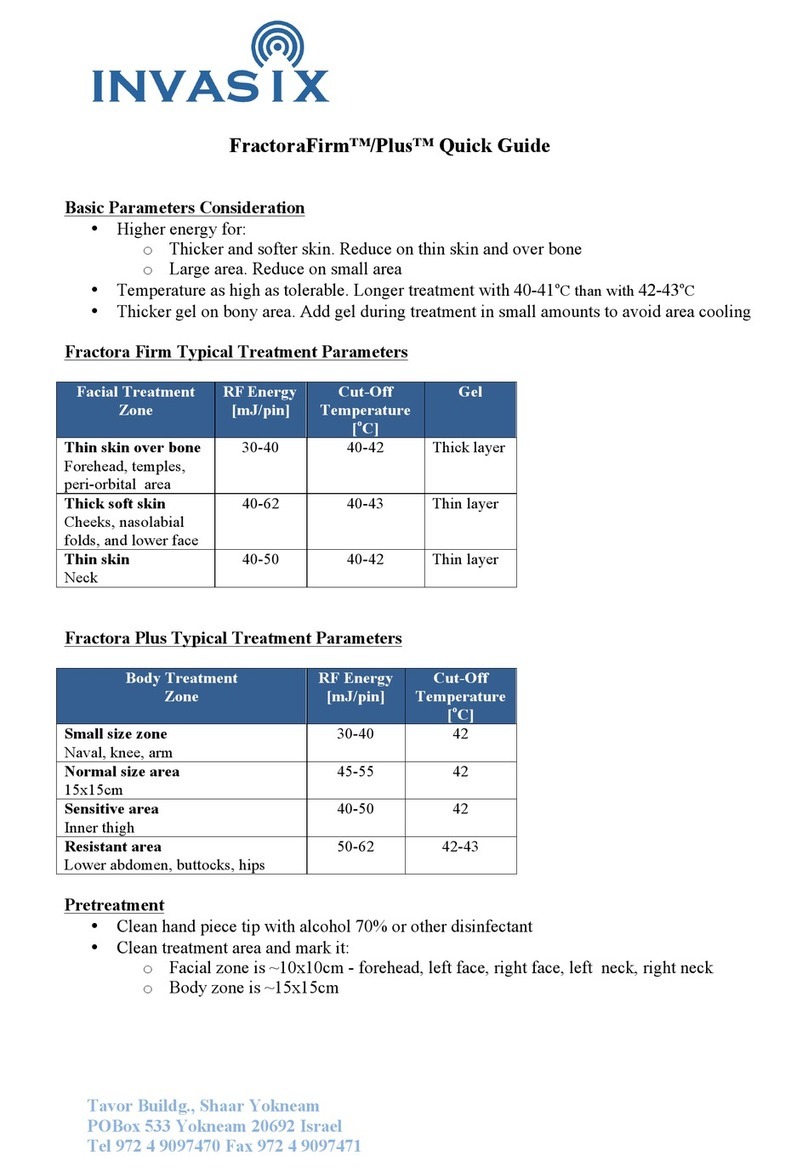
C & K Systems ACTIVE 5 Installation and operation manual

ACTIVE 5
ENGINEERING
MANUAL
C & K Systems Ltd C031-066 Issue 3

C&K Securitech 1
THE ACTIVE 5 INSTALLATION MANUAL.
Date: Feb 1997
INTRODUCTION.
The Active 5 is a microprocessor controlled intruder alarm panel. It features five
zones all of which are programmable. A non volatile memory holds the
programming options. These will be retained in total power failure. It Is designed
to be simple to program and allow flexibility in use.
SYSTEM PLANNING
When the panel reaches you it will be factory programmed. This is done for
testing purposes but can also be used for installation if required. This present
program is referred to as 'factory defaults'. It is advised that the engineer should
be familiar with all the features & options before attempting to program.
The Active 5 should ideally be installed out of sight but remain accessible. The
panel, and its keypads (if used) should be mounted within the area covered by
the alarm system. Up to 3 remote keypads can be used on the system. The
positioning of these should be agreed with the user once the entry/exit routes
and the Part Set functions have been explained to them.
SPECIAL FEATURES
The Active 5 has some special features to ensure correct operation of the alarm
system at all times. The control status is stored in the non volatile memory, this
allows the panel to remain 'Set' even after a total power failure. To prevent
repeated false alarms, if three consecutive alarms occur from any alarm zone
during the 'SET' period, that zone will automatically be isolated.
USER/CUSTOMER CODE DEFAULTS
If at any stage you want to restore the panel to its factory defaults, place the
small jumper link (supplied with the spare fuses) onto the memory default link
located to the right of the keypad on the main PCB. It will be clearly marked
either LK2 or CN6. Remove the supply from the control panel (batteries and
mains) then restore power. Now remove the link and the panel will have been
restored back to factory defaults.

C&K Securitech 2
FACTORY DEFAULTS
User / Customer Code 1 1234
Engineer Code 7890
Circuit 1 Personal Attack (PA)
Circuit 2 Alarm circuit
Circuit 3 Alarm circuit isolated in home set
Circuit 4 Alarm circuit with walkthrough
Circuit 5 Entry / Exit circuit
Full set exit time 30 seconds
Night set exit time 15 seconds
Entry time 30 seconds
Bell ring time 15 minutes
These programming defaults are what the panel will revert to if a factory reset is
performed. The panel should come to you programmed in this way however if for
some reason you find it not to be the same, simply perform a factory reset and
this will revert the panel to the above settings.
SPECIFICATION FOR SOFTWARE REVISION NUMBER V3.0
The software revision number can be located on the top of the main processor
Power Supply
Mains Supply Voltage 230 v AC Nom
PSU output voltage 13.6 v DC Nom
Maximum output current 1 amp (total)
Aux current 500 mA Max.
Battery Fuse 1 A (20 mm)
Panel Quiescent 40 mA
Maximum Cable Run 100 Metres
General
Operating temperature 10 to 50 degrees centigrade
Humidity Up to 80% non condensing
Dimensions 304 mm (W)
220 mm (H)
89 mm (D)
Control Panel Weight 1.45 kg Excluding Batt
Stand by Battery 2.6 Ah 12 v Rechargeable
6 Ah max.

C&K Securitech 3
Mounting
ARemove the lid screws and remove lid.
BUnplug any cables connected to the PCB
CRemove the PCB.
DPlace the panel in the selected position and mark the three fixing holes.
EMount the Panel securely using all three positions.
FReplace PCB and reconnect all cabling.
WIRING THE CONTROL PANEL
1 Mains connection
Mains connection should be made through the entry point located towards the
bottom of the panel and the cable must be separate to all other wiring. The cable
MUST be earthed and we recommend power is taken from a 3 Amp fused spur
and wired by a qualified electrician.
2 Battery connection.
The Active 5 requires a standby battery to be fitted to provide power in the event
of mains failure. A sealed lead acid battery should be fitted (maximum 6 Ah).
3 Detector circuits
Connections are provided for up to five detector circuits on which normally
closed detection devices should be used. One or more devices may be
connected to each alarm circuit. These should be connected in series. The
circuit connections are located to the bottom right of the PCB.

C&K Securitech 4
4 PIR Latch Line (L+)
In the event of two or more PIR detectors being fitted to any zone, latching
detectors can be used. The 'L+' connection provides this function. It is low (0V)
when unset and high (12 v) when set.
5 Detector reset (ID)
Some detectors require the removal of power to reset (e.g. Viper Plus or Smoke
detectors). The 'ID' output should be used as the negative supply for these
devices. The positive supply should be taken from the AUX 12+.
6 Internal sounders (Speaker)
The control panel is fitted with a 35 Ohm speaker in the housing to aid in audible
alarms. If an extra speaker/s is required, it should be connected to the terminals
marked SPK+ & SPK-. A maximum of two 16 ohm speakers may be fitted in
parallel. (see diagram B)
7 External Sounder & Strobe.
Connection for external sounder and strobe are shown in diagram B. Please
note the bell trigger shown is applied negative. (Negative bell ring).
ST - Strobe switched negative.
S- Siren switched negative
H- Siren hold off (negative, going positive in alarm)
BELL+ Relay common..
WIRING DIAGRAM FOR SOUNDERS SHOWN ON BACK PAGE
Diagram B

C&K Securitech 5
8 AUX DC Detector power.
The auxiliary power is provided from connections marked 'AUX'. This is to
provide the 12 v supply for detectors e.g. PIR's. The auxiliary power output is
rated 500 mA max. (12 v nominal).
**PLEASE NOTE BELLBOX CONNECTIONS AT REAR OF MANUAL**
MOUNTING A REMOTE KEYPAD
1) Having identified the position of the remote keypads to be fitted, mark the
holes for the mounting position.
2) Screw the backbox in the agreed position.
3) Note the rear entry of cabling
WIRING A REMOTE KEYPAD
1) The remote keypads require 6 core cable for their connection to the main
control panel.
2) Connect the cable as shown below in diagram C
3) Individual keypads do not need to be identified to the system. (i.e. addressed)
DIAGRAM C
SETTING OPTIONS.
The Active 5 can be operated with a remote keyswitch or remote keypad.
Three methods of setting may be used.
i) Timed exit
ii) Exit terminate
iii) Door sense setting

C&K Securitech 6
i)
Timed exit can be used by simply programming the time you wish using the 3-0
and 3-3 options.
ii)
Exit terminate is achieved by connecting the push button across S+ and S2 and
program option 7-3-1 from engineering mode. Make sure you link S1 to S+. This
will stop the panel seeing a telephone line fault.
When the push button is pressed the panel will omit an chime tone, the exit tone
will continue for a further 8 seconds, then the chime tone will sound again, the
system is now set. The chime tone is suppressed in night set. Infinite exit time is
possible for full set only, by setting the exit time to zero (option 3-0-0).
iii)
Door sense setting is achieved in a similar way to exit terminate. You will still
require the link between S1 and S+. You also need option 7-3-1 programmed.
Your contact or shunt lock needs to go between S2 and the right hand terminal
of the exit zone
LINE FAULT INPUT
If you are using the Active 5X which is a comms version of the Active 5
control panel, you will be able to utilise the line fault terminals. These are a pair
of contacts which should be connected to a relay output of a communicator.
They will need to be wired between S1 and S+
ALARM OUTPUTS.
* Timed audible alarm relay. form C rated 2.5A for external sounder.
* Strobe output. Open Collector. Latched until user resets the panel.
300mA output capacity.
* Internal sounder speaker 35 Ohm & output for 2 x 16 ohm max. To follow
all keypad sounds except keypad depression confirmation beeps.
* Latched Fire alarm voltage trigger. High going low in alarm. Restore on
system reset. 5mA at 12v DC.
* Latched panic alarm voltage trigger. Output high going low in
alarm. Restore when system is reset. 5mA at 12v DC.
* Latched alarm voltage trigger. Output high going low in alarm
Restore when system is reset. 5mA at 12v DC

C&K Securitech 7
INITIAL POWER UP
NOTE The lid should be kept off the main control panel. The keypad tamper
may also be used to enter engineer mode.
i Switch the mains supply on, the internal sounder will start.
ii Enter 1 2 3 4 followed by # button, this will silence the sounder and the
TAMPER LED will then flash.
IF NO PROGRAMMING IS REQUIRED, REPLACE THE LID. REFER TO
USER HANDBOOK FOR USER OPERATING INSTRUCTIONS.
iii To enter programming mode enter 7 8 9 0. The TAMPER LED will go out
and the MAINS LED will flash.
Follow the step by step instructions for programming. The programming can be
done in any order. Therefore it is possible to change only one option then exit
from engineering mode.
*NOTE* EXITING ENGINEERING MODE:
To EXIT engineering, confirm any options you have selected with the * (STAR)
key. Then either close ALL tamper circuits and wait for approximately 60
seconds whereby the panel will jump out of engineering mode automatically.
Pressing the # (HASH) key will manually exit engineering.
If for any reason you need to return to engineering mode, you can enter your
engineering code ( default as 7 8 9 0 ) and then open a tamper circuit, the
easiest way to do this is to remove the panel or keypad lid.
OPTION 1-1. ENGINEER CODE. DEFAULT 7890.
Used to get into the progr amming section of the control panel and for
engineer only reset. Enter 1-1 and four LEDs will illuminate. Enter your
new 4 digit code and you will hear an accept beep. If you hear an error
tone then the code was not valid and has not been changed.
OPTION 7-9. FULL SET BELL DELAY. 1 to 21 mins. DEFAULT 0 (NO DELAY)
Used to delay audible and visual signalling, following a remotely signalled
alarm. Enter 7-9 - no LEDs will light up. This has been preset for factory
default at 0 minutes. A new time may be programmed by entering the
keys which total up to the required amount e.g. You require 7 minutes bell
delay so you would select 6 and 1. Press * to confirm. The accept tone
will sound.

C&K Securitech 8
OPTION 3-0 EXIT TIME 5-105 Seconds. DEFAULT. 30 secs.
Enter 3-0 - LED 6 will light up. This has been preset for factory default - at
30 seconds. A new time may be programmed by entering the relevant
keys which total up to make the required time multiplied by 5. Once
program is set press * to confirm. The accept tone will sound.
Example of setting 30 seconds 6x 5 = 30
Example of setting 60 seconds 1+5+6 x 5 = 60
Example of setting 105 seconds 1+2+3+4+5+6 x 5 =105
OPTION 3-1 ENTRY TIME 5 - 105 seconds. DEFAULT 30 secs.
Enter 3-1 - LED 6 will light up. Again this has been preset for factory
default at 30 seconds. To reprogram the entry time follow exactly the
same directions as the EXIT TIME. Again press * to confirm option. The
accept tone will sound.
OPTION 3-2 BELL DURATION 1-21 minutes. DEFAULT 15 mins.
Enter 3-2 - LEDs 6,5 and 4 will light up. This has been preset for factory
default at 15 minutes. A new time may be programmed by entering the
keys which when totalled up come to the desired time. Once program is
set. Press * to confirm. The accept tone will sound.
Example to program 21 minutes 1+2+3+4+5+6 = 21 minutes
OPTION 3-3 NIGHT SET EXIT TIME 5 - 105 seconds. DEFAULT 15 secs.
Enter 3-3 - LED 3 will light up. This has been preset for factory default 15
seconds. A new time may be programmed by the same procedure as for
the other entry and exit timers. Press * to confirm. The accept tone will
sound.
OPTION 4-X. ZONE PROGRAMMING.
Enter 4 plus the zone number, for example 4-3 will allow programming for
zone number 3. Using the chart below program the desired options for
that zone. There are 6 primary zone types. Alarm, Full set entry zone,
Night set entry zone, 24 hour zone, Fire zone and Personal attack zone.
Working to the right of the zone type are zone attributes and one or more
can be added. If a zone is pre-programmed pressing the 0 key will clear
the entry.

C&K Securitech 9
CIRCUIT PROGRAMMING MATRIX REFERENCE GUIDE
LED 1 LED 2 LED 3 LED 4 LED 5 LED 6
TAMPER LED
ALARM ISOLATE IN
HOME SET ISOLATE IN
NIGHT SET WALK THROUGH
ENTRY ROUTE CHIME ISOLATE
PERMIT
FULL SET
ENTRY ZONE NIGHT SET
ENTRY ZONE WALK THROUGH
ENTRY ROUTE CHIME ISOLATE
PERMIT
24 HOUR ZONE BELLS &
STROBE WARNING
TONE
FIRE BELLS &
STROBE
P.A.
VIEW FROM LEFT TO RIGHT. USE KEY 1 TO 6 TO SWITCH LED ON OR OFF.
ZONE TYPES ARE SHOWN IN BOLD TYPE. COLUMNS TO THE RIGHT OF THE
ZONE TYPE SHOW APPLICABLE OPTIONS. MORE THAN ONE PER ZONE TYPE
MAY BE SELECTED. SELECT A PRIMARY OPTION (BOLD TEXT) THEN SELECT
ANY SECONDARY OPTION BY GOING TO THE RIGHT FROM THE ONE YOU
CHOOSE. IN ROW 2, FULL SET ENTRY AND NIGHT SET ENTRY MAY BOTH BE
APPLIED TO THE SAME ZONE. LED NUMBERS AT THE TOP OF THE CHART DO
NOT REFER TO THE ZONE NUMBER.
ZONE ATTRIBUTES AND MEANINGS .
ALARM. A standard alarm zone. This zone will signal alarm if tripped
while the control is in the fully armed condition. In the day condition visual
indication may be programmed. (option 7-4-1)
FULL SET ENTRY ZONE. This zone type controls the entry and exit to
and from the alarm system. When the control is armed tripping the zone
will start a timed entry period during which time the system should be
disarmed. Failure to do so will result in a full alarm condition. When
arming is requested this is the last zone to pass through before leaving
the system. It can be fully set using a timer or by seeing the last sensor
close or reset. (final contact closure). Alternatively a terminator set button,
outside the protected area can arm the system, if all zones are clear. If a
zone is programmed for both Full set and Night set entry it can be final
contact setting in the former and timed entry/exit in the latter.
NIGHT SET ENTRY ZONE. This zone type has the same attributes as the
Full set entry zone except that it is associated with one of the night set
conditions. Night Set or Home Set. Even when the system is only partly
armed we still need some method of entering and leaving it. Although a
single zone may be programmed for both types of operation it may also
be 2 different ones.

C&K Securitech 10
24 HOUR ZONE. This zone type is active 24 hours a day irrespective of
whether the control panel is armed or disarmed. In the armed condition it
will signal a full alarm if triggered. In the disarmed condition it will give a
local internal alarm warning only.
FIRE. A 24 hour type of zone which will accept connection of 12 volt, 4
wire smoke detectors. Activation will cause a pulsed sounder output to
differentiate from other alarm signals.
PERSONAL ATTACK ZONE. A 24 hour type of zone which is to be
connected to personal attack switches. The zone gives full alarm
condition when tripped and an option is available to make it silent.
(remote signalling trigger only).
ISOLATE IN HOME SET. An option which can be selected with alarm
type zones. This will make the zone in-operative during the Home set
arming period. Home set arming cannot be selected until one zone has
had this option selected.
ISOLATE IN NIGHT SET. An option which can be selected with alarm
type zones. This will make the zone in-operative during the Night set
arming period. Night set arming cannot be selected until one zone has
had this option selected.
WALK THROUGH ENTRY ROUTE. An option which can be selected with
alarm type zones. The zone will act as an extra exit zone, allowing
passage out of the premises. If tripped after the entry period is started it
will allow walk through to the control or keypad. If tripped before it will act
as a normal alarm zone.
CHIME. An alarm zone option which causes the internal sounder to emit a
chime sound if the zone is opened during the disarmed, or day condition.
ISOLATE PERMIT. An alarm zone option which allows the user to set the
system and manually isolate this zone. The zone will be disarmed for the
period of one arming only. The next time the panel is set, this zone would
be armed again. Without this option programmed, no manual isolation of
this zone is possible. (See users manual for manual isolate permit usage)
BELLS AND STROBE. A 24 hour zone option which, following and alarm
in the day condition, allows full audible and visual warning instead of
internal only.

C&K Securitech 11
WARNING TONE . A 24 hour zone option which, following and alarm in
the day condition, allows the internal alarm sounder tone to be changed to
a rapid beeping. This will give a differential to other day time alarms.
EXAMPLE TO PROGRAM ZONE 1
ENTER 4-1. The TAMPER LED will show programmed as PA from factory
default.
To remove this option enter 0. The 0 key will remove all existing options so that
any or all LEDs that were showing will extinguish. The 0 key will only do this
after you have entered 4-1 and are in the programming options.
Now that the zone is totally cleared, select the primary option for this zone. The
secondary options are now available. If you want zone 1 to be programmed as
the final exit (FX) with the chime option, first select 4 -1 then clear the previous
selection by pressing the 0 key and illuminate LED 2 followed by LED 5.
Then press * to confirm. Accept tone will sound.Follow this procedure for all or
any zones you want to program.
NOTE...
All entry zones are isolated in home set.
Full set entry acts as normal alarm in night set.
Night set entry acts as normal alarm in full set.
If you require entry in both full and night set select both options on the same
zone.
OPTION 5. ENGINEER EVENT LOG REVIEW
The engineer log is organised into SET and UNSET events. The log will show
the first and subsequent alarms and isolated zones. First to alarm is shown by
the relevant LED being 'on'. Subsequent alarms are shown by the LED flashing
and isolated zones are shown by LED pulsing slowly. The buzzer will sound
whilst viewing the 'SET' logs and silent whilst viewing the 'UNSET' logs.
To view the engineer logs proceed as follows
From the program mode press the '5' key. The log routine will start with DAY 1
SET. The remaining logs are viewed by pressing the relevant key '2' for 2nd, '3'
for 3rd etc. on to log 9. Pressing the '0' key gives the last alarm condition for
both 'SET' and 'UNSET'.
The # key will alternate between 'SET' and 'UNSET' logs and can be used at
anytime. To exit logs press the * key.

C&K Securitech 12
7-X OPTIONS.
The 7 Options controls how the panel responds to given criteria. Some options
only apply if a communicator is fitted (Active 5X only) these are marked with a ⊗.
OPTION 7-0. NIGHT SET OPTIONS.
70-1 Night set disable
70-2 Disable bells in Night set
70-3 ⊗Disable Communicator in Night set
70-4 Instant Set in Night set
OPTION 7-1. HOME SET OPTIONS.
71-1 Home set disable
71-2 Disable bells in Home set
71-3 ⊗Disable Communicator in Home set.
OPTION 7-2. ENGINEER OPTIONS.
72-1 Eng. only alarm reset. After a remote signalling alarm from the
ALARM trigger the system may only be reset by the installer or his
representative. Entry of the Engineer code is required befo re the
system will set again.
72-2 Eng. only PA reset. Following a PA alarm, which has been remotely
signalled the system must be reset by the installer or his
representative. Entry of the Engineer code is required before the
system will set again.
72-3 ⊗Silent P.A. alarm. If selected then any zone programmed as a P.A.
zone will send only a remote signal. The sounders and strobe light
will be suppressed.
72-4 ⊗45 Second communicator delay after alarm condition occurs
OPTION 7-3. LINE FAULT OPTIONS.
73-1 Convert keyswitch S1 & S+ to Line Fault
73-2 Disable Setting when a line fault is present.
73-3 Silent line fault
73-4 Suppress LED Display of line fault after 12 seconds.

C&K Securitech 13
OPTION 7-4. EUROPEAN OPTIONS.
74-1 Flash the LED relating to a zone if that zone if it is OPEN when the
control panel is in an UNSET condition
74-2 ⊗2 Stage Communicator output
74-3 10 minute auto isolate of an open zone when set.
74-4 BLOCKSCHLOSS - German Setting Method.
BELLBOX CONNECTIONS
ACTIVE 5 PANEL ST- S- BELL+ LEFT HAND
TAMPER RIGHT HAND
TAMPER
SONADE 2000 STROBE- BDAT
FLASHGUARD XL+ STROBE- SIREN- SUPPLY+ SUPPLY- TAMPER
OUT
STARLIGHT 2000 ST -R +H -H RTN
ACTIVEGUARD STB- -S +12V -12V RIGHT
HAND
TAMPER
ACTIVE GUARD 3 ST- -SW V+ V- RET
SECURIGUARD STROBE- S- SUPPLY+ SUPPLY- LEFT
HAND
TAMPER
NOVA GUARD 2+T STROBE- S- 12V+ 12V- R
SPIRIT AU1000 STB- TRG- HOLD
OFF + HOLD
OFF - RTN-
GENERAL
TERMINALS STROBE
TRIG - SIREN
TRIG - SUPPLY+ SUPPLY- TAMPER
RETURN
You MUST check your bellbox instructions to see if you are required to make
any other links.
These terminals are given in good faith but without warranty. The manufacturers
of the bellboxes shown above have the right to change terminals without
notification to C&K systems or to you, the end user.
This product should only be used for domestic, commercial and
light industrial use only.

C&K Securitech 14
ZONE ZONE USE / LOCATION RESISTANCE KEYS
ENTERED
1ΩΩ
2ΩΩ
3ΩΩ
4ΩΩ
5ΩΩ
TIMER VALUE KEYS ENTERED
FULL SECONDS
NIGHT SECONDS
EXT SOUNDER MINUTES
DELAY MINUTES
TICK BOX 1 2 3 4 CHECKED
NIGHT SET OPTIONS
HOME SET OPTIONS
ENGINEER OPTIONS
LINE FAULT OPTIONS
EUROPEAN OPTIONS
BATTERY VOLTAGE V
AUX VOLTAGE V
INSTALLED BY
THIS INFORMATION SHOULD BE KEPT EITHER INSIDE THE CONTROL PANEL OR WITH THE INSTALLER. IT CAN
BE USED TO REFER TO PROGRAMMING DETAILS WHEN NEEDED.
C&K Systems Ltd.
Unit 24 Walkers Road
North Moons Moat Industrial Estate
Redditch
Worcs.
B98 9HE
Tel : +44 (0)1527 68111
Fax : +44(0)1527 68222
Technical Support : 0345 660533 9am - 5pm weekdays
Local rate call only - UK Only
BS EN ISO No.9002:1994
Certificate No. 0944
Table of contents
