Error Compensation
Direction
Radius / Diameter
SETUP, Radius / Diameter, Direction, Error Compensation C70 Digital Readout System
NOTES
The Diameter setting is
useful for lathes, and
other turning
applications, to display
diameter rather than
radius.
The Direction setting is
quite arbitrary. Set it to
whichever makes most
sense to the machine.
NB, Direction is
dependent on where the
scale is mounted
If Error Compensation is
applied, it is important
that is absolutely correct.
If it is not correct, errors
could be increased rather
than reduced.
After setting up the Error
Compensation, it is
advisable to check its
effect in normal
operation.
Segmented
Compensation need not
be over the entire scale
length.
It can be applied just to a
length of high
importance, or it can be
as small as one segment.
Newall Measurement Systems Ltd10
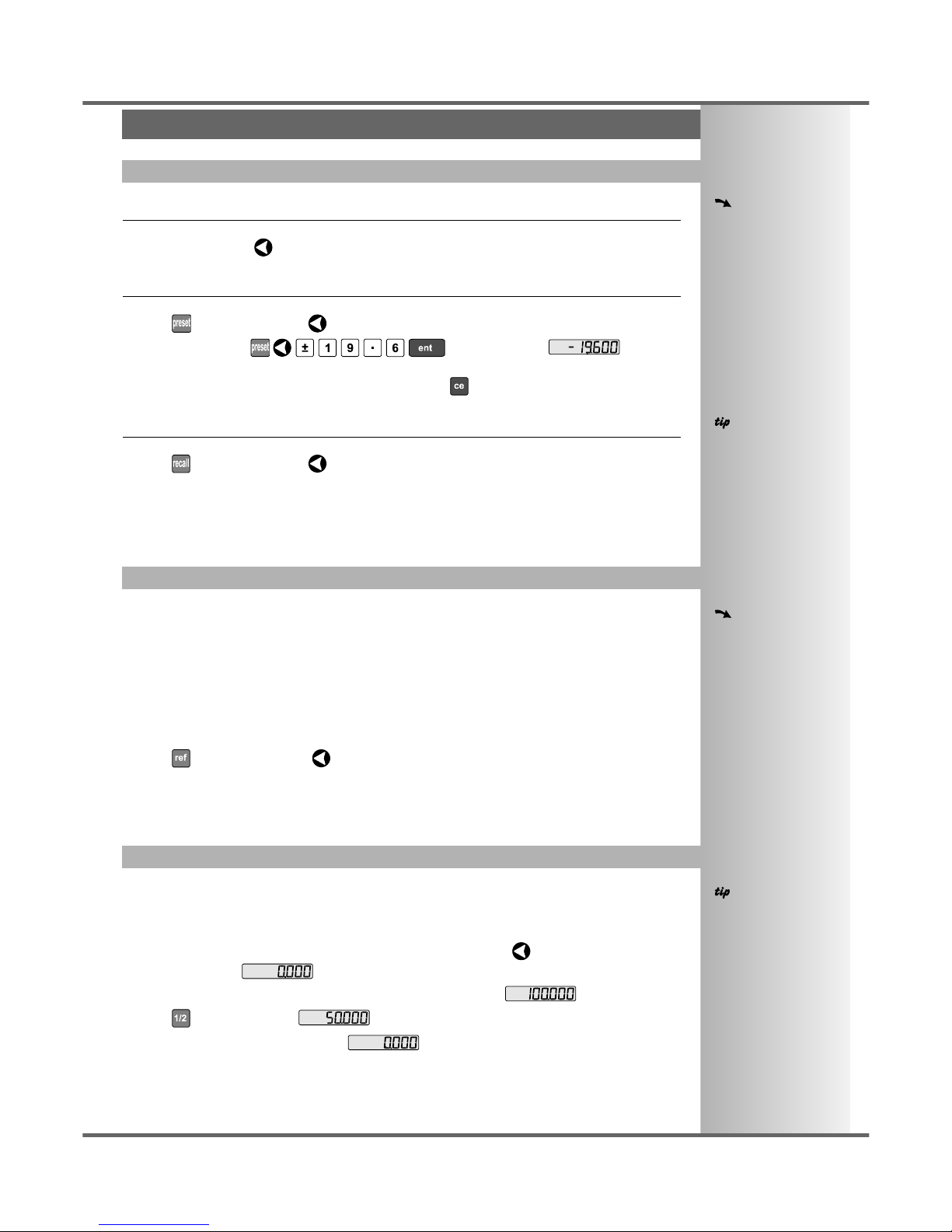
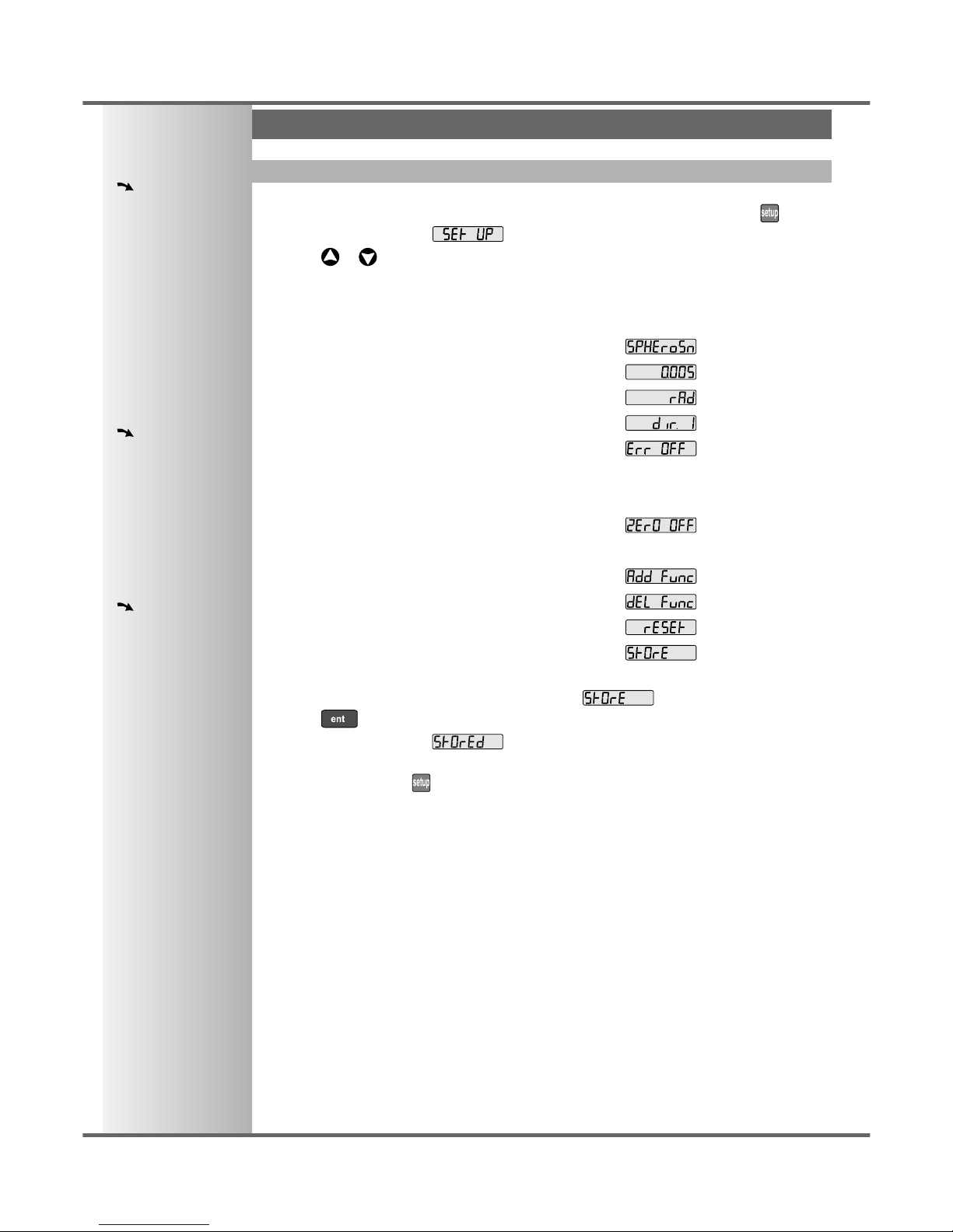
Selecting the Diameter setting causes the C70 to display double the actual movement on any axis.
There are two possible settings for each axis:
Radius
Diameter
•Press the Select Key next to the , or to cycle between the two settings for each axis.
The Direction setting allows you to match the C70 to the actual direction of travel of any axis.
There are two possible settings for each axis:
•Press the Select Key next to the , or to cycle between the two settings for each axis.
Errors can result from a number of sources, including machine wear. Where the degree of error increases
linearly along the length of travel of the scale, Linear Error Compensation should be applied. However,
where the errors are local to an area of travel, the Segmented Error Compensation should be applied.
There are three possible settings for each axis:
Off
Segmented Compensation
Linear Compensation
•Press the Select Key next to the , or to cycle between the three settings for each axis.
If one or more axes are set to Segmented Error Compensation, or Linear Error Compensation, then
the next setup option will be to configure the compensation for each of those axes.
•Press .
The middle display changes to .
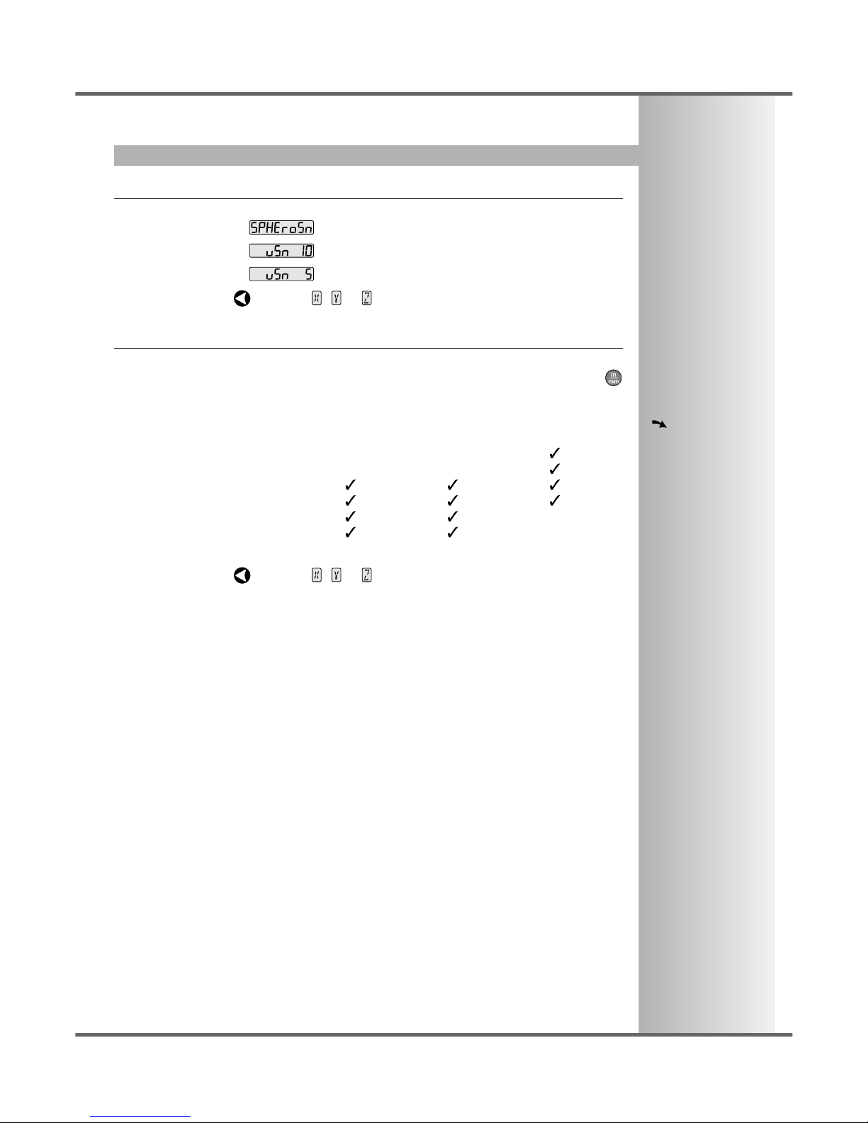
Segmented Error Compensation
In this mode, the scale travel for each axis can be broken down into as many as 99 user-defined
segments, with each segment having its own correction factor. The correction factors are calculated by
the C70 by comparison against known, user-supplied standards.
•When power is applied, the display for any axis that is set to use Segmented Compensation
shows .
•If the machine has not been moved since the power was turned off, simply press , and the C70
will restore the last positions recorded.
•Alternatively, set each axis close to the Reference Point - to within:
6.3mm (0.25”) for a Spherosyn encoder or
2.5mm (0.1”) for a Microsyn encoder,
and press the Select Key next to the , or . The C70 will re-establish alignment with the
correction parameters.
Linear Error Compensation
In this mode, a single constant correction factor for each axis can be applied to all displayed
measurements. The correction factor is calculated by the user, and specified in parts per million (ppm).
Values between -9999 and +9999 are allowed.
See pages 11 and 12 for details
on using Linear and Segmented
Error Compensation