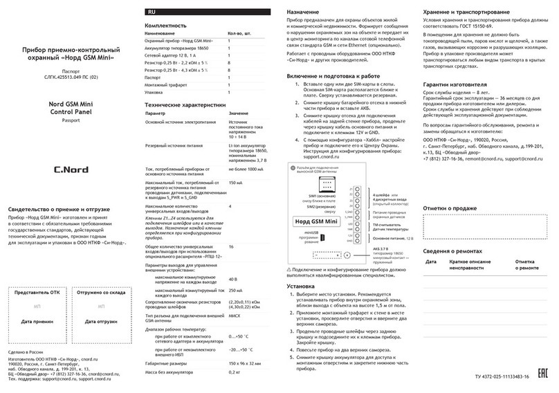
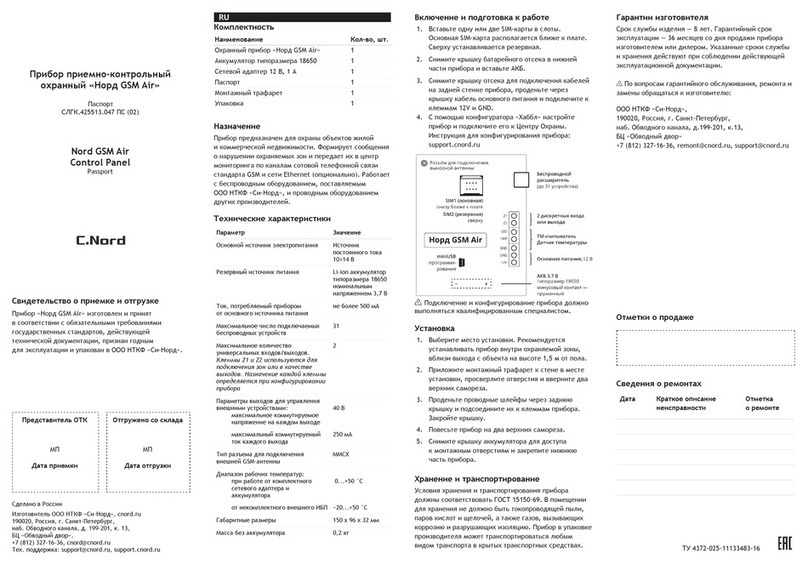
C.Nord GSM User manual

Nord GSM / Nord GSM WRL
Operation manual
October 12, 2018

Contents
1 Technical Description 5
1.1 Purpose and Capabilities .......................................... 5
1.2 Power Supply ................................................. 5
1.3 Notification Channels ............................................ 6
1.4 Functionality ................................................. 6
1.5 Main Technical Characteristics ....................................... 7
1.6 Scope of Delivery, Marking and Package .................................. 8
1.6.1 Scope of Delivery ........................................... 8
1.6.2 Marking ................................................ 9
1.6.3 Packing ................................................ 9
2 Device Control 10
2.1 TM-Key .................................................... 10
2.1.1 Reading Indication .......................................... 10
2.1.2 Error Indication ........................................... 10
2.1.3 Disarming Indication ......................................... 11
2.1.4 Arming Indication .......................................... 11
2.1.5 Standby Mode Indication ...................................... 11
2.2 K14-LED Keypad .............................................. 12
2.2.1 Getting Information about Site Status ............................... 13
2.2.2 Getting Information about Partition Status ............................ 13
2.2.3 Arming and Disarming ........................................ 13
2.2.4 Sound and Voice Indication ..................................... 15
2.2.5 Panic Button ............................................. 15
2.3 K16-LCD Keypad .............................................. 16
2.3.1 Arming and Disarming ........................................ 16
2.3.2 LED Indication ............................................ 17
2.3.3 Sound Indication ........................................... 18
2.3.4 Screen Indication ........................................... 18
2.4 CN-Keypad Wireless Keypad ........................................ 21
2.4.1 Arming and Disarming ........................................ 22
2.4.2 Getting Information about Status ................................. 23
2.4.3 Panic Button ............................................. 24
2.4.4 Backlight and Sound Turning Off .................................. 24
2.5 Wireless Keyfob ............................................... 24
2.5.1 MyAlarm Mobile Application .................................... 24
1

3 Installation and First Start 25
3.1 Device Wiring Diagram ........................................... 25
3.2 Connection of Wired Zones ......................................... 26
3.2.1 Normally Closed and Normally Open Zone ............................ 26
3.2.2 Terminating Resistors ........................................ 26
3.2.3 Zone without Terminating Resistors ................................ 26
3.2.4 Zone with One Terminating Resistor ................................ 27
3.2.5 Zone with Two Terminating Resistors ............................... 27
3.2.6 Wired Zones in Configurator .................................... 28
3.3 Connection of Fire Detectors ........................................ 29
3.3.1 Four-wire Fire Detectors ....................................... 29
3.3.2 Two-wire Fire Detectors ....................................... 29
3.4 Connection of Temperature Sensors ..................................... 30
3.5 Connection of Expander “EW-12” ..................................... 30
3.6 Connection of Expander “EW-8” ...................................... 34
3.7 GSM Channel Setting ............................................ 35
3.7.1 SIM Card Installation ........................................ 35
3.7.2 Check of GSM Signal Level ..................................... 36
3.7.3 Connection of Remote GSM Antenna ............................... 36
3.8 Connection of Touch Memory Reader ................................... 37
3.9 Connection of Wired Keypads ........................................ 37
4 Software Update 38
4.1 Device Connection to computer ....................................... 38
4.2 Driver Installation in Windows XP and Windows 7 ............................ 38
4.3 Driver Installation in Windows 8 ...................................... 43
4.4 Utility to update software .......................................... 46
5 Device Configuration 48
5.1 Control Panel and Tab Panel ........................................ 48
5.2 Control Panel ................................................. 48
5.2.1 Tab Panel ............................................... 50
5.3 Zones ..................................................... 51
5.3.1 Expanders ............................................... 51
5.3.2 Zones Numbering ........................................... 51
5.3.3 Turning Zone On and Off ...................................... 52
5.3.4 Zone Type .............................................. 52
5.3.5 Zone Normal State .......................................... 54
5.3.6 Terminating Resistors ........................................ 54
2

5.3.7 Entry Delay .............................................. 54
5.3.8 Exit Delay .............................................. 55
5.4 Wireless Devices ............................................... 56
5.4.1 Connection of New Device ...................................... 56
5.4.2 Repeater ............................................... 56
5.4.3 Assembly Instructions ........................................ 57
5.5 Users ...................................................... 58
5.6 Partitions ................................................... 60
5.6.1 Partition Management ........................................ 60
5.7 Miscellaneous ................................................. 61
5.7.1 Intervals ................................................ 61
5.7.2 Siren .................................................. 64
5.7.3 Backup Power Supply ........................................ 64
5.7.4 Arm and disarm ........................................... 65
5.7.5 Control and indication ........................................ 66
5.7.6 Configuration protection ....................................... 66
5.8 Security Center ................................................ 69
5.8.1 Device Identification ......................................... 69
5.8.2 GPRS Transmission Parameters .................................. 70
5.8.3 Transmission Parameters over Ethernet .............................. 71
5.8.4 Transmission Parameters in GSM CSD-Channel ......................... 72
5.8.5 Transmission Parameters via GSM voice channel ......................... 72
5.8.6 SMS Transmission Parameters ................................... 73
5.8.7 Communication Channel Switching ................................. 73
5.9 Radio ..................................................... 75
5.9.1 Radio channel settings ........................................ 75
5.9.2 Partition site numbers ........................................ 76
5.9.3 Device in metal case ......................................... 76
5.10 Cloud ..................................................... 77
5.11 Ethernet .................................................... 78
5.12 GSM operators ................................................ 79
5.13 Automatic controls .............................................. 80
5.13.1 Light indicator ............................................ 80
5.13.2 Siren .................................................. 82
5.13.3 Miscellaneous ............................................. 82
5.14 Event History ................................................. 85
5.15 State panel .................................................. 86
5.15.1 Communication channels ...................................... 86
5.15.2 Wired zones .............................................. 86
5.15.3 Wireless devices ........................................... 87
3

6 Remote Access to Device 88
6.1 Description of Remote Access Technology ................................. 88
6.1.1 Communication Channel Device → Receiver .......................... 88
6.1.2 Communication Channel Device → “Cloud” ........................... 89
6.1.3 Communication Channel Receiver → “Cloud” .......................... 89
6.2 Remote Access Setting ............................................ 89
6.2.1 Creating Engineer .......................................... 89
6.2.2 Granting Permissions to Engineer ................................. 91
6.3 Device Remote Configuration ........................................ 91
6.3.1 Selection of Site to Configure .................................... 91
6.3.2 Working with Configuration ..................................... 92
6.3.3 Work Features ............................................ 93
6.4 Remote Software Update on Device ..................................... 93
6.4.1 Information about Sites on Receiver ................................ 93
6.4.2 Process of Remote Software Update on Device .......................... 94
6.4.3 Updating Software on Selected Site ................................. 95
6.4.4 Updating Software on all Sites ................................... 95
6.4.5 Update Process Stopping ...................................... 96
7 Event codes 97
4

1 Technical Description
1.1 Purpose and Capabilities
The “Nord GSM” device is intended for operation as the head unit of the security and fire complex - the receiving
and monitoring security and fire alarm device (PKKOP), installed in the premises at the protected sites.
Various wired and wireless security, fire and process detectors and devices can be connected to the device. An
optional CN-WRL wireless expander is used to connect wireless devices.
The device can generate and transmit to the control panel messages about events occurring during its operation
and related to:
∙the device arming or disarming;
∙changes in the state of its security zones;
∙changes in the state of its power sources (main and backup);
∙disruptions in the operation of communication channels used by the product and other malfunctions;
∙activation and restoration of the state of the housing tamper switch.
The device transmits notifications to the receiver using the built-in GSM/GPRS-communicator via voice channel,
SMS or GPRS. It is possible to transmit messages over the Ethernet network using the optional Ethernet Adapter
module installed in the product, as well as via the radio channel using the midrange, VHF or UHF radio transmitter
installed in the product.
The device is equipped with uninterrupted power supply and automatically maintains its backup power source
installed in its case during its entire operating life. The product is capable of providing power supply to the
connected communication modules (communicators) and devices for expanding its functionality within the limits
of permissible consumed capacities.
1.2 Power Supply
The main power source of the product is a single-phase network AC 220 V 50 Hz with a high voltage of (127÷264)V.
The following can be used as a backup power source:
∙sealed lead-acid battery (battery), corresponding to the standard IEC 1056-1, with a rated voltage of
(12.6±0.6) V. The battery is installed inside the product body;
∙external uninterruptible power supply (UPS), with a rated nominal output voltage of 12 V and permissible
current load of at least 1.5 A with the installed battery of the required chemical system. The external UPS
shall be connected to the product instead of the battery.
The permissible voltage range of the backup source when the product is started in the absence of the main source
is from 10.0 V to 14.4 V.
The recommended capacity of the battery installed inside the product plastic case is 1.2 or 2.2 (Ah), for example,
DELTA DTM 12022.
The product provides automatic maintenance of the installed battery, which includes the following:
∙stage of a “sparing” charge of a deeply discharged battery with a current of (100±20) mA before reaching the
voltage of (11.5±0.2) V;
∙subsequent charge of the battery at the second stage with a current of (230±25) mA;
∙final voltage on the battery at the end of its charging cycle at (14.0±0.2) V and then keeping it in the range
of (13.6÷14.0) V to compensate the current of its self-discharge;
∙ability to automatically turn off the discharged battery in the absence of the main power supply when the
voltage on it reaches (9.0±0.3) V;
5

∙25 mA limitation of the current consumed by the product from the automatically disconnected battery;
∙stability to both the break and short circuit in the battery circuit is unlimited in time, while the product will
be powered from the main source;
∙protection against “reverse polarity” in case of wrong connection to the battery terminals or external UPS;
∙automatic periodic testing of the battery and evaluation of its state by several parameters with subsequent
sending of the corresponding notices to the panel program. The option can be disabled while configuring the
product;
∙automatic “training” of the battery by periodic short-term sampling of the current pulse into the low-resistance
load built into the product. This procedure implements the charge algorithm with an asymmetric current
with alternating signs current that favorably affects both the completeness of the charge and the lifetime of
the battery operated in the buffer mode. The option can be disabled while configuring the product.
If an external UPS is used as a backup power source, the product continues to periodically monitor the fact of its
connection, but does not monitor the following:
∙charge of an external source;
∙its periodic testing with an evaluation of the current charge level and value of internal resistance.
1.3 Notification Channels
The product notifications can be sent by the following independent communication channels:
∙via GSM 900/1800 cellular networks of two different carriers through the built-in GSM-modem;
∙via Ethernet network using the optional “Ethernet Adapter” module, which is installed in the product and
connected to the dedicated socket of the product main board;
∙via the radio channel in the midband, VHF, UHF bands with the help of an optional radio transmitter
connected to the interface connector “TR-100 OUT” of the product (for the product in a metal case).
The product in a plastic case is equipped with a small GSM stub antenna without a feeder with an angular connector
of SMA-male type, connected to the connector type of SMA-female type. For products in a plastic case, it is possible
to connect a remote dipole antenna (with a connector of the same type) to improve the communication quality with
the base station of the carrier. The product in a metal case is equipped exclusively with a remote dipole antenna.
To transmit events to the monitoring panel, the device can use the following communication channels:
∙GPRS;
∙CSD (for devices of hardware version 5.1, 5.2, 5.7);
∙VOICE (voice channel with DTMF-encoding);
∙SMS.
In the mode of packet transmission of notifications (GPRS), the content is encrypted.
The device has a two-tier SIM-card holder, in which it is possible to install two SIMs of different carriers. The
active SIM is selected automatically, in accordance with the established algorithm of the cellular communication
module. In addition, there is an unconditional transfer to another SIM when the user presses a button installed
next to the SIM holder.
The device can estimate the signal level in the carrier networks at the device installation site separately for each of
the two SIMs and display the received result in the configurator interface.
1.4 Functionality
∙configuration of up to 16 alarm wired zones intended for receiving notifications from analogue manual and
automatic security and fire detectors, security and fire alarm system units through the outputs of the central
security panel relays;
6

∙connection of up to 31 wireless devices;
∙configuration of up to 32 partitions with the possibility of their independent arming and disarming.
∙control of actuators and automation facilities using open-collector control outputs;
∙control of the product operation mode using wired keypads K16-LCD, K14-LED, wireless keypad CN-Keypad,
electronic keys Touch Memory, proximity card reader, and wireless keyfobs;
∙sound and light alarm in “Alarm” and “Fire” modes;
∙control of the product case opening;
∙control of the zone operability with automatic detection of an open or short circuit, light and sound alarm
signaling, formation of notifications for the receiver about the fault;
∙sound and light indication when the product is armed and disarmed;
∙storing of information to the event log.
1.5 Main Technical Characteristics
∙The minimum number of the product wired security zones, designed to connect different detectors, is 8;
∙The number of the product security zones, when the product is equipped with an expander for the number of
wired zones, is 16;
∙The maximum allowable total resistance of two wires of each zone - no more than 330 Om;
∙The number of wireless (stand-alone) terminal units supported by the product when installing the radio
channel signaling zone extension unit CN-WRL is up to 31;
∙For joint operation with the product in the version of the “Nord GSM/WRL” (with the installed radio
expander CN-WRL), the following radio channel terminal units can be used:
–manual security detector ≪CN-KeyFob≫;
–volume electro-optical security detector ≪CN-PIR≫;
–volume electro-optical street security detector ≪CN-PIR-Outdoor≫;
–manual security detector magnetic contact ≪CN-Magnetic≫;
–surface sound security detector ≪CN-Glass≫;
–fire detector ≪CN-Smoke≫;
–manual fire detector ≪CN-Fire≫;
–flooding detector ≪CN-Flood≫;
–temperature detector ≪CN-Celsius≫;
–notification repeater ≪CN-Repeater≫;
–siren ≪CN-Siren≫;
–keypad “CN-Keypad”.
The optional radio expander CN-WRL is connected to the product main board by means of a special
4-pin connector via RS-232 v.24 interface (with TTL logic signal levels), and the radio extender is
powered through the same connector.
∙The maximum number of wired zone states controlled by the product is four (“norm”, “alarm”, “break”,
“closing”). In this case, the type of each of the organized zones is normally closed or normally open, as well as
the number of termination resistors, with one or two termination resistors - is set by the user when configuring
the product;
∙The product allows connection of four-wire fire sensors to the security wired zones, providing the possibility
of their automatic restart (alarm reset) by switching in their power lines.
∙The maximum current consumption of all wired sensors connected to the product is limited by the value of
self recovering thermal switch and shall not exceed 200 mA;
∙The product is equipped with a microswitch installed on its board, which acts as a tamper switch.
In addition, it is possible to install a terminal block on the board to connect an external tamper
switch (for the product version in a metal case);
7

∙The product has non-volatile memory for storing messages generated by it;
∙The product provides support for the 1-Wire protocol in the rank of “master” on the connector of the
corresponding interface, allowing its arming and disarming, for example, with the help of devices of the
DS1990A series, connecting remote temperature sensors, hardware devices for expanding the controller ports,
etc. (support of different device on the 1-Wire bus is determined by the software version of the product
controller). The “LED” line of the 1-Wire interface is short-circuit protected and is designed to connect an
external LED indicating the product status, with a current consumption of up to 8 mA (for example, LED
located in the TM reader);
∙The product is equipped with terminals for connecting K16-LCD and K14-LED wired keypads. The power
lines of the keypad interface are short-circuit protected by a self recovering thermal switch, the absence or
violation of traffic in the keypad interface is detected by the product controller;
∙A piezoelectric siren can be connected to the product for sound confirmation of the “Alarm” state with a
current consumption up to 200 mA, at the same time the product detects such malfunctions in its connection
circuit as a break and short circuit, both in the absence and in the presence of “Alarm” signal. The output
for the siren connection is protected by the self recovering thermal switch;
∙The product has seven controlled discrete outputs of “open collector” type, allowing connecting the switched
load to the product, for example, electromagnetic relays, acoustic or electrooptical devices. The maximum
allowable sink load current of discrete outputs is 500 mA; the maximum permissible DC voltage supplied to
the outputs is plus 50 V;
∙The main board is equipped with a multifunctional three-color process LED designed to display the current
state of the product and the estimated values of some of the parameters monitored by it;
∙The product provides voice support to the user (maintenance staff) by playing audio files through the built-
in speaker if problems are detected that prevent the normal operation of the product, for example, when
troubleshooting security zones with the specification of the failure nature and location, reaching a negative
balance of the bill for security services, etc.
∙The product is equipped with a vertical connector of the “mini USB B” type for its configuration after
connecting to the computer USB port;
∙By means of special software it is possible to remotely change the product configuration parameters, as well
as update the controller software;
∙The product is designed for continuous (twenty-four-hour) operation in the operating temperature range
(without taking into account the temperature limitations of the backup power supply) from -30∘C to +50∘C;
The permissible product operating temperature range with a backup source is determined by the
characteristics of the battery installed in it, and first of all by the maximum permissible temperature
values during charging.
∙Overall dimensions of the plastic case, mm, maximum, - 188x200x62;
∙The product weight in a plastic case (without a backup power source, power cord and packaging), kg, maxi-
mum, - 0,6;
1.6 Scope of Delivery, Marking and Package
1.6.1 Scope of Delivery
Receiving and monitoring security and fire alarm device “Nord GSM”/“Nord GSM WRL” 1 pcs.
Output resistor 0.25 W (0.16 W) - 2.2 kOm 16 pcs.
Output resistor 0.25 W (0.16 W) - 4.3 kOm 16 pcs.
Fuse link VPB6-7, 1 A, 250 V 1 pc.
8

Plastic battery retainer with a capacity of 1.2 Ah in the product case 1 pc.
Grounding set ZK-15 (m) 1 pc.
Set of fasteners (m) 1 pc.
Remote GSM antenna 2J520-SMA-male (or similar) (m) 1 pc.
Certificate 1 pc.
Packing 1 pc.
Note: (m) - for the product in a metal case
1.6.2 Marking
The product printed circuit board has a marking indicating the polarity of the terminals of the terminal blocks and
their purpose.
The product is marked in the form of labels with the name of the product and bar code. The labels are glued on the
front side of the product printed circuit board and case. In addition, the label is glued in the product certificate.
1.6.3 Packing
The product is delivered in a separate cardboard box. Before placing in a box, the product in a plastic case is
packed in a polyethylene air-bubble bag, providing the product additional protection from damage and increased
humidity during storage and transportation. The accessories are shipped with the product in accordance with the
scope of delivery.
9

2 Device Control
The following control devices can be used to for the device arming/disarming:
∙TM-key;
∙keypad K14-LED;
∙keypad K16-LCD;
∙wireless keyfob CN-Keyfob;
∙mobile application MyAlarm.
2.1 TM-Key
Figure 1: TM-reader and TM-key
The device has a built-in interface for connecting the TM-key readers. In addition, the device provides the ability
to connect the LED indicator, which is located directly in the case of some models of TM-key readers.
The LED indicator located in the TM-reader case is intended for indication of the TM-key reading, arming and
disarming, and also for indicating the device current state.
With a single TM-key it is possible to arm or disarm one partition. If one user has to be able to arm or disarm
several partitions at the same time, then the appropriate rules shall be set in the “Automatic controls” section.
2.1.1 Reading Indication
If the key reading operation has completed successfully, the device indicates this fact, regardless of whether the key
is found in the device memory or not. In other words, if the reading is successful, the device simply confirms that
a key has been brought to the reader and this key has been read.
Indication of successful reading of the TM-key: the LED “flashes” (turns on for 0.1 sec., then turns off for 0.1 sec.)
for 1 second.
2.1.2 Error Indication
The following errors are possible during a key reading:
∙key is not found in the device memory;
∙arming rejection.
Error indication: the LED “flashes” (turns on for 0.5 s, then turns off for 0.5 s.) for 3 seconds.
10

2.1.3 Disarming Indication
If the key, with which you can change the partition status and this partition is armed, is read, then the partition
is disarmed.
The disarming is indicated after the reading is completed.
Disarming indication: the LED turns on for 5 seconds and turns off.
After the disarming indication is displayed, the standby mode indicator is enabled.
2.1.4 Arming Indication
If a key, with which it is possible to change the partition status, is read, then if there are no zones in the partition
with exit delay, the partition is armed. If there are zones with exit delay, then the delay interval counting starts;
arming is performed after the exit delay expires.
The arming indication depends on how many partitions are configured in the device.
One Partition
If only one partition is configured in the device, then after it has been armed, the LED turns on and remains lit:
the standby mode indicator with the only partition armed is enabled.
Several Partitions
If several partitions are configured in the device, then the indication after the current one is armed depends on
whether the disarmed partitions remained or not.
If all partitions are armed, the LED turns on and remains lit: the standby mode indicator with several partitions
is activated, all partitions are armed.
If there is at least one not armed partition, the LED turns on and is glowing for 20 seconds. After that, the
indication of the standby mode with several partitions is enabled, some of which are disarmed.
Arming Rejection
“Arming rejection” is the impossibility to arm the site, if the security alarm on the site is faulty, or arming is
prohibited due to lack of payment for security services.
There are the following reasons for arming rejection:
∙malfunction of one or more zones;
∙alarm in one or more zones;
∙no communication with the panel program via IP channel;
∙absence of 220V on the site;
∙no payment for security services;
∙the device case is opened.
2.1.5 Standby Mode Indication
At the time of the reading indication, arming/disarming errors, arming and disarming the indication of the standby
mode is interrupted.
The standby mode indication depends on how many partitions are configured in the device.
11

One Partition
If only one partition is configured in the device, then the LED indicates the partition status, the presence of an
alarm during protection and faulty zones:
∙LED is on continuously if the partition is armed;
∙LED is not on if the partition is disarmed;
∙the LED “flashes” (blink), if there are faults in the zones;
∙the LED “flashes”, if after the partition was armed, there was an alarm and the partition was not disarmed.
“Flashing” means that the LED turns on for 1 second, then turns off for 1 second, then turns on again
for 1 second, etc.
Several Partitions
If several partitions are configured in the device, then only the following is indicated: the entire device arming,
presence of an alarm, when the entire device was under protection, and also the zone faults.
∙LED is on continuously if all device partitions are armed;
∙LED is off if at least one of the partitions is disarmed;
∙LED “flashes” if there are faults in the zones;
∙LED “flashes”, if after the device was armed, there was an alarm and the alarmed partition was not disarmed.
2.2 K14-LED Keypad
Figure 2: K14-LED keypad
12

Using the K14-LED keypad, the user can perform the following tasks:
∙check the partition status (armed/disarmed);
∙arm or disarm a partition;
∙check about the beginning or active exit or entry delay;
∙check the protection state of the entire device;
The K14-LED keypad has green and red LEDs:
∙the red LED is on continuously if all device partitions are armed;
∙if the partition is disarmed, the red LED goes out and the green LED is lit.
∙Red and green LEDs flash simultaneously if an error occurs. For example, if an incorrect user code is entered
or in case of arming rejection.
2.2.1 Getting Information about Site Status
To get information about a site status press ibutton:
∙if the partitions are configured on the device and all partitions are armed, the keypad will say: “Site is armed”
and the red LED will turn on.
∙if the partitions are configured on the device and all partitions are disarmed, the keypad will say: “Site is
disarmed” and the green LED will turn on.
∙if the partitions are configured on the device and some of them are armed and others are disarmed, the keypad
displays an error indication.
∙if the partitions are not configured on the device, the keypad displays an error indication.
2.2.2 Getting Information about Partition Status
To get information about a partition status press the partition number button and ibutton:
∙if the partition exists, the keypad says its state and turns on the corresponding LED.
∙if the partition does not exist, the keypad displays an error indication.
2.2.3 Arming and Disarming
The device has the ability to arm and disarm several partitions with one user code. The partitions that can be
armed or disarmed with a specific code are configured during the device configuration.
Arming
To arm a partition, it is necessary to press the “house” icon and enter the user code.
∙if the code is correct, then the site (partition) will be armed, the keypad will confirm the arming by turning
on the red LED. Or the countdown of the exit delay will start, which will be accompanied by a sound and
LED indication.
∙if the code is incorrect or the user who owns this code has more than one partition, the keypad will display
an error.
∙if arming is not possible, the keypad will display an error.
13

Figure 3
If several partitions are assigned to the user code, then first the user shall click the “house” button, select the
partition, which state he/she wants to change, and then type the code.
Figure 4: Example of partition arming
Arming Rejection
“Arming rejection” is the impossibility to arm the site, if the security alarm on the site is faulty, or arming is
prohibited due to lack of payment for security services.
There are the following reasons for arming rejection:
∙malfunction of one or more zones;
∙alarm in one or more zones;
∙no communication with the panel program via IP channel;
∙absence of 220V on the site;
∙no payment for security services;
∙the device case is opened.
Disarming
If the user can control only one partition, to disarm it is necessary to enter the user code.
∙if the code is correct, then the site (partition) will be disarmed. The keypad will confirm disarming by turning
on the green LED;
∙if the code is incorrect or the user, who owns this code, can control several partitions, the keypad will display
an error.
Figure 5
If the user can control several partitions, to disarm them, it is necessary to type the partition number, then # and
enter the user code.
∙If the code is correct, then the partition will be disarmed. The keypad will confirm disarming by turning on
the green LED.
∙In case of repeated disarming of the same partition, the keypad will display its status: the green LED will
turn on.
Figure 6: Example of disarming with partition selection
The exit or entry delay countdown is indicated by the intermittent sound, which is reproduced during the entire
delay interval. The sound indication of the exit or entry delay is disabled when any button on the keypad is pressed.
14

2.2.4 Sound and Voice Indication
The keypad has a built-in speaker, through which the voice indication and beep indication are made. Pressing the
buttons on the keypad is accompanied by a beep that confirms the press.
The voice indicates the following:
∙Arming and disarming of the partitions and the entire site;
∙Arming rejections;
∙Warnings about receivables during arming;
∙The status of the partition or the entire site (when the i key is pressed).
The keypad has a volume control for the built-in speaker. The Adjustment is five-step - from the state “off” to the
volume levels from the first to the fourth. The volume level can be selected by pressing the “#” and “9” keys.
2.2.5 Panic Button
If the device configuration permits the use of the keypad as a panic button, then for activation it is necessary to
press and hold the “houses” button for 3 seconds. The panic button pressing is confirmed by turning on of green
and red LEDs for 1 second accompanied by sound.
If the device configuration prohibits the use of the keypad as a panic button, then the keypad will display an error.
15

2.3 K16-LCD Keypad
Figure 7: K16-LCD Keypad
Using the K16-LCD keypad, the user can perform the following tasks:
∙check the partition status (armed/disarmed);
∙arm or disarm a partition;
∙check about the beginning or active exit or entry delay;
∙check the entire device status;
∙find out if there is a power failure of the device;
∙find out about the presence of faults.
2.3.1 Arming and Disarming
The device has the ability to arm and disarm several partitions with one user code. The partitions that can be
armed or disarmed with a specific code are configured during the device configuration.
Arming and Disarming without Partition Selection
If only one partition is assigned to the user code, then when typing the code, an attempt will be made to change
the security status of this partition:
∙if the partition is armed, then when the code is being typed, it will be disarmed;
∙if the partition is disarmed, the procedure for the partition arming will begin when the code is being typed.
16

If arming is enabled, then arming is performed, or the exit delay interval is started, which is accompanied by a
sound, LED and screen indication.
If arming is prohibited, then a sound indication of the rejection is made, and the reason for which the arming is
impossible is displayed on the keypad screen.
Arming and Disarming with Partition Selection
If several partitions are assigned to the user code, then first the user shall select the partition, which state he/she
wants to change, and then type the code.
To select a partition, the user shall first enter the number of the partition, which state he/she wants to change, and
then click the “#” button.
Let’s suppose that the user wants to disarm partition number 2 using the code 1234. To do this, he/she
shall press the following sequence of buttons on the keypad: 2 # 1234
If the user types the correct code with several partitions assigned, but previously he/she has not selected the
partition, which state shall be changed, then such code is treated as incorrect.
Arming Rejection
“Arming rejection” is the impossibility to arm the site, if the security alarm on the site is faulty, or arming is
prohibited due to lack of payment for security services.
There are the following reasons for arming rejection:
∙malfunction of one or more zones;
∙alarm in one or more zones;
∙no communication with the panel program via IP channel;
∙absence of 220V on the site;
∙no payment for security services;
∙the device case is opened.
2.3.2 LED Indication
There are two LEDs on the K16-LCD keypad: “Emergency” and “Arm”.
“Arm” LED
The LED has two display modes: standby mode and arming mode.
In standby mode, the “Arm” LED displays the status of the entire device:
∙if only one partition is configured for the device, the LED is on, if this partition is armed, and turned off if
disarmed;
∙if several partitions are configured for the device, the LED is on, if all partitions are armed, and turned off if
at least one partition is disarmed;
∙if none of the conditions described above are met, then the LED is off.
In the arming mode, the LED “flashes rapidly” during the exit delay.
17

”Emergency” LED
The LED is intended to indicate the absence of main power, as well as a malfunction of the backup power source:
∙the LED is on if the main power is present and the backup power source is missing, discharged or defective;
∙the LED “flashes slowly”, if there is no main power;
∙the LED is off if main power is present, and there are no backup power failures.
The failure of the backup power source is indicated only if the battery is indicated as the backup power
source in the device settings, and the backup power quality control is switched on.
2.3.3 Sound Indication
Pressing the buttons on the keypad is accompanied by a beep that confirms the press.
The exit or entry delay countdown is indicated by the intermittent sound, which is reproduced during the entire
delay interval. The sound indication of the exit or entry delay is disabled when any button on the keypad is pressed.
Unlike the “Arm” LED, which indicates only the exit delay, the sound annunciator built into the K16-
LCD keypad indicates both the exit and entry delay.
2.3.4 Screen Indication
The K16-LCD keypad is equipped with a two-line liquid crystal display, each line of which can display up to 16
alphanumeric characters.
The information displayed on the K16-LCD keypad screen depends on the current status of the device, as well as
on operations performed by the user.
Standby indication - the device is completely disarmed
If all partitions of the device are disarmed and users do not perform any operations with the keypad, the keypad
screen displays the current date and time, as well as information about the current faults of the device, if any.
Information about the current date and time is displayed on the first line of the screen.
The information on the faults is displayed on the second line of the screen.
Example of the keypad screen when the device is completely disarmed:
12.02.2015 10:25
220V NOT CONNECTED
If there are several faults in the device, only the one of the highest priority is displayed on the keypad screen.
List of faults (listed in order of priority during display):
Fault Description
PAY FOR SECURITY! The line is displayed if one of the values in the site settings that are performed in
the Security Center software is intended to inform the user of the control panel
of the need to pay for security services.
220V NOT CONNECTED The line is displayed if there is no main power on the device. When configuring
the device, the device may not be allowed to arm when there is no main power.
NO IP CONNECTION The string is displayed if there is no IP connection (over Ethernet or GPRS) with
the Security Center. When configuring the device, the device may not be allowed
to arm when there is no IP connection with the Security Center.
18

OPEN CASE! The line is displayed if the device case is open.
NN ZONE FAULT The line is displayed if a fault is detected in the wired or wireless zone connected
to the device: an open or short circuit in the zone, no communication with the
wireless device, discharged power supply of the wireless device, etc.
BATTERY IS NOT CONNECTED The line is displayed if the backup power source is not connected to the device.
BATTERY IS DISCHARGED The line is displayed if the voltage measured on the terminals for connecting the
backup power source indicates that the backup power source is empty.
Standby indication - the device is partially armed
If some part of the device is armed and another part is disarmed and the user does not perform any operations
with the keypad, the current time and a list of armed partitions is displayed on the keypad screen.
Information about armed partitions and current time are displayed in the first screen line.
The list of the armed partition numbers is displayed in the second screen line.
Example of the keypad screen when the device is partially armed:
ARMED 10:25
PARTITIONS 1,4,5
Standby indication - the device is fully armed
If the device is fully armed and the user does not perform any operations with the keypad, the current time
information that the device is fully armed are displayed on the keypad screen.
Example of the keypad screen when the device is fully armed:
ARMED 10:25
ALL PARTITIONS
If only one partition is configured for the device, then when it is armed, the line ≪ALL PARTITIONS≫is
not displayed.
Arming Indication
If the arming is allowed and there is no exit delay, the phrase ≪ARMING...≫is displayed on the first line of the
keypad screen for 3 seconds, after which the keypad screen switches to the standby mode corresponding to the
device security state.
If there is an exit delay, then during the exit delay , the phrase ≪ARMING...NN≫is displayed in the first line of the
keypad screen, where NN is the time in seconds of the exit delay. Information about the time, during which the
exit delay will continue, is updated every second.
The LED, sound and screen indication of the exit delay is disabled when any button on the keypad is
pressed.
If according to the site settings in the Security Center software the user shall be informed about the need to pay
for security services during arming and disarming, the second line of the keypad screen displays the phrase ≪PAY
FOR SECURITY!≫.
Example of a keypad screen with arming indication:
ARMING... 18
PAY FOR SECURITY!
19
Other manuals for GSM
1
This manual suits for next models
1
Table of contents
Other C.Nord Control Panel manuals
