C.P.A. White Pool 490 Quick guide

WHITE POOL INSTRUCTION MANUAL pag. 1 / 29
www.cpa-piscine.it
Rev.00–16/10/20
C.P.A. S.R.L.
WHITE POOL
Assembly and maintenance guide
READ CAREFULLY THIS MANUAL AND RETAIN FOR LATER REFERENCE

WHITE POOL INSTRUCTION MANUAL pag. 2 / 29
www.cpa-piscine.it
Rev.00–16/10/20
Summary
IMPORTANT SAFETY INSTRUCTIONS .............................................................................................................3
COMPONENTS...........................................................................................................................................5
PHASE 1 –Selecting a suitable site................................................................................................................7
PHASE 2 –Pool setup.................................................................................................................................8
I. Ground preparation.......................................................................................................................8
II. Marking the site............................................................................................................................9
III. Levelling the area ........................................................................................................................10
IV. Pool frame assembly....................................................................................................................11
V. Installing assembled frames ..........................................................................................................16
VI.Assembling the pool base rails.......................................................................................................18
VII. Fine adjustment of the bottom rails diameter...................................................................................19
VIII. Fixing the pool wall......................................................................................................................20
IX. Measuring the pool wall ...............................................................................................................21
X. Making a protective sand cushion at the foot of the inner pool............................................................22
XI. Fitting the PVC pool liner ..............................................................................................................22
XII. Assembly of the resin vertical supports ...........................................................................................24
XIII. Assembly of the joint protectors ....................................................................................................26
XIV. Check all connections and joins......................................................................................................27
XV. Fixing the leaf skimmer ................................................................................................................28
PHASE 3 –Filling the pool with water..........................................................................................................28
PHASE 4 –Pool maintenance.....................................................................................................................29

WHITE POOL INSTRUCTION MANUAL pag. 3 / 29
www.cpa-piscine.it
Rev.00–16/10/20
IMPORTANT SAFETY INSTRUCTIONS
The following instructions contain important safety information, we strongly encourage you to read these important safety
instructions and abide by them when using this pool. When installing and using this electrical equipment, basic safety precautions
should always be followed, this includes the following.
Read and follow all these instructions
Note - Please examine equipment before use. If there are any damaged or missing parts at the time of purchase, do not assemble
or operate until parts are replaced.
Warning - Consult your local council, state government or water authority in regards to the use of water and / or water restrictions
relating to this product.
Warning - Water attracts children; always remove pool ladder when not in use. Store in a place not accessible to children.
Danger - Prevent the risk of accidental drowning. Extreme caution must be exercised to prevent unauthorized access by children.
To avoid accidents, ensure that children can not use the pool unless they are supervised by an adult at all times.
NEVER LEAVE CHILDREN UNATTENDED.
Warning - Risk of electric shock. Connect filter pump only to a grounding type receptacle protected by an RCD (Residual Current
Device). Use a qualified electrician to install the RCD, which has a maximum rate of 30mA.
Warning - Know where the cut-off switch for your pump is at all times, so you can turn it off in an emergency. It is necessary to
have the RCD (Residual Current Devise) cut-off switch plug accessible after installation of the pool.
Warning - Never use an extension cord to connect the filter pump to a power source. Doing so could cause damage to the filter
pump system.
WHITE POOL INSTRUCTION MANUAL pag. 4 / 29
www.cpa-piscine.it
Rev.00–16/10/20
Follow these safety rules:
Warning - To avoid electrocution, do not permit electric devices i.e. light, telephone, radio, television, hair dryer, etc. within 2,5
m (8 ft) of this pool.
Warning - Risk of electric shock. Never operate any electrical appliance when in the pool or when your body is wet.
Warning - Warning - to reduce the risk of injury or hazard, have any damaged cord replaced immediately by the manufacturer, its
service agent, or similarly qualified persons.
Warning - Do not burry electric cord. Avoid using lawn mowers, hedge trimmers and other garden equipment near or around the
metal wall pool and electrical cord.
Warning - Never swim or bathe in the pool during rain or an electrical storm or if there is a threat of lightning in the vicinity of the
pool.
Warning - Never allow horseplay, diving or jumping into or around the metal wall pool. Never enter the pool via any desks or other
raised surfaces; the water level of the pool is shallow. Serious injury, paralysis or death could result.
Caution - It is advisable to wear protective gloves when assembling pool
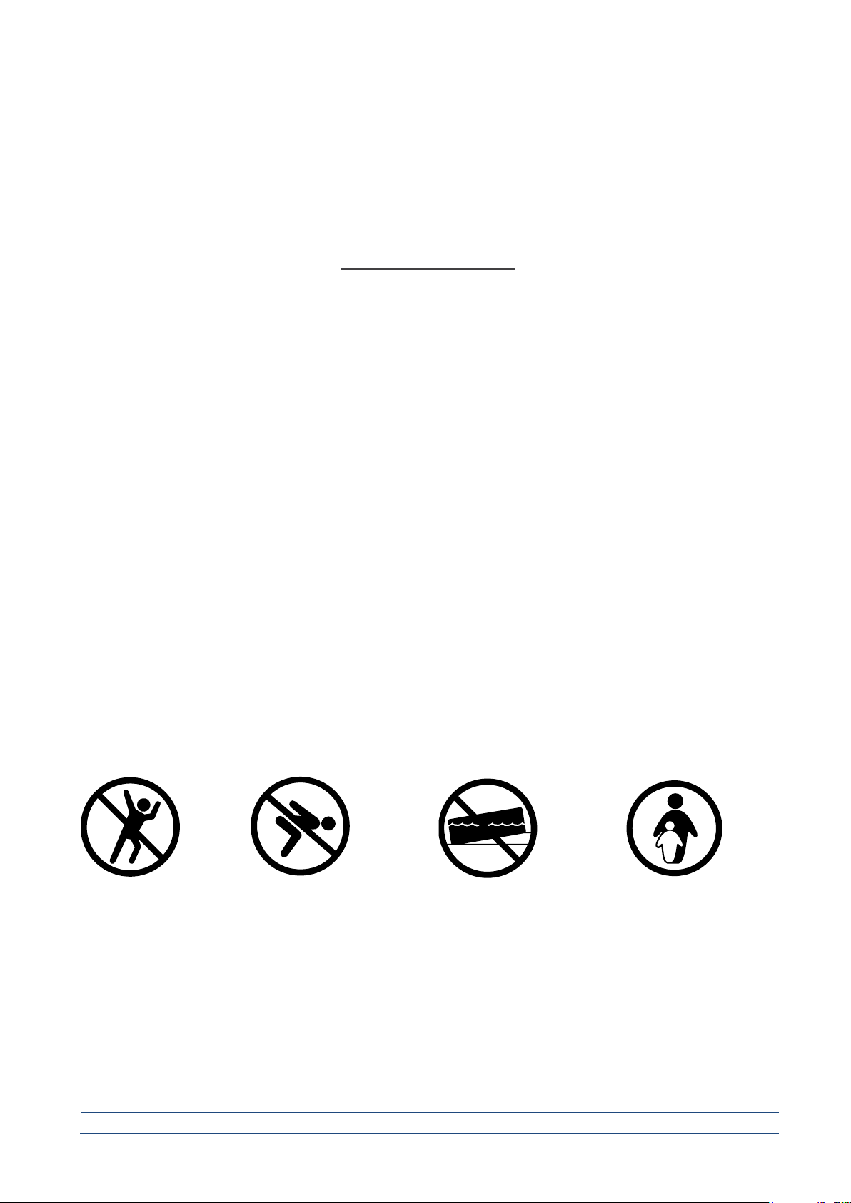
No diving
No jumping
No sloping ground
Use only under competent supervision
Save these instructions
WHITE POOL INSTRUCTION MANUAL pag. 5 / 29
www.cpa-piscine.it
Rev.00–16/10/20
5 6 7
8
9
10
11
12
13
14
15
21
22
23
16
17
18
19
24
25
26
27
28
20
12
3
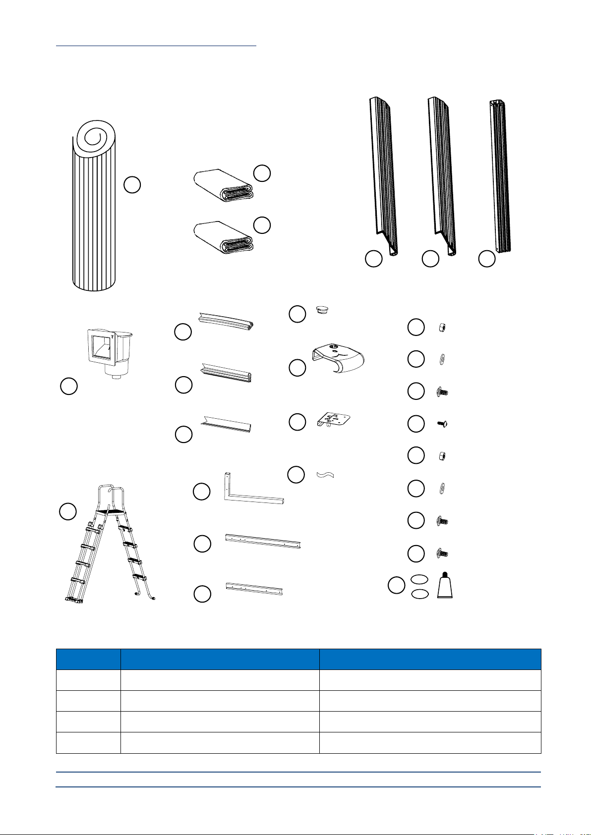
pool wall
leaf skimmer
ladder
pool liner
ground sheet
top platform side top
platform
A and B
vertical
support
N.B. for parts list please
refer to the skimmer box
manual.
bottom rail
fix rail
round rail
protector plug
upper joint
protector
top/bottom
metal piece
adhesive tape
nut M6
washer M6
bolt M6 x 11
bolt M4 x 10
nut M12
washer M12
bolt M12 x 24
bolt M12 x 100
maintenance kit
L support
fixing plate
connection plate
Components
Item No.
Description
Pool dimension (mm)
8011015
White Pool 490
L4900 x W3600 x H1300
8011012
White Pool 610
L6100 x W3600 x H1300
8011013
White Pool 730
L7300 x W3600 x H1300
8011014
White Pool 910
L9100 x W4600 x H1300

WHITE POOL INSTRUCTION MANUAL pag. 6 / 29
www.cpa-piscine.it
Rev.00–16/10/20
No.
Description
white pool 490
8011012
white pool 610
8011012
white pool 730
8011013
white pool 910
8011014
1
Pool wall
1
1
1
1
2
Pool liner
1
1
1
1
3
Ground sheet
1
1
1
1
5
Top platform
1370mm length
10
10
10
0
Top platform
1460mm length
0
0
0
12
6
Side top platform
1210mm length
0
2
4
0
Side top platform
1445mm length
0
0
0
4
7
Pool wall vertical support
10
12
14
16
8
Leaf skimmer
1
1
1
1
9
Bottom rail
1350mm length
10
10
10
0
Bottom rail
1245mm length
0
2
4
0
Bottom rail
1445mm length
0
0
0
16
10
Fix rail
1380mm length
11
11
11
0
Fix rail
1270mm length
0
2
4
0
Fix rail
1460mm length
0
0
0
17
11
Round rail
1380mm length
11
11
11
0
Round rail
1270mm length
0
2
4
0
Round rail
1460mm length
0
0
0
17
12
Protector plug
10
12
14
16
13
Upper joint protector
10
12
14
16
14
Top/bottom metal piece
18
20
22
26
15
Self-adhesive tape
1
1
1
1
16
M6 - nut
29
29
29
29
17
M6 - washer
29
29
29
29
18
M6x11 - bolt
83
97
111
121
19
M4x10 - bolt
54
80
66
78
20
ladder
1
1
1
1
21
L support
2
4
6
6
22
Fixing plate
1415mm length
2
4
6
0
Fixing plate
1714mm length
0
0
0
6
23
Connection plate
1270mm length
1
2
3
0
Connection plate
1620mm length
0
0
0
3
24
M12 - nut
8
16
24
24
25
M12 - washer
8
16
24
24
26
M12x24 - bolt
4
8
12
12
27
M12x100 - bolt
4
8
12
12
28
Maintenance kit
1
1
1
1
WHITE POOL INSTRUCTION MANUAL pag. 7 / 29
www.cpa-piscine.it
Rev.00–16/10/20
PHASE 1 –Selecting a suitable site
Carefully select the site for your new pool. This is the most important decision you will have to make to ensure the safety
and success of your pool construction. An incorrect site could cause problems in the future that may cause in jury, death or
financial loss.
Read carefully the check list set out below when selecting your site.
TOOLS REQUIRED
•Phillips head screw driver
•Small shifter
•Clothes pegs
•Sharp knife
•Spirit level
•Site excavation tools
•Protective gloves
•Pre-cast cement block
ACCEPTABLE
Flat, level, firm and dry ground with easy access to all sides of the pool exposed to direct sunlight, preferably in the morning.
Safe access to electricity for running the filter pump and other pool accessories. Access to main water source.
Protection from wind.
NOT ACCEPTABLE
•sloping ground
•concrete, asphalt, sandy gravel and swampy ground
•close to wooden construction e.g. pergola’s and
decking
•next to deciduous or leafy trees
•over-head wires and clothes line
•drains, electric wires or gas pipelines underneath
the site
•poor or little drainage or high flood risk locations
•high wind conditions

WHITE POOL INSTRUCTION MANUAL pag. 8 / 29
www.cpa-piscine.it
Rev.00–16/10/20
PHASE 2 –Pool setup
I. Ground preparation
The preparation of the ground is the most important step in the installation of the pool.
Diagram 1
(Diagram 1)
WHITE POOL INSTRUCTION MANUAL pag. 9 / 29
www.cpa-piscine.it
Rev.00–16/10/20
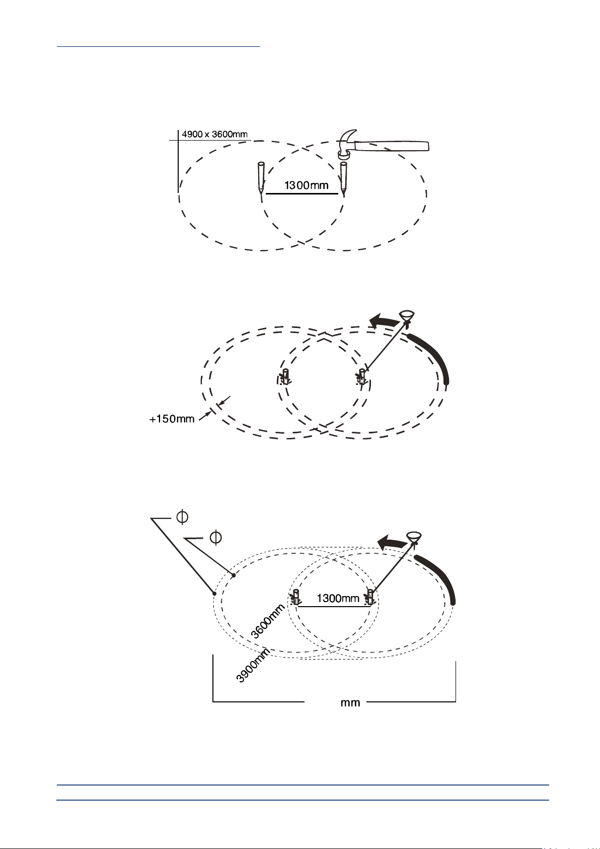
II. Marking the site
1. Mark the center of the site and drive a stake or screw driver into the soil (see diagram 2).
Diagram 2
2. Tie a piece of string onto the stick. At the other end of the string, tie a funnel. The distance between the stick and the
funnel should be 150 mm more than the radius of the pool (see diagram 3).
Diagram 3
3. Place flour or chalk dust into the funnel and draw a circle around the stake. If the smallest diameter is 3600 mm, then
the 2 circles should be 3900 mm in diameter (see diagram 4).
Diagram 4
5200
ground clearence 3900mm
pool 3600mm

WHITE POOL INSTRUCTION MANUAL pag. 10 / 29
www.cpa-piscine.it
Rev.00–16/10/20
III. Levelling the area
WARNING
Levelling is extremely important: take as much time as possible to work out a site that is completely firm and levelled. Use
a carpenter’s level and straight edge to ensure that the site is completely level, flat and firm (see diagram 5). The pool
contains a huge amount of water and thousands of kilos of weight. Should the pool collapse due to unlevelled ground, it
could cause a lot of damage to property and even human injury or death!
Diagram 5
Remove the higher ground rather than filling the low laying ground (see diagram 6).
WARNING
Always remove grass and stones within the circle. Use ground sheet to ensure that the grass doesn’t penetrate the pool liner
and cause damage.
Diagram 6
Spread a light layer of fine brick layers sand over the foundation area. Level this layer evenly (see diagram 7) . Once the site
has been cleared and levelled, it is time to start assembling the frame assembly.
Diagram 7
remove high spots
do not fill low spots
WHITE POOL INSTRUCTION MANUAL pag. 11 / 29
www.cpa-piscine.it
Rev.00–16/10/20
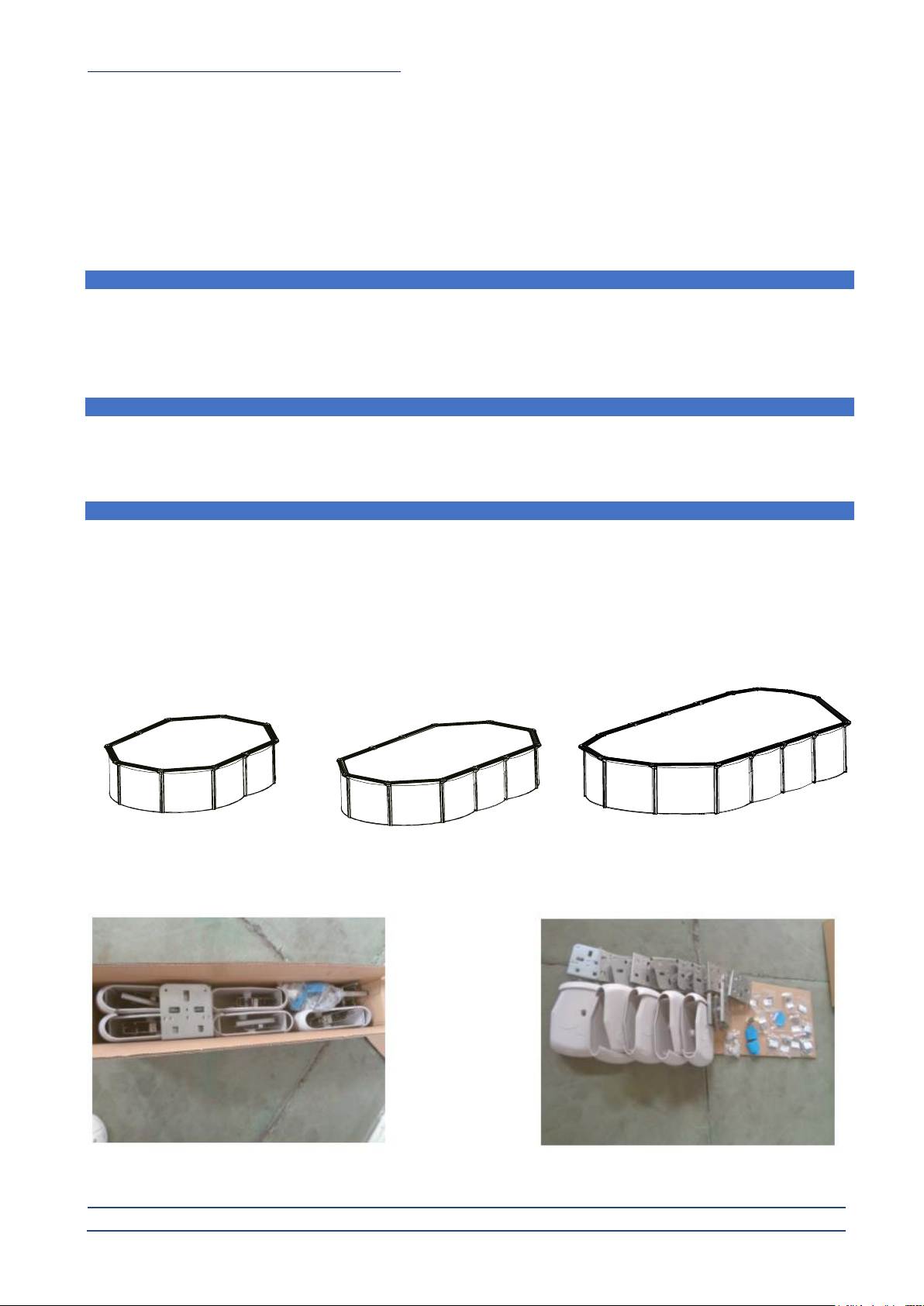
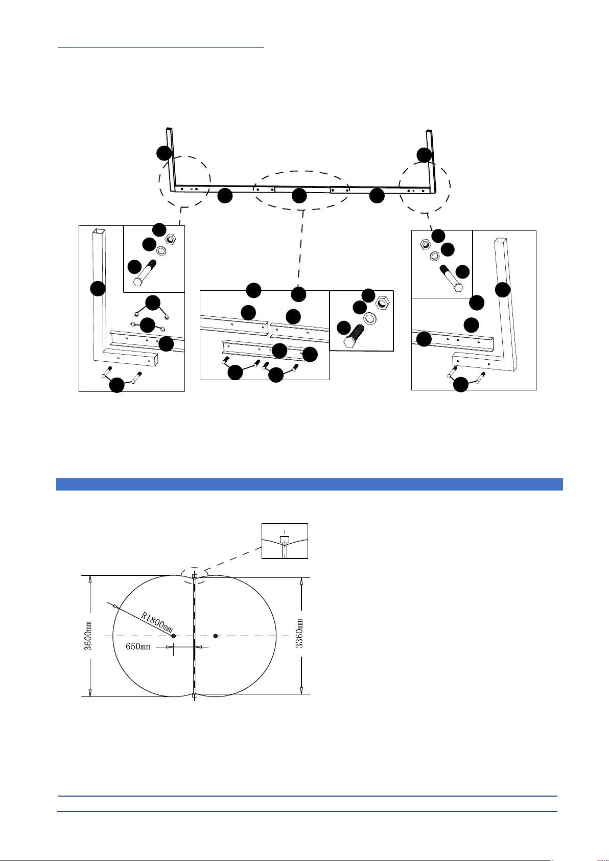
IV. Pool frame assembly
Unpack all off the components and check the parts against the checklist. See diagram 8, the same L support (21), fixing
plate (22) and connection plate (23) are used for below items.
Diagram 8
See diagram 9, the same L support (21), fixing plate (22) and connection plate (23) are used for below items .
Diagram 9
Item No.
Description
Pool dimensions (mm)
8011015
White Pool 490
L4900 x W3600 x H1300
8011012
White Pool 610
L6100 x W3600 x H1300
8011013
White Pool 730
L7300 x W3600 x H1300
Item No.
Description
Pool dimensions (mm)
8011014
White Pool 910
L9100 x W4600 x H1300
21 21
2222 23
21 21
22 22
23
21 21
21 21
22 22
23
WHITE POOL INSTRUCTION MANUAL pag. 12 / 29
www.cpa-piscine.it
Rev.00–16/10/20
Connect the L support (21), fixing plate (22) and connection plate (23) as shown in diagram 8-10, using the nut (24), washer
(25) and bolt (27) provided in the screw bag.
Diagram 10
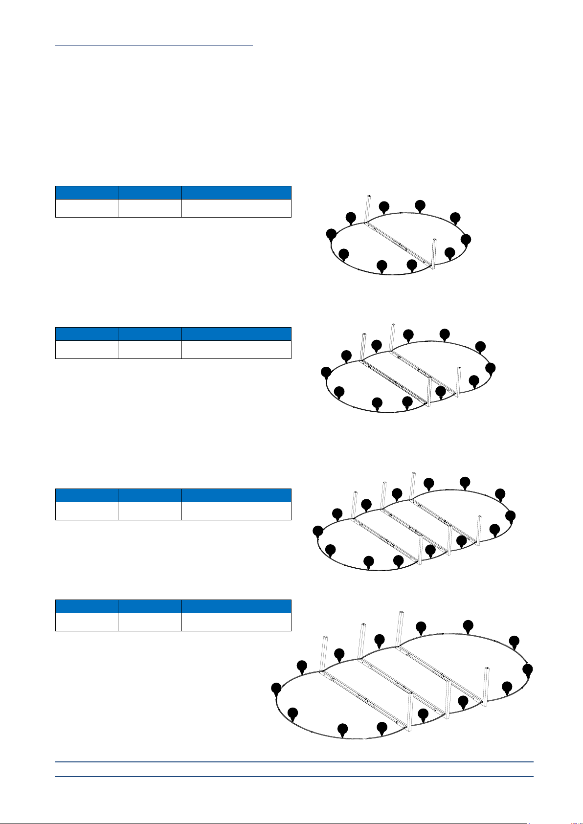
Once the frames have been correctly assembled and all of the nuts and bolts have been tightened, it’s time to position the
assembled frames onto the pool site.
Please refer to the layout size of pool you have purchased.
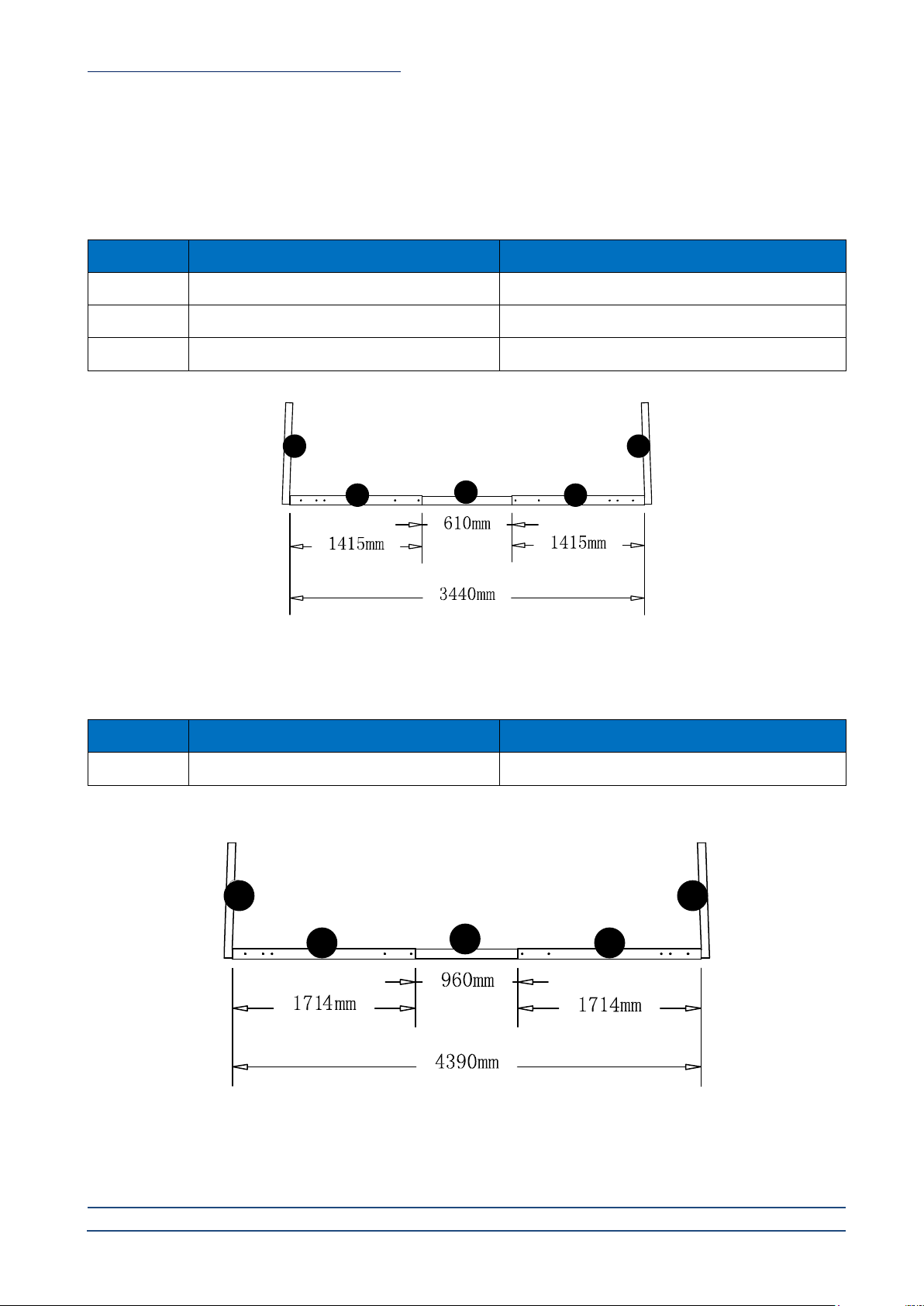
WHITE POOL 490 - 8011015
Place the assembled frame upright across the width of the
pool at a point 2450mm from the end of the cleared area (see
diagram 11).
Diagram 11
21
21 24
25
24
25 24
25 24
25
22 23 23 22
21
27 26 27
26
21
22 2223
27
2524 2425
27
24
25
26
WHITE POOL INSTRUCTION MANUAL pag. 13 / 29
www.cpa-piscine.it
Rev.00–16/10/20
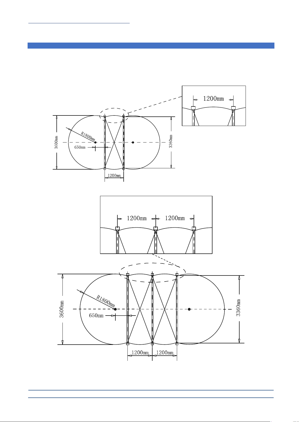
WHITE POOL 610 –8011012 WHITE POOL 730 - 8011013
Place the 1st assembled frame upright across the width of the pool at a point 2450 mm from the end of the cleared area. Place
the 2nd and the remaining assembled frames at a point 1200 mm from the center line of the adjacent assembled frame (see
diagram 12 and 13).
Note: 1200 mm measurements are taken from the center of the L supports.
Diagram 12
Diagram 13
WHITE POOL INSTRUCTION MANUAL pag. 14 / 29
www.cpa-piscine.it
Rev.00–16/10/20
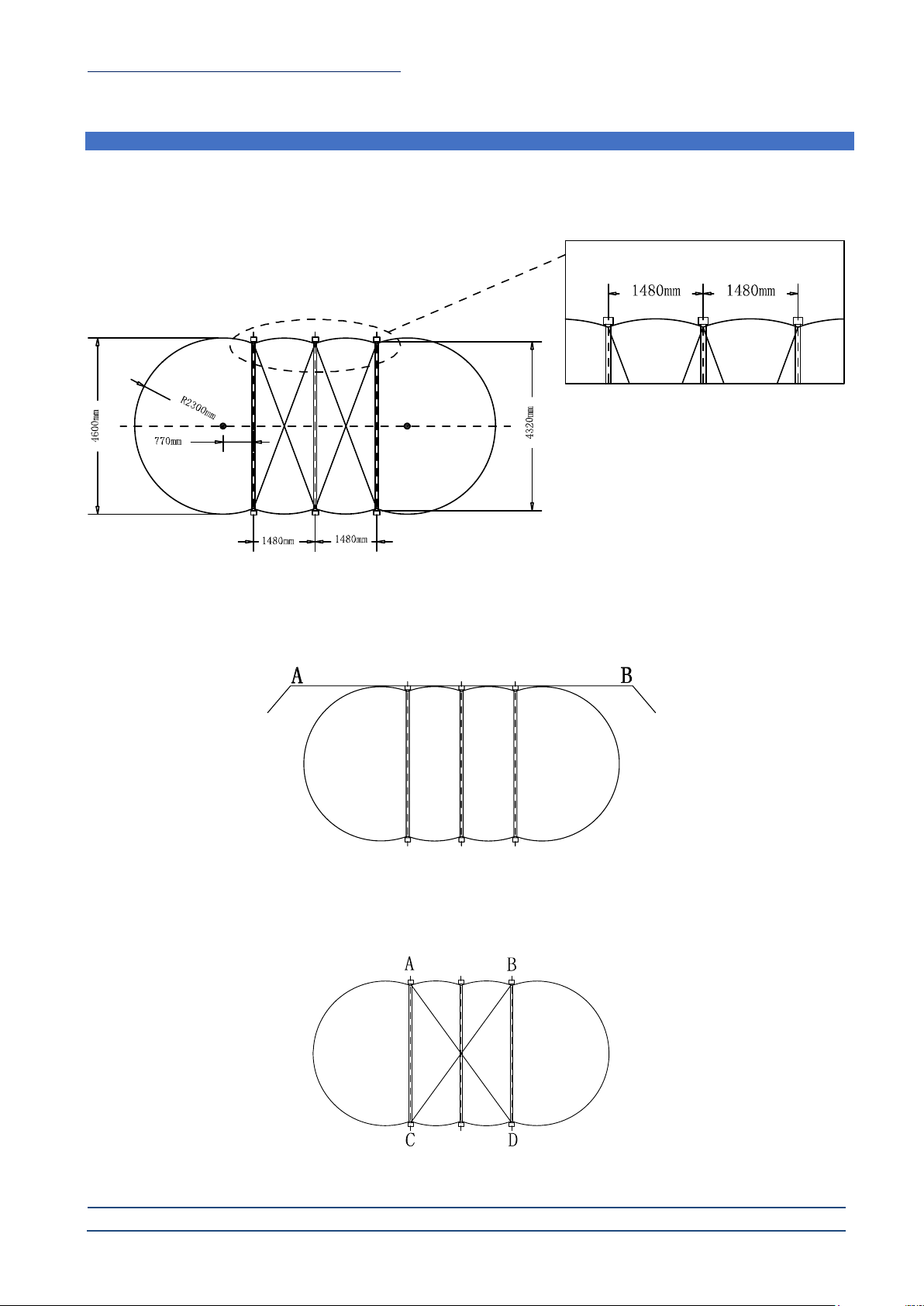
WHITE POOL 910 - 8011014
Place the 1st assembled frame upright across the width of the pool at a point 3070 mm from the end of the cleared area.
Place the 2nd and the remaining assembled frames at a point 1480 mm from the center line of the adjacent assembled frame (see
diagram 14).
Note: 1480 mm measurements are taken from the center of the L supports.
Diagram 14
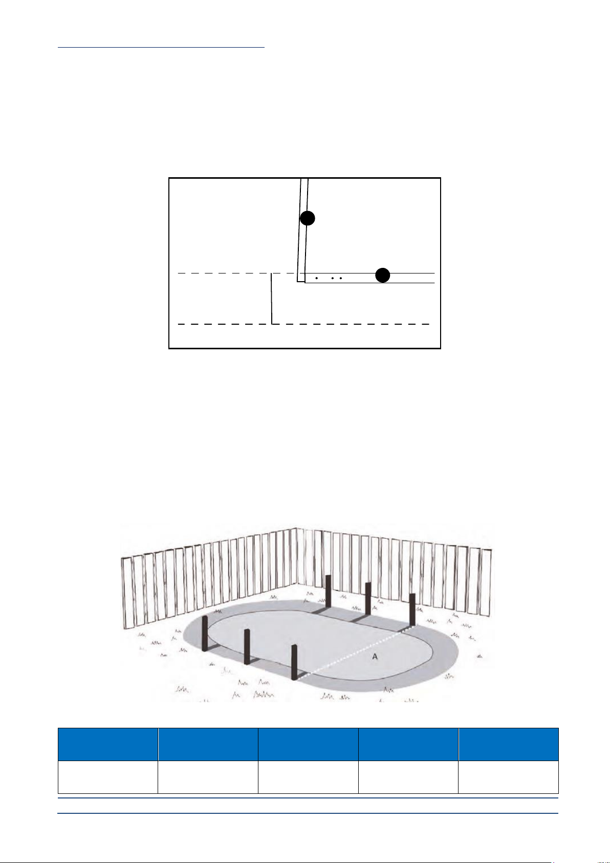
To check the alignment of the assembled frames, position string line along the back of the assembled frames (the back of the L
support) about 200 mm above the ground between two steel pegs, position A and B as shown in diagram 15. If the L Supports are
not correctly aligned, they need to be tapped back or forward until the back of each L Support is correctly aligned with the string
line.
Diagram 15
Once the steps have been completed you need to check the diagonal measurements of the pool frame. Measure the two intersecting
axes to ensure that the two straight sections are parallel. The measurements of the points A to D and B to C must be equal (see
diagram 16).
Diagram 16
picchetto picchetto

WHITE POOL INSTRUCTION MANUAL pag. 15 / 29
www.cpa-piscine.it
Rev.00–16/10/20
When all the assembled frames are in the correct position, spray paint a line on either side of each assembled frame across the
pool. This is to mark out the areas to be excavated. When these areas have been marked out, the assembled frames can be removed
from the site.
The marked areas should be excavated to a depth of 150 x 150 mm wide across the pool from one side to the other with a length
250 mm x depth 150 mm excavation at each end for the positioning of the pre-cast concrete blocks.
Note:
•If using cement mix instead of concrete blocks, the cement mix is put in place after the assembled frames have been
positioned and leveled.
•Concrete pads: the use of concrete blocks or concrete mix at each end of the assembled frame is critical as it
distributes the load carried by the frames evenly into the soil below. Not using concrete pads will result in the frame
sinking into the ground and disturbing the level of your pool.
•Do not use house bricks or Besser blocks.
•Backfill all excavated area with 8 to 1 sand and cement mix.
•Top of the horizontal section of L supports and ground should be level.
Note: if using cement mix instead of concrete blocks the cement mix is put in place after the assembled frames have been positioned
and leveled.
22
250mm
250mm
150mm
21
150mm
ground line
excavation depth
WHITE POOL INSTRUCTION MANUAL pag. 16 / 29
www.cpa-piscine.it
Rev.00–16/10/20
V. Installing assembled frames
The assembled frames can now be positioned back in to the excavated areas. Using the existing string line, ensure the L
supports side of the pool are perfectly aligned, if not, make the necessary adjustments. Care must be taken to ensure the
measure between the centers. It is advisable to hold the posts into position using steel pegs. Frames installed in such a way
that no horizontal part of the L support is situated higher that the surrounding ground level.
The levelling of the assembled frame is an important exercise that must be done precisely and repeatedly until correct.
When all the assembled frames have been positioned and levelled you need to recheck and ensure that the back of the L supports
are all in line and the diagonal measurements of the assembled frames are all correct and equal.
Before proceeding check the measurements for the width of the pool between the inside of the assembled frames should be as per
table below. The width measurements A can have a variance of + or –5mm.
If all of the measurements and levels are correct you can now proceed with the backfill of the channels across the pool and cement
mix at the end of the channels.
When positioning the L Supports for your pool, it is important that the supports are supported and retained in a perpendicular
position while the excavation is being packed.
A simple and effective way to achieve this is to drive a star picket into the ground at the rear of the L support, then temporarily
attach the L support to the star picket with some duct tape. This will hold the post vertical while the cement and backfill is put into
place.
Note: top of the horizontal L supports and ground should be level.
Model Size
White pool 490
8011015
White pool 610
8011012
White pool 730
8011013
White pool 910
8011014
Distance A
3440mm
3440mm
3440mm
4390mm
21
22
150mm
ground line
excavation depth

WHITE POOL INSTRUCTION MANUAL pag. 17 / 29
www.cpa-piscine.it
Rev.00–16/10/20
Place the pre-cast
concrete blocks
under the L supports
WHITE POOL INSTRUCTION MANUAL pag. 18 / 29
www.cpa-piscine.it
Rev.00–16/10/20
VI. Assembling the pool base rails
Cover the ground with a levelled layer of sand and lay the ground sheet (3).
Unpack all of the components and check the parts against the checklist. Slide the bottom rail into the metal piece.
Important: leave about 1 cm between the 2 ends of the bottom rail.
Repeat this process for all bottom rails (see diagram 17).
Diagram 17
Item No.
Description
Pool dimension (mm)
8011015
White Pool 490
L4900 x W3600 x H1300
Item No.
Description
Pool dimension (mm)
8011012
White Pool 610
L6100 x W3600 x H1300
Item No.
Description
Pool dimension (mm)
8011013
White Pool 730
L7300 x W3600 x H1300
Item No.
Description
Pool dimension (mm)
8011014
White Pool 910
L9100 x W4600 x H1300
9A
9A
9A
9A
9A
9A
9A
9A
9A
9A
9A
9B
9A
9A
9A
9A 9A
9A 9A
9A
9A
9A
9B
9B
9B 9B
9C
9C
9C
9C
9C
9C
9C
9C
9C
9C
9C
9C
9C
9C
9A
9A
9A 9A
9A
9A
9A
9A
9A
9A

WHITE POOL INSTRUCTION MANUAL pag. 19 / 29
www.cpa-piscine.it
Rev.00–16/10/20
VII. Fine adjustment of the bottom rails diameter
When all the rails are slided into the metal pieces, it should form a complete circle and the diameter should be equivalent to the
diameter of the pool itself. You can shorten or lengthen the gap distance between the 2 ends of bottom rails (see diagram 18).
Diagram 18
inside of pool
outside the pool
9A
9A
9A
9A
9A
9A
9A
9A 9A
9A
9A
9A
9B
9B
21 9B
9B
9B
9B
22
14
WHITE POOL INSTRUCTION MANUAL pag. 20 / 29
www.cpa-piscine.it
Rev.00–16/10/20
VIII. Fixing the pool wall
Put the pool wall on a ground cloth, cardboard or a piece of ply wood (see diagram 19). This is to protect the levelled ground while
installation of pool wall is taking place. Make sure the square window (for skimmer) is on the upward side.
It is advisable to wear protective gloves when handling the metal wall.
Diagram 19 Diagram 20
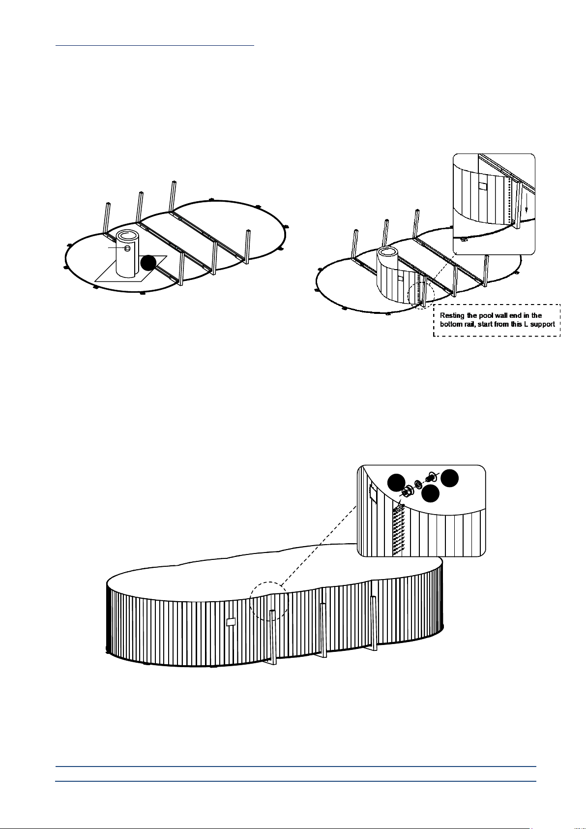
You should decide where the skimmer and filtration system should be placed. The opening end of the pool wall closest to the
square window should be placed on the closest metal piece to your selected location for the electric supply of the filtration system.
The pool wall end should be resting in the bottom rail (see diagram 20). Make sure that this location is not in a windward position.
Square window should be in the upward position.
Diagram 21
Then uncoil the whole pool wall onto the ground rail. Join the 2 ends of the pool wall together. Line up the screw holes. If you
could not line up the holes, then adjust the gap distance of the 2 ends of bottom rails (see diagram 21).
18
17
16
skimmer
opening 1
This manual suits for next models
7
Table of contents
Other C.P.A. Swimming Pool manuals


Popular Swimming Pool manuals by other brands


BWT
BWT Pool'N Box Junior Installation and operating instructions

Outside Living Industries
Outside Living Industries ubbink Ocea 510 - H120 cm Note of assembly

Steinbach
Steinbach 011005G instruction manual

Banzai
Banzai Aqua Sports Water Park manual

Intex
Intex 128362GN owner's manual

Teuco
Teuco 641 user manual


