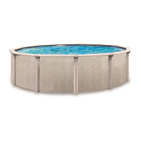
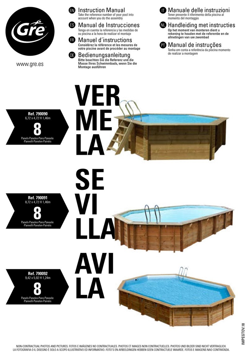
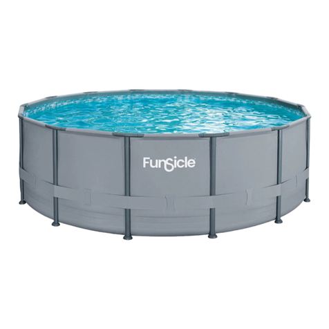
Trevi 211 User manual

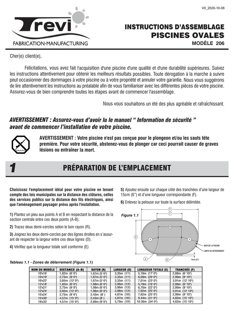
Choisissez l'emplacement idéal pour votre piscine en tenant
compte des lois municipales sur la distance des clôtures,
celles des services publiques sur la distance des fils
électriques, ainsi que l'aménagement paysager prévu après
l'installation.
1) Plantez un pieu aux points A et B en respectant la distance de
la section centrale entre ces deux points (A-B).
2) Tracez deux demi-cercles selon le bon rayon (R).
3) Joignez les deux demi-cercles par des lignes droites en
s’assurant de respecter la largeur entre ses deux lignes (D).
4) Vérifier que la longueur totale soit conforme (E)
5) Ajoutez ensuite sur chaque côté des tranchées d’une largeur
de 15cm (6”) et d’une longueur correspondante (F).
6) Enlevez la pelouse sur toute la surface délimitée.
Cher(e) client(e),
Félicitations, vous avez fait l'acquisition d'une piscine d'une qualité et d'une durabilité supérieures. Suivez les
instructions attentivement pour obtenir les meilleurs résultats possibles. Toute dérogation à la marche à suivre peut
occasionner des dommages à votre piscine ou à votre propriété et annuler votre garantie. Nous vous suggérons de lire
attentivement les instructions au préalable afin de vous familiariser avec les différentes pièces de votre piscine. Assurez-
vous de bien comprendre toutes les étapes avant de commencer l'assemblage.
Nous vous souhaitons un été des plus agréable et rafraîchissant.
AVERTISSEMENT : Assurez-vous d’avoir lu le manuel “ Information de sécurité ”
avant de commencer l’installation de votre piscine.
AVERTISSEMENT : Votre piscine n'est pas conçue pour le plongeon et/ou les
sauts tête première. Pour votre sécurité abstenez-vous de plonger
car ceci pourrait causer de graves lésions ou entraîner la mort.
PRÉPARATION DE L’EMPLACEMENT
1
NIVELLEMENT DU TERRAIN ET EXCAVATION
2
Tableau 1.1 - Zones de déterrement (Figure 1.1)
NIVELLEMENT DU TERRAIN
Pour une installation de piscine ovale on doit absolument faire un
fond plat.
Nivelez la surface très attentivement en utilisant un
niveau de menuisier et une planche très droite. Éliminez toutes
les petites buttes de terre. Assurez-vous d'avoir un terrain
exempt de tous débris tels que pierres, bois, etc.
TRANCHÉES POUR L’EMPLACEMENT DES ÉQUERRES
(COULOIRS)
1) Creusez des couloirs pour atteindre une profondeur égale à la
somme de l’épaisseur des dalles de ciment (dalles de 2”
recommandées) et de l’épaisseur des équerres 8cm (3 1/4”).
(Se référer aux illustrations pour le dessin des couloirs).
2) S’assurer que ces couloirs soient plats et de niveau sans les
compacter.
3) Disposer les les dalles de ciment dans les tranchées en
s’assurant qu’elles soient de niveau et que le dessus des dalles
arrive à 8cm (3 1/4”) de profondeur. Une fois que les équerres
y sont déposées, le dessus des équerres doivent être de niveau
avec la surface du sol prévue pour la piscine.
1,67m (5' 6")
1.67m (5' 6")
3,35m (11')
3,35m (11')
6,09m (20' 0")
7,01m (23' 0")
2,99m (9' 10")
3,91m (12' 10")
NOM DU MODÈLE
DISTANCE (A-B)
RAYON (R) LARGEUR (D) LONGUEUR TOTALE (E) TRANCHÉE (F)
10'x19' 2.75m (9' 0")
10'x22' 3.65m (12' 0")
1,67m (5' 6") 3,35m (11') 5,18m (17' 0") 2,08m (6' 10")
10'x16' 1,82m (6' 0")
2,43m (8' )
2,89m (9' 6")
4,87m (16')
5,79m (19')
9,44m (31' 0")
10.36m (34' 0")
4,82m (15' 10")
4,82m (15' 10")
15'x30' 4,57m (15' 0")
18'x33' 4,57m (15' 0")
1,98m (6' 6")
2,43m (8' )
3,96m (13')
4,87m (16') 7,62m (25' 0")
3,91m (12' 10")
2.99m (9' 10")
12'x24' 3,65m (12' 0")
15'x24' 2,75m (9' 0")
1,98m (6' 6") 3,96m (13') 5,79m (19' 0") 2,08m (6' 10")
12'x18' 1,82m (6' 0")
7,62m (25' 0")
AB
A-B
R
R
D
15cm (6”)
E
F
PAROI DE LA PISCINE
LIMITE DE DÉTERREMENT
10" 10" 10"
(25cm) (25cm) (25cm) (25cm) (25cm)
154" (391 cm)
60" (152cm) (12-24)
10" 10"
3-1/4" (8cm)
DEEP
26"
31" (79cm)
6"
(66cm)
R
10x22, 12x24
26"
(66cm)
26"
(66cm)
26"
(66cm)
(43cm)
17"
48" (122cm)
48" (122cm)
(15cm)
36" (92cm) (10x16)
Creusez un trou de 30 cm (12") de largeur par environ 25 cm (10") de
profondeur en plein centre de la circonférence.
Creusez une tranchée d'environ 15 cm (6") de largeur à partir du trou
central jusqu'à l'emplacement du moteur de la piscine. La terre retirée sera
déposée à côté de la tranchée car elle servira à enterrer le tuyau.
Assemblage du drain
Placez du téflon autour du bouchon fileté et vissez-le dans le trou du drain.
Collez le raccord dans l'ouverture prévue à cet effet.
Prenez une des rondelles de caoutchouc et ajustez-la sur le dessus du drain
en prenant bien soin d’aligner les trous. Fixez-la ensuite avec des lanières
de ruban adhésif afin d’éviter que le sable ne pénètre dans les trous une fois
le drain installé.
Fixez une des extrémités du tuyau noir ou blanc dans l'embout du drain, en
prenant soin au préalable d'appliquer de la colle sur l'embout du drain et à
l'intérieur de l'extrémité du tuyau. Et, surtout, entourez-le d'un ou deux
collets.
Coupez le tuyau de façon à ce qu'il se termine avec la fin de la poussière
de roche ou de sable. On calcule le rayon de la piscine plus 15 cm (6") à
partir du centre du drain.
Placez le drain de fond assemblé dans le trou de façon à ce qu'il soit environ
1,3 cm (1/2") plus haut que la terre de surface. Enterrez le tuyau, plaçant
le drain le plus possible de niveau. Compactez avec les pieds et le pilon.
Mélangez trois pelletées de poussière de roche ou de sable avec une demi-
pelletée de ciment pur et un peu d'eau et placez ce ciment autour du drain
jusqu'à 1,3 cm (1/2") sous le dessus du drain.
INSTALLATION DU DRAIN DE FOND (optionnel)
3
Figure 1.1
10" 10" 10"
(25cm) (25cm) (25cm)
82" (208 cm)
60" (152cm) (12x18)
6"
R
10x16, 12x18
26"
(66cm)
26"
(66cm)
48" (122cm)
48" (122cm)
3-1/4" (8cm)
DEEP
31" (79cm)
(43cm)
17"
(15cm)
36" (92cm) (10x16)
10" 10" 10"
(25cm) (25cm) (25cm) (25cm)
118" (299 cm)
96" (243cm) (15x24)
10"
3-1/4" (8cm)
DEEP
31" (79cm)
6"
(15cm)
R
10x19, 15x24
26"
(66cm)
26"
(66cm)
26"
(66cm)
(43cm)
17"
48" (122cm)
48" (122cm)
36" (92cm) (10x19)
10" 10" 10"
(25cm) (25cm) (25cm) (25cm) (25cm)
190" (482 cm)
96" (243cm)
10" 10"
3-1/4" (8cm)
DEEP
26"
31" (79cm)
6"
(66cm)
R
15x30
26"
(66cm)
26"
(66cm)
26"
(66cm)
(43cm)
17"
48" (122cm)
48" (122cm)
(15cm)
(25cm)
10" 26"
(66cm)
10" 10" 10"
(25cm) (25cm) (25cm) (25cm) (25cm)
190" (482 cm)
132" (335cm)
10" 10"
3-1/4" (8cm)
DEEP
26"
31" (79cm)
6"
(66cm)
R
18x33
26"
(66cm)
26"
(66cm)
26"
(66cm)
(43cm)
17"
48" (122cm)
48" (122cm)
(15cm)
(25cm)
10" 26"
(66cm)
Tableau: Quantités de sable
3,05 m x 6,70 m (10’ x 22’) 2 Tonnes 1 Tonne
3,05 m x 5,79 m (10’ x 19’) 2 Tonnes 1 Tonne
3,05 m x 4,87 m (10’ x 16’) 2 Tonnes 1 Tonne
INSTRUCTIONS D’ASSEMBLAGE
PISCINES OVALES
Trevi 211 / 213

1) Positionnez les pilliers de support assemblés de l’étape 4 sur
les dalles dans les tranchées préalablement creusées.
2) Se reférer à l’illustration 5.1 : une fois les pilliers disposés
dans les tranchées, Insérez l’attache de rainure dans les rainures
de la section droite entre les montants et fixez les sur les
poutrelles horizontales à l’aide de vis standards #14.
3) Se reférer à l’illustration 5.2 : fixez les plaques de renfort
entre les poutrelles horizontales à l’aide de 4 vis standards #14.
RAINURE AU SOL
SECTION DROITE
VIS STANDARD #14
ATTACHE DE RAINURE
1) Consultez les illustrations et le tableau et étudiez-les
attentivement. Vous pouvez maintenant assembler les bandes de
tension métalliques. Référez-vous aux indications du tableau pour
le nombre de rangées de bandes métalliques à assembler et le
nombre de bandes par rangée en fonction des dimensions de
piscine.
2) Se reférer à l’illustration 6.1: S’il y a plusieurs bandes par
section, assembler les bandes de tension ensemble avec 4
boulons et écrous (BB) 1/4" #20 X 5/8" (6,35 mm X 15,88 mm),
en prenant soin de placer la tête du boulon sur le dessus.
3) Fixer les bandes de tensions ainsi assemblées aux poutrelles
horizontales des deux côtés, à l'aide de 4 vis standards #14.
MODÈLE 10x16 10x19 10x22 15x30 18x33
345 6 6
NOMBRE DE RANGÉES À ASSEMBLER
NOMBRE DE BANDES TOTAL
NOMBRE DE BANDES PAR RANGÉE 222 2 2
3 4 5 12 18
12x18 12x24 15x24
354
222
6108
Tableau
1) Sections A et B, se reférer à l’illustration 7.1:
Placez le bout tronqué de la rainure sur la poutrelle horizontale
du dernier pillier de la section droite et fixez-la à l’aide d’une vis
standard #14. À l’autre bout, placez la première plaque de la
section ronde.
2) Section ronde, se reférer à l’illustration 7.2 :
Prenez les rainures de rayon et les plaques de rainure et
commencez par la première plaque de la section ronde. Répétez
jusqu'à ce que le "demi-cercle" soit complété.
2) Se reférer à l’illustration 7.3. Avant de procéder à l’étape
suivante, assurez-vous que le centre de votre piscine soit au trait
carré et que les bandes de métal soient bien tendues.
1) Se reférer à l’illustration 4.1. Pour assembler, fixer les
équerres (R) à la poutrelle horizontale (Q) à l'aide du boulon 1/2"
X 3" X #13 (12,7 mm X 76,2 mm) (U) des écrous (UU) et des
rondelles (V). N’oubliez pas d’insérer un tube d’espacement (T)
à l’intérieur des poutrelles vis-à-vis chaque boulon.
2) Se reférer à l’illustration 4.2. Fixer les montants à l'aide du
boulon 1/2" X 3" X #13 (12,7 mm X 76,2 mm) (U) des écrous
(UU) et des rondelles (V). N’oubliez pas d’insérer un tube
d’espacement (T) ainsi que deux rondelles (V) à l’intérieur des
montants vis-à-vis chaque boulon.
3) Se reférer à l’illustration 4.3. Recouvrir les têtes de boulon
avec les capuchons pour boulons (W) et insérer les embouts de
mousse (X) aux deux extrémités des poutrelles horizontales.
CAPUCHON POUR BOULON 1/2”
EMBOUT DE MOUSSE
ASSEMBLAGE DES RAINURES DES SECTIONS COURBES
7
ASSEMBLAGE DES PILLIERS DE LA SECTION DROITE
4
INSTALLATION DE LA PAROI
8
ASSEMBLAGE DES BANDES DE TENSION
6
RAINURES SECTION DROITE ET PLAQUES DE RENFORT
5
ÉQUERRE
RONDELLE 1/2”
ÉCROU 1/2”
POUTRELLE HORIZONTALE
TUBE D’ESPACEMENT
BOULON 1/2” X 3”
VIS STANDARD #14
PLAQUE DE RENFORT
1) Déverser le sable.
2) Choisissez l'emplacement du filtreur vis-à-vis une section
courbe (jamais une section droite). Le point de départ se fera
vis-à-vis cet emplacement pour que les trous d'écumoire et de
retour d'eau soient les plus près possible du filtreur.
3) Avant de dérouler la paroi, assurez-vous que les orifices
prévus pour l'écumoire et le retour d'eau se trouvent bien au haut
de la paroi et face à l'endroit où se trouvera le filtreur.
1ERE RAINURE (A)
SECTION RONDE
1ERE PLAQUE DE RAINURE
AU SOL SECTION RONDE
BOUT
TRONQUÉ
RAINURE AU SOL
SECTION DROITE
Illustration 7.1
Illustration 5.2
Illustration 5.1
MONTANT DU
PILLIER DE SUPPORT
Illustration 4.1
Illustration 4.3
Illustration 4.2
Illustration 7.2
Illustration 7.3
PILLIERS ASSEMBLÉS
Illustration 6.1

Avant de placer la toile contre la paroi, introduisez le boyau d'un
aspirateur dans l'orifice du retour d'eau jusqu'à environ 15 cm
(6") du sol.
F
ixez le boyau en place à l'aide de ruban adhésif. Bouchez
également l'orifice de l'écumoire avec du ruban adhésif. Cette
opération a pour but d'éliminer les fuites d'air.
Déposez la toile pliée au centre de la piscine perpendiculaire à
l'orifice de l'écumoire. Prenez soin de porter des chaussures
légères à semelles plates pour vous déplacer sur le fond de
sable car la moindre empreinte de talon pourrait être visible une
fois la piscine remplie.
Dépliez délicatement la toile et amenez la bordure de celle-ci à la
base du mur. Assurez-vous que le côté rugueux de la toile soit
dessous et que le côté avec motif soit sur le dessus.
Installez la rainure stabilisatrice sur le mur. Amenez la toile par-
dessus le sommet du mur en la laissant excéder entre 10 cm à
15 cm (4" à 6") à l'extérieur du mur. Maintenez ensuite la toile en
place à l'aide d'un coupleur de plastique.
Vers la fin de cette étape, il peut arriver que la toile soit trop
tendue et difficile à rabattre ou qu'elle soit au contraire trop
lâche.
Vous devrez alors retirer certains coupleurs et ajuster de
nouveau la toile afin de mieux répartir la tension.
Detail de l’installation de la toile avec jonc d’accrochage.
Accrochez la toile sur le sommet du mur et installez la rainure
stabilisatrice par dessus la toile.
L'aspirateur est ensuite mis en marche pour que la toile adhère
à la paroi. C'est à ce moment que vous verrez si elle est trop
tendue dans le bas ou si elle est plissée à certains endroits.
Ajustez la toile en enlevant au besoin des coupleurs pour la
soulever ou l'abaisser afin de lui faire prendre une forme parfaite.
Finalement, vous pouvez introduire l'eau et la laisser monter
jusqu'au bas de la paroi avant d'arrêter l'aspirateur et de le retirer.
RETOUR D'EAU
Vous pouvez installer le retour d'eau une fois l'aspirateur retiré.
Placer l'anneau de retour d'eau contre la toile et ajustez-le pour
qu'il soit parfaitement aligné avec le trou de la paroi.
Une fois l'anneau ajusté et tenu en place, coupez la toile au
centre de l'anneau. Insérez le retour d'eau de l'intérieur en plaçant
le premier joint entre le retour d'eau et la toile et le deuxième
entre la paroi et la toile. Ensuite, serrez l'anneau de l'extérieur
avec de grosses pinces en faisant attention de pas plisser la
toile.
DRAIN DE FOND (optionnel)
Palpez le milieu de la toile pour trouver les trous et vissez ensuite
l'anneau et son joint contre la toile avant de découper la toile du
centre de l'anneau, puis, vissez le couvercle du drain.
INSTALLATION DE LA TOILE DE VINYLE
10
228
(EN OPTION)
230
Étendez environ 10 cm (4") de sable à compactage au bas de la
paroi intérieure de façon à former un remblai destiné à protéger
la toile des extrémités coupantes des rainures inférieures et de la
poussière de roche (si applicable), ou installez une doucine
préfabriquée, si disponible.
FINITION DU FOND DE SABLE
Égalisez une dernière fois le sable de finition. Assurez-vous qu'il
ne subsiste pas de roche coupante, de débris ou de racine en
surface. Pour une meilleure protection, arrosez le sable et
tassez-le de nouveau jusqu'à ce que le fond soit bien lisse.
FINITION DU FOND DE SABLE
9
INSTALLATION DES PLAQUES DU HAUT
11
Insérez la paroi dans la rainure inférieure en commençant au
centre d'une plaque. Au départ, une ou deux barres de soutien
maintiennent la paroi en place. Une personne déroule la paroi sur
un madrier ou une planche, tandis qu'une autre personne l'insère
dans la rainure inférieure. On ne doit pas dérouler plus de 3 m
(10') sans mettre en place une barre de soutien pour renforcer la
structure.
Une fois le déroulage terminé, il peut arriver que la paroi soit trop
longue ou que les deux extrémités ne se rejoignent pas de
quelques centimètres. Vous devrez alors déplacer légèrement la
paroi vers l'intérieur ou l'extérieur. Si cela ne suffit pas, il vous
faudra rouler la paroi, réaligner les fentes des plaques à rainures
inférieures et recommencer le déroulage. Si l'écart est trop
grand, mesurez la longueur de la paroi et comparez-la au tableau
ci-dessous.
Lorsque vous joindrez le mur d'acier, assurez-vous que le côté
renforcé par le pli soit à l'intérieur du cercle, faisant face à la toile
et que l'autre côté soit à l'extérieur du mur (voir l’illustration 8.1).
IMPORTANT : Compte tenu de l'énorme pression qui sera
exercée par l'eau sur le mur, il est absolument essentiel que tous
les boulons soient serrés à un minimum de 60 lbs/po et un
maximum de 95 lbs/po et qu'aucun trou ne soit laissé ouvert.
Toutes les têtes de boulons doivent être à l'intérieur et
l’écrou/rondelle à l'extérieur. Recouvrez toutes les têtes de
boulons d'un ruban adhésif épais.
Tableau
Illustration 8.1
3,66 m X 5,48 m (12’ X 18’) 15,16 m (61’ 9 3/8’’)
3,05 m X 6,70 m (10’ X 22’) 17,04 m (55’ 11’’)
3,05 m X 5,79 m (10’ X 19’) 15,21 m (49’ 11’’)
3,05 m X 4,87 m (10’ X 16’) 13,38 m (43’ 11’’)
Ne pas utiliser de pistolet à chocs
(impact gun) pour visser les murs.
Serrage minimum de 60 livres pouce
et maximum de 85 livres pouce
ATTENTIONATTENTION
ATTENTION
Joindre les bouts des murs en
orientant les plis vers l’extérieur.
ATTENTION
ATTENTION
INSTALLATION DE LA PAROI (suite)
8
Deposez les plaques du haut sur les parties supérieures
des montants verticaux.
Maintenez-les en place à l'aide de (2) vis “Z” de chaque
coté de la plaque.
‘’Z‘’

INSTALLATION DES COUVRE-JOINTS DE SIÈGES
14
Positionnez l’enseigne des normes de sécurité à l’extérieur de la
piscine sur le côté le plus voyant de la piscine.
Installez quatre (4) étiquettes de sécurité à l’intérieur de la
piscine de façon à ce que l’on voit toujours une des étiquettes
peu importe d’où le baigneur entre dans l’eau.
(Voir dessin pour le positionnement)
INSTALLATION DES ÉTIQUETTES
15
INSTALLATION DES SIÈGES
13
INSTALLATION DES MONTANTS VERTICAUX
12
MONTAGE DU SYSTÈME DE FILTRATION
16
Note : Voir le manuel “ Les Informations de sécurité”, page 1.
Tel que décrit dans le manuel, toutes les composantes du
système de filtration doivent être positionnées de façon à
empêcher un enfant de grimper dessus et d’avoir accès à la
piscine. Le système de filtration doit être à 1m (40po) de la paroi
de la piscine.
À l'aide d'un peu de poussière de roche ou de sable, placez une
dalle de patio de 61 cm x 76 cm (24" x 30") de niveau avant d'y
installer le moteur et le filtreur.
Placez le moteur sur la dalle et insérez-y les deux embouts
nécessaires pour recevoir les tuyaux.
Ensuite, installez la bonbonne du filtreur. Ajustez bien l'élément
de filtration dans son canal. On doit parfois assembler les
manchons de l'élément de filtration.
Bouchez le trou central de l'élément de filtration à l'aide du
bouchon pour permettre le déversement du sable de filtrage
dans la bonbonne.
Retirez le bouchon. Installez le joint dans l'entaille et fixez la tête
du filtreur en plaçant la position de refoulement (back wash) du
côté opposé à la piscine.
Assurez vous de vérifier la verticalité des montant
verticaux avant de placer les sièges.
Placez les sièges sur les parties supérieures des
montants verticaux.
Centrez les sièges entre les deux poteaux et maintenez-les
en place à l'aide de quatre (4) vis “Z”.
Fixez les montants aux plaques à rainures inférieures à
l’aide des vis “Z” que vous trouverez dans le sac de
quincaillerie.
Le poteau rentre dans les deux encoches du rail du bas.
Il est à noter que les montants s’installent à l’extérieur de
la partie retroussée de la plaque à rainures.
‘’Z‘’
‘’Z‘’
Accrochez le couvre-joint sur le rebord intérieur des
sièges et l’enclencher sur le montant vertical.
Fixez-le à l’aide d’une vis “Z” sur le dessus.
Accrochez le cap dans la partie superieur couvre-joint et
enclenchez-le à la base du couvre-joint.
COUVRE-JOINT
CAP
‘’Z‘’
COUVRE-JOINT

LISTE DES PIÈCES
18
Insérez des embouts filetés, s'il y a lieu, de façon à pouvoir fixer
la valve dans l'écumoire.
Raccordez le tuyau du drain à l'embout du bas. Raccordez le
tuyau du moteur à l'embout de côté.
Tous les embouts filetés doivent être recouverts de ruban en
téflon sur les filets avant d'être fixés afin d'éviter les fuites d'eau.
Le téflon sera apposé sur le filetage de la façon suivante : sur les
premiers filets (cela facilite l'introduction) et plusieurs couches
vers la fin des filets (permetant une meilleure étanchéité).
MONTAGE DE LA VALVE DE DRAIN (optionnel)
17
Retirez le bouchon. Installez le joint dans l'entaille et fixez la tête
du filtreur en plaçant la position de refoulement (back wash) du
côté opposé à la piscine.
Posez les embouts nécessaires, puis, raccordez les tuyaux à
l'aide de collets.
1- Le premier tuyau rejoint le dessus de la pompe à côté de la
tête du filtreur;
2- le deuxième se rend du moteur à l'écumoire (ou à la valve du
drain de fond); et,
3- le troisième, du devant de la tête du filtreur au retour d'eau ou
du devant du chlorinateur au retour d'eau.
Un tuyau de refoulement peut être placé à l'arrière de la tête du
filtreur (back wash).
S'il y a un chlorinateur et/ou une thermopompe, on doit les
assembler à la sortie du filtreur.
1m
(40 ‘’)
72 120 96 144 144
ITEM DESCRIPTION 12x18 12x24 15x24 15x30 18x33
10 10 12 12 14
4861010
29
11111
10 10 12 12 14
4861010
8 8 10 10 12
8 8 10 10 12
8 8 10 10 12
14 18 18 22 24
10 10 12 12 14
4861010
10 10 12 12 14
4861010
610 8 12 12
61081212
61081212
61081212
12 20 16 24 24
4861010
24 40 32 48 48
24 40
24 40
24 40
12 20 16 24 24
61081218
50 50 50
Nombre de sections courbes
Nombre de sections droites
PAROI (LONGUEUR RÉELLE, PIEDS-POUCES)
BOULON & ÉCROU POUR PAROI 52" (OU 54")
TOILE INTÉRIEURE
11111
COUPLEUR EN PLASTIQUE (VENDU SÉPARÉMENT)
SIÈGE - SECTION RONDE
SIÈGE - SECTION DROITE
PLAQUE DU BAS
MONTANT 52'' OU 54''
PLAQUE DU HAUT
COUVR-JOINT DE SIÈGE
RAINURE AU SOL - SECTION RONDE
RAINURE AU SOL - SECTION DROITE
RAINURE STABILISATRICE - SECTION RONDE
RAINURE STABILISATRICE - SECTION DROITE
ASSEMBLAGE PILLIER DE SUPPORT
MONTANT DU PILLIER DE SUPPORT
PLAQUE DU HAUT SECTION DROITE
POUTRELLE HORIZONTALE
EQUERRE DU PILLIER DE SUPPORT
PLAQUE DE RENFORT
TUBE D'ESPACEMENT
BOULON 1/2" X 3" X #13 (12,7 mm X 76,2 mm)
ÉCROU 1/2" (12,7 mm)
RONDELLE 1/2" (12,7 mm)
CAPUCHON POUR BOULON 1/2"
EMBOUT DE MOUSSE POUR POUTRELLE
BANDE DE TENSION
BOULON ET ÉCROU 1/4" #20 X 5/8" (6,35 mm X 15,88 mm)
AA
BB
CC
DD
A
B
C
D
E
F
G
J
K
L
O
P
Q
R
S
T
U
UU
V
W
X
Y
BB
Z
158
226 210 278 296
VIS STANDARD (VIS #14 , 1" LONG.)
61081212
CAP COUVRE JOINT
N
6 10 8 12 12
ATTACHE DE RAINURE
M
8 8 10 10 12
CAP
H
61' 9 3/8''
(18,83m) 65' 2 1/2''
(19,88m) 77' 2 1/2''
(23,53m) 86' 7 9/16''
(26,40m)
32 48 48
32 48 48
32 48 48
25 25
49' 9 3/8''
(15,16m)
29 29 29 29
72 120 96
10x16 10x22 10x19
10 10 10
486
29
111
10 10 10
486
888
888
888
14 18 16
10 10 10
486
10 10 10
486
610 8
6108
6108
6108
12 20 16
486
24 40 32
24 40
24 40
24 40
12 20 16
6108
50
111
192
260 226
6108
6108
14 18 16
49' 11''
(15,21m) 55' 11''
(17,04m)
32
32
32
25 25
43' 11''
(13,38m)
29 29
BB MNZT
U
UU V
SECTION RONDE
H
AA
F
G
Z
Z
Z
Z
K
L
SECTION DROITE
F
Z
P
BB
N
Z
O
TZ
W
UV
R
Q
X
UU
Z
S
M
BB
V
Z
Z
H
MONTAGE DU SYSTÈME DE FILTRATION (SUITE)
16

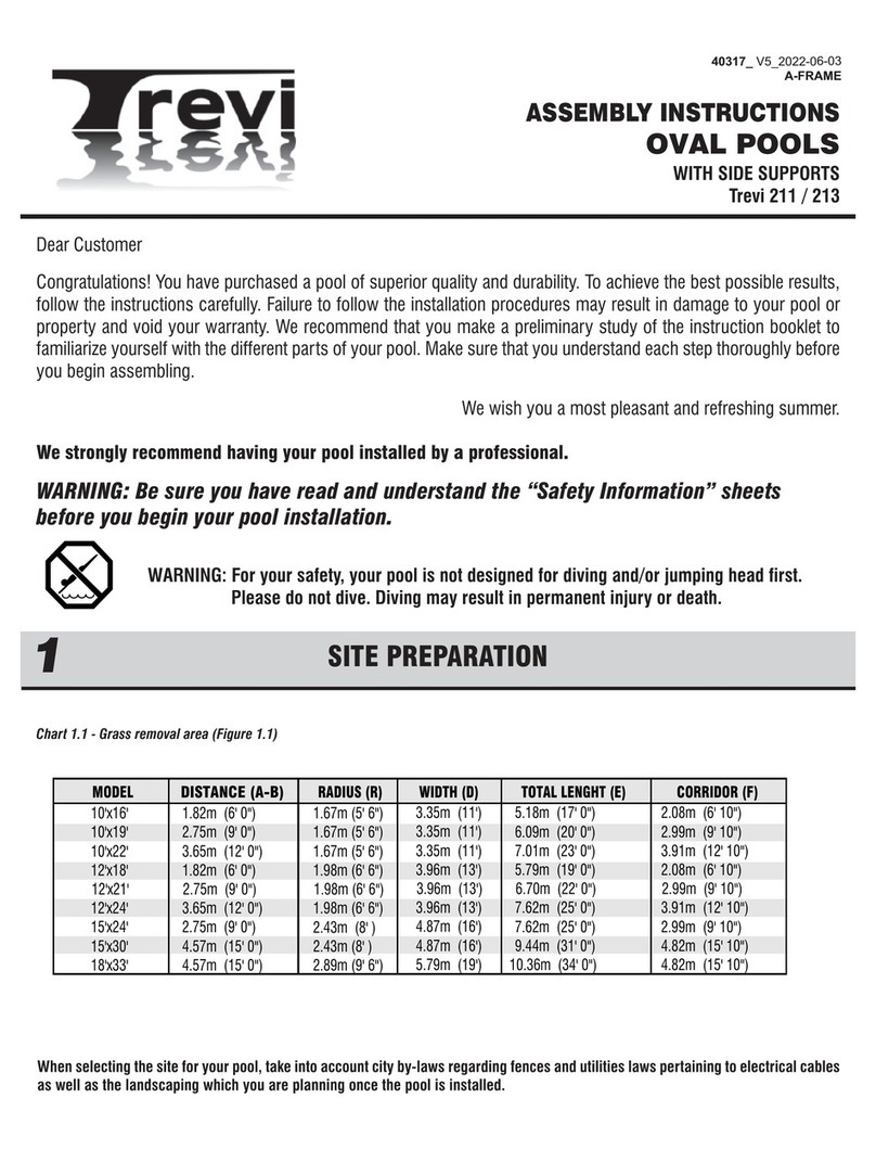
When selecting the site for your pool, take into account city
by-laws regarding fences and utilities laws pertaining to
electrical cables, as well as the landscaping which you are
planning once the pool is installed.
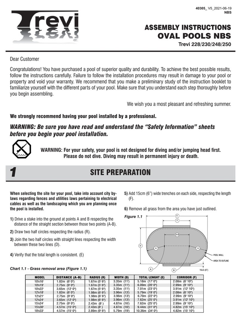
1) Drive a stake into the ground at points A and B respecting the
distance of the straight section between those two points (A-B).
2) Draw two half circles respecting the radius (R).
3) Join the two half circles with straight lines respecting the
width between these two lines (D).
4) Verify that the total length is consistent. (E)
5) Add 15cm (6”) wide trenches on each side, respecting the
lenght (F), to leave room for the stays.
6) Remove all grass from the area which you have just outlined.
Dear Customer
Congratulations! You have purchased a pool of superior quality and durability. To achieve the best possible results, follow
the instructions carefully. Failure to follow the installation procedures may result in damage to your pool or property and
void your warranty. We recommend that you make a preliminary study of the instructions booklet to familiarize yourself
with the different parts of your pool. Make sure that you understand each step thoroughly before you begin assembling.
We wish you a most pleasant and refreshing summer.
WARNING: Be sure you have read and understood the “Safety Information”
sheets before you begin your pool installation.
WARNING: For your safety, your pool is not designed for diving and/or jumping head first.
Please do not dive. Diving may result in permanent injury or death.
SITE LEVELLING AND EXCAVATION
2
Dig a hole 30 cm (12") wide by approximately 25 cm (10") deep
in the center of the circumference.
From the center hole to the projected location of the pool motor,
dig a 15 cm (6") wide trench. Place the removed soil aside to
be used later to cover the hose.
Bottom Drain Assembly
Place teflon around the threaded plug. Screw in drain holes
using large pliers. Glue the connector in the appropriate
opening.Glue connector in the appropriate opening.
Take one of the two rubber rings and adjust it to the top of the
drain, aligning the holes carefully. Secure with strips of adhesive
tape to prevent sand from penetrating inside the holes once the
drain has been installed.
Secure one end of the long black or white hose inside the drain
spout. First apply glue on the drain spout and inside the drain
end, then secure with one or two collars.
Cut the hose so that it ends with the stone dust (or sand).
Measure the pool radius from the center of the drain, then add
15 cm (6").
Place the assembled bottom drain in the hole so that it is
approximately 1.3cm (1/2") higher than the surface soil. Bury
the hose, levelling the drain as much as possible. Compact the
soil, using your feet and a tampering tool as well.
Mix three (3) shovels of stone or sand dust with one half shovel
of pure cement, adding a small quantity of water, then pour the
cement around the drain until it reaches 1.3 cm (1/2") from the
top.
BOTTOM DRAIN ASSEMBLY (if applicable)
3
Chart 1.1 - Grass removal area (Figure 1.1)
AB
A-B
R
R
D
15cm (6”)
E
F
POOL WALL
AREA TO OUTLINE
Figure 1.1
SITE LEVELLING
For an oval pool, the bottom must absolutely be levelled, using a
carpenter's level and a straight plank. Eliminate any protrusions.
Ensure that the surface is free of debris such as rocks, wood,
etc.
TRENCHES FOR BUTTRESS ASSEMBLIES
1) Dig trenches to a depth equal to the sum of the thickness of
the patio blocks (2” thick slabs recommended) and the
thickness of the butress assembly beam 8cm (3 1/4”). (Refer to
illustrations for trenches layout details).
2) Make sure trenches are smooth and leveled without
compacting them.
3) Place and level patio blocks into trenches. Make sure that the
top of the slabs is at a depth of 8cm (3 1/4”). Top of framework
must be level with pool area.
Chart: Sand quantity
3.05 m x 6.70 m (10’ x 22’) 2 Ton.s 1 Ton.
3.05 m x 5.79 m (10’ x 19’) 2 Ton.s 1 Ton.
3.05 m x 4.87 m (10’ x 16’) 2 Tons 1 Ton.
1,67m (5' 6")
1.67m (5' 6")
3,35m (11')
3,35m (11')
6,09m (20' 0")
7,01m (23' 0")
2,99m (9' 10")
3,91m (12' 10")
10'x19' 2.75m (9' 0")
10'x22' 3.65m (12' 0")
1,67m (5' 6") 3,35m (11') 5,18m (17' 0") 2,08m (6' 10")
10'x16' 1,82m (6' 0")
2,43m (8' )
2,89m (9' 6")
4,87m (16')
5,79m (19')
9,44m (31' 0")
10.36m (34' 0")
4,82m (15' 10")
4,82m (15' 10")
15'x30' 4,57m (15' 0")
18'x33' 4,57m (15' 0")
1,98m (6' 6")
2,43m (8' )
3,96m (13')
4,87m (16') 7,62m (25' 0")
3,91m (12' 10")
2.99m (9' 10")
12'x24' 3,65m (12' 0")
15'x24' 2,75m (9' 0")
1,98m (6' 6") 3,96m (13') 5,79m (19' 0") 2,08m (6' 10")
12'x18' 1,82m (6' 0")
7,62m (25' 0")
MODEL
DISTANCE (A-B)
RADIUS (R) WIDTH (D) TOTAL LENGHT (E) CORRIDOR (F)
ASSEMBLY INSTRUCTIONS
OVAL POOLS
Trevi 211 / 213
SITE PREPARATION
1
10" 10" 10"
(25cm) (25cm) (25cm) (25cm) (25cm)
154" (391 cm)
60" (152cm) (12-24)
10" 10"
3-1/4" (8cm)
DEEP
26"
31" (79cm)
6"
(66cm)
R
10x22, 12x24
26"
(66cm)
26"
(66cm)
26"
(66cm)
(43cm)
17"
48" (122cm)
48" (122cm)
(15cm)
36" (92cm) (10x16)
10" 10" 10"
(25cm) (25cm) (25cm)
82" (208 cm)
60" (152cm) (12x18)
6"
R
10x16, 12x18
26"
(66cm)
26"
(66cm)
48" (122cm)
48" (122cm)
3-1/4" (8cm)
DEEP
31" (79cm)
(43cm)
17"
(15cm)
36" (92cm) (10x16)
10" 10" 10"
(25cm) (25cm) (25cm) (25cm)
118" (299 cm)
96" (243cm) (15x24)
10"
3-1/4" (8cm)
DEEP
31" (79cm)
6"
(15cm)
R
10x19, 15x24
26"
(66cm)
26"
(66cm)
26"
(66cm)
(43cm)
17"
48" (122cm)
48" (122cm)
36" (92cm) (10x19)
10" 10" 10"
(25cm) (25cm) (25cm) (25cm) (25cm)
190" (482 cm)
96" (243cm)
10" 10"
3-1/4" (8cm)
DEEP
26"
31" (79cm)
6"
(66cm)
R
15x30
26"
(66cm)
26"
(66cm)
26"
(66cm)
(43cm)
17"
48" (122cm)
48" (122cm)
(15cm)
(25cm)
10" 26"
(66cm)
10" 10" 10"
(25cm) (25cm) (25cm) (25cm) (25cm)
190" (482 cm)
132" (335cm)
10" 10"
3-1/4" (8cm)
DEEP
26"
31" (79cm)
6"
(66cm)
R
18x33
26"
(66cm)
26"
(66cm)
26"
(66cm)
(43cm)
17"
48" (122cm)
48" (122cm)
(15cm)
(25cm)
10" 26"
(66cm)

1) Dump the sand.
2) Choose the filter location beside a round section (never a straight
section). The starting point will be at that location so that the
skimmer and return holes are as close as possible to the filtration
system.
3) Before uncoiling the wall, make sure the pre-punched holes for
the skimmer and pump return are at the top and facing the planned
location of your filter.
SRTAIGHT SECTION BUTTRESS ASSEMBLY
4
1) Refer to Illustration 4.1. To assemble, join splice brackets
(R) to the horizontal beam (Q) using the bolt 1/2 "X 3" X #13
(12.7 mm x 76.2 mm) (U), nuts (UU ) and washers (V).
Remember to insert a spacer (T) inside the beams aligned to
each bolt.
2) Refer to Illustration 4.2. Assemble the post using bolts
1/2" X 3" X #13 (12,7 mm X 76,2 mm) (U), nuts (UU) and
washers (V). Remember to insert a spacer (T) and two washers
(V) inside the beam aligned to each bolt.
3) Refer to Illustration 4.3. Cover the bolt heads with bolt
caps (W) and insert the styrofoam caps (X) at both ends of foot
beam.
1/2” BOLT CAP COVER
STYROFOAM CAP
SPLICE BRACKET
WASHER 1/2”
NUT 1/2”
FOOT BEAM
SPOOL SLEEVE
BOLT 1/2” X 3”
BUTTRESS POST
Illustration 4.1
Illustration 4.3
Illustration 4.2
1) Position the buttress pillars assembled in Step 4 on the patio
blocks in the trenches previously dug.
2) Refer to Illustration 5.1 : Once the buttress pillars are
placed in the trenches, assemble the straight sections bottom
tracks (J) between the pillars by fixing them on the bottom track
jonction and fixe them to the foot beams using standard screws
#14.
3) Refer to Illustration 5.2 : Fix the pressure plates between
foot beams using 4 standard screws #14.
BOTTOM TRACK
STRAIGHT SECTION
STANDARD
SCREW #14
BOTTOM TRACK JONCTION
BOTTOM TRACKS (STRAIGHT) AND PRESSURE PLATES
5
STANDARD
SCREW #14
PRESSURE PLATE
Illustration 5.2
Illustration 5.1
1) Study illustrations and chart carefully. You are now ready to
assemble the metallic tension straps. Refer to indications on the
chart for the exact number of tension straps and sections per
straps according to their respective pool size.
2) Refer to Illustration 6.1: If there is more than one metallic
strap per tension strap rows, assemble the straps together using 4
bolts and nuts (BB) 1/4" #20 X 5/8" (6,35 mm X 15,88 mm),
taking care of placing the bolt head on top.
3) Attach the assembled tension straps to foot beams on both
sides, using 4 standard screws #14.
POOL SIZE 10x16 10x19 10x22 15x30 18x33
345 6 6
ROWS TO ASSEMBLE
TENSION STRAPS QUANTITY (TOTAL)
STRAPS PER ROW 222 2 2
3 4 5 12 18
12x18 12x24 15x24
354
222
6108
Chart
TENSION STRAPS ASSEMLBY
6
BUTTRESS ASSEMBLY
Illustration 6.1
1) Sections A and B, refer to Illustration 7.1 :
Place the short end of the bottom track on the foot beam of the
last pillar of the straight section and secure it with a standard
screw # 14. At the other end, place the first foot plate of the
round section.
2) Round section, refer to Illustration 7.2 :
Using the round section bottom tracks and the foot plates, start
with the first plate of the round section. Repeat this procedure
until the half circle is completed.
3) Refer to Illustration 7.3 :
Before going to next step, make sure that the centre of the pool
is properly squared and metallic tension straps are stretched.
ROUND SECTIONS BOTTOM TRACKS ASSEMBLY
7
WALL INSTALLATION
8
SAND
PLANKS SUPPORT
BAR
1ST TRACK (A)
ROUND SECTION
1ST FOOT PLATE
ROUND SECTION
SHORT END
BOTTOM TRACK
STRAIGHT SECTION
Illustration 7.1
Illustration 7.2
Illustration 7.3

Before pulling the liner up against the wall, insert a vacuum
cleaner hose down into the pump return hole to approximately
15 cm (6") from the ground.
Maintain the hose in place with adhesive tape. Don't forget to
block the skimmer hole with adhesive tape to prevent air from
leaking in.
Place the unfolded liner in the center of the pool area at right
angles with the skimmer hole. Make sure you wear light, flat-
soled shoes to walk on the sand as the slightest heel mark could
be visible once the pool is filled.
Carefully unfold the liner, bringing the bottom-sidewall seam
close to the wall base. Make sure that the side with the
protruding seams faces downward or that the patterned side
faces upward.
Install the plastic coupler on the wall (optionnal). Lift up a
section of the liner over the top of the wall leaving a 10 cm to 15
cm (4" to 6") fringe outside the wall. Secure the liner with a
plastic coupler then install the joiner plates on top of each
upright.
At this point, the liner may be too tight, making it difficult to
drape the overlap or, on the contrary, too loose. In such cases,
you will have to redistribute the tension in the liner by remo-ving
some of the couplers and readjusting the liner.
Installation detail of the u-bead liner.
Hang the liner on the top of the wall and install the square
stabiliser to secure.
Start the vacuum cleaner to allow the liner to adhere to the wall
and check for excess tension at the bottom or for wrinkles.
Adjust the liner by removing couplers if needed, to lift or lower it
in order to ensure a perfect fit.
Fill the pool up to the base of the wall before stopping and
removing the vacuum cleaner.
PUMP RETURN FITTING
After you remove the vacuum cleaner, you may install the return
fitting. Place the return fitting ring against the liner and adjust it
so that it is perfectly aligned with the hole in the wall.
When the ring is properly positioned and secured, cut the liner in
the middle of the ring. Insert the return fitting from the inside,
placing the first gasket between the return fitting and the liner
and the second between the wall and the liner. Then tighten the
outside ring with large pliers, taking care not to crease the liner.
BOTTOM DRAIN (optional)
Find the holes through the middle of the liner and screw the ring
and gasket in against the liner before cutting the liner in the
middle of the ring, then screw on the drain cover.
VINYL LINER INSTALLATION
10
You can now spread approximately 10 cm (4") of compacting
sand all around the inside base of the wall in order to protect the
liner from the cutting edges of the bottom wall tracks and the
stone dust (if applicable). Or install a prefabricated cove, if
available.
SAND BASE FINISHING
Level finishing sand one last time. Make sure that any sharp
stones, debris or roots have been removed from the surface. For
better protection, spray sand with water and pack it once more
until the base is nicely even.
SAND BASE FINISHING
9
WALL INSTALLATION (continued)
8
Begin inserting the wall into the bottom wall tracks in the middle
of a joiner plate. At first, the wall is kept in place with one or two
support bars (or extra persons). One person uncoils the wall on
a beam or a plank, while a second person inserts it in the bottom
wall tracks. Do not uncoil more than 3 m (10') of wall before you
install a support bar to reinforce the structure.
Once the wall is completely uncoiled, you may find that it is too
long or that both ends do not meet by a few centimetres. If such
is the case, you must gently push the wall in or out. If this does
not work, roll up the wall again, realign the grooves and uncoil
the wall again. If the spread is too wide, measure the wall and
check it against the following chart.
When you prepare to join the ends of the wall, make sure the end
that is reinforced by the fold is inside the circle, facing the liner
and that the other end faces outward (Illustration 8.1).
When the wall joint is secured, install the round stabilisers on top
of it.
IMPORTANT: Due to the enormous pressure exerted by the
water on the steel wall, it is absolutely essential that all the bolts
are tighten to a minimum of 60 in-lbs and maximum of 85 in-lbs
and no hole is left open. All bolt heads must be inside with
nut/washer outside. Cover all bolt heads with heavy fabric tape.
Chart
Illustration 8.1
JOINER PLATE INSTALLATION
11
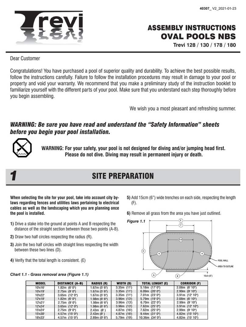
3,66 m X 5,48 m (12’ X 18’) 15,16 m (61’ 9 3/8’’)
3,05 m X 6,70 m (10’ X 22’) 17,04 m (55’ 11’’)
3,05 m X 5,79 m (10’ X 19’) 15,21 m (49’ 11’’)
3,05 m X 4,87 m (10’ X 16’) 13,38 m (43’ 11’’)
Do not use impact gun for wall screws.
Minimum clamping force of 60 inch pounds
to maximum of 85 inch pounds
WARNING
WARNINGWARNING
Join the ends of the wall with plies
facing outward.
WARNING
WARNING
228
(OPTIONAL)
230
Put the joiner plate on the upper side of the upright, and
secure with two (2) screw “Z” on each side.
‘’Z’’
SCREW

Note: See 'Safety Information" Manual, Page 1.
As described in the manual, all components of the filtration
system should be placed to prevent a child to climb on top and
get access to the pool. Filtration system must be install at
1m (40’’) from the pool wall.
Using a little bit of stone dust (or sand), place at level a patio
stone 61 cm x 76 cm (24" x 30") before installing the motor and
filter
Position the motor on the stone and insert the two nozzles to
connect the hoses.
Then, install the filter tank. Adjust the lateral assembly pro-perly
in its channel.
It is sometimes necessary to install the laterals.
Patch the center hole of the lateral assembly using the plug to
allow filtering sand to flow into the tank.
Remove the plug. Install the joint in the cavity and secure the
filter head by placing the back wash position on opposite side of
the pool.
Position the Safety procedures panel on the outside of the pool.
This panel must be at the most visible place from the yard on
your pool.
Place the four (4) safety stickers inside the pool in a way that it’s
seen from any entry point of the swimmer (See positionning
drawing).
SECURITY SIGNS INSTALLATION
15
SEAT CAP INSTALLATION
14
TOP SEAT INSTALLATION
13
FILTRATION SYSTEM ASSEMBLY
16
Be sure to have a vertical upright before installing the top
seat.
Place the top seat on the upper side of the upright.
Center the top seat between the two uprights and secure
with four (4) screw “Z”.
VERTICAL UPRIGHT INSTALLATION
12
Attach the uprights to the bottom joiner plates with two (2)
screws “Z”, witch you will find them in the hardware bag.
Uprights must be installed outside the flanged part of the
joiner plate and in the two notch of the wall track.
‘’Z’’
SCREW
‘’Z’’
SCREW
Put the seat cap on the inside section of the seat and
interlock with the upright. Secure the seat cap with one (1)
screw “Z”.
Snap the cap on top of the seat cap and inter-lock it on the
bottom.
SEAT CAP
TOP SEAT
CAP
SEAT CAP
‘’Z’’
SCREW
TOP SEAT

PARTS LIST
18
Insert threaded nozzles, if applicable, in order to be able to screw
the valve in the skimmer.
Connect the drain hose to the bottom nozzle. Connect the motor
hose to the side nozzle.
The threads on all threaded nozzles must be covered with teflon
tape prior to installing in order to prevent water leaks. Teflon is
applied to the threads as follows: little or none on the first few
threads (to facilitate introduction) and several layers toward the
end threads (for better watertightness).
DRAIN VALVE ASSEMBLY (if applicable)
17
Install necessary nozzles, then connect hoses using collars.
1. The first hose runs from the top of the pump to the side of the
filter head;
2. The second one goes from the pump to the skimmer (or to the
bottom drain valve);
3. The third goes from the front of the filter head to the water
return or from the front of the chlorinator to the water return.
A back wash hose may be placed behind the filter head.
If there is a chlorinator and/or heat pump, they must be
assembled at the filter exit.
1m
(40 ‘’)
Number of curved section
Number of straight section
POOL WALL (finished lenght, inch)
BOLT & NUT FOR 52" (OR 54") WALL
POOL LINER
PLASTIC COUPLER (SOLD SEPARATELY)
TOP SEAT - ROUND SECTIONS
TOP SEAT- STRAIGHT SECTIONS
FOOT PLATE
UPRIGHT 52'' or UPRIGHT 54''
TOP PLATE ROUND SECTION
SEAT CAP
BTM TRACK - ROUND SECTIONS
BTM TRACK - STRAIGHT SECTIONS
TOP TRACK - ROUND SECTIONS
TOP TRACK - STRAIGHT SECTIONS
BUTTRESS ASSEMBLY
BUTTRESS POST
TOP PLATE OVALE SECTION
FOOT BEAM
SPLICE BRACKET
PRESSURE PLATE
SPOOL SLEEVE
BOLT 1/2" X 3" X #13 (12,7 mm X 76,2 mm)
NUT 1/2" (12,7 mm)
WASHER 1/2" (12,7 mm) 72 120 96 144 144
BOLT CAP COVER
FOOT BEAM STYROFOAM CAP
TENSION STRAP
1/4" #20 X 5/8" (6,35 mm X 15,88 mm) SCREW & FLANGE NUT
STANDARD SCREW (SCREW #14 , 1" LENGHT)
ITEM DESCRIPTION 12x18 12x24 15x24 15x30 18x33
10 10 121214
4861010
11111

10 10 12 12 14
4861010
8 8 10 10 12
8 8 10 10 12
8 8 10 10 12
14 18 18 22 24
10 10 12 12 14
4861010
10 10 12 12 14
4861010
610 8 12 12
61081212
61081212
61081212
12 20 16 24 24
4861010
24 40 32 48 48
24 40
24 40
24 40
12 20 16 24 24
61081218
50 50 50
11111
AA
BB
CC
DD
A
B
C
D
E
F
G
J
K
L
O
P
Q
R
S
T
U
UU
V
W
X
Y
BB
Z
158
226 210 278 296
61081212
SEAT CAP - STRAIGHT SECTIONS
N
6 10 8 12 12
TRACK TIE PLATE
M
8 8 10 10 12
CAP
H
61' 9 3/8''
(18,83m) 65' 2 1/2''
(19,88m) 77' 2 1/2''
(23,53m) 86' 7 9/16''
(26,40m)
32 48 48
32 48 48
32 48 48
25 25
49' 9 3/8''
(15,16m)
29 29 29 29 29
72 120 96
10x16 10x22 10x19
10 10 10
486
29
111
10 10 10
486
888
888
888
14 18 16
10 10 10
486
10 10 10
486
610 8
6108
6108
6108
12 20 16
486
24 40 32
24 40
24 40
24 40
12 20 16
6108
50
111
192
260 226
6108
6108
14 18 16
32
32
32
25 25
29 29
49' 11''
(15,21m) 55' 11''
(17,04m)
43' 11''
(13,38m)
BB MNZT
U
UU V
SECTION RONDE
H
AA
F
G
Z
Z
Z
Z
K
L
SECTION DROITE
F
Z
P
BB
N
Z
O
TZ
W
UV
R
Q
X
UU
Z
S
M
BB
V
Z
Z
H
FILTRATION SYSTEM ASSEMBLY
16
Other manuals for 211
2
This manual suits for next models
1
Table of contents
Languages:
Other Trevi Swimming Pool manuals
Popular Swimming Pool manuals by other brands

GRE
GRE PEOV9159 manual

Outside Living Industries
Outside Living Industries ubbink 410-H120 cm Note of assembly

Outside Living Industries
Outside Living Industries ubbink Linea 500x800 - H140 cm Note of assembly

avenli
avenli 17792XX user manual

Bestway
Bestway POWER STEEL 5615G instructions

Bestway
Bestway InflateYourFun Fast Set owner's manual