C.P.Bourg Bourg Binder 3001 User manual

EMERGENCY
STOP
NOTSTOP
ARRET
D'URGENCE
NOODSTOP
GLUE TEMPERATURE CONTROL
LEIMTEMPERATURREGULIERUNG
REGULATION
TEMPERATURE
COLLE
LI MTEMPERATUURSTURING
OOPPEERRAATTOORR
MMAANNUUAALL
Initial issue: 12/00
Latest revision : 08/06
9.133.459

Operator Manual
Page 9 - 2 Initial issue: 12/00
Latest revision: 11/01
Content of this documentation has a confidential nature and remains the
exclusive property of C.P. Bourg SA. It is only put at the user (including without
limitation: Renter or Purchaser or their employees) disposal within the
exclusive scope of using and servicing the product. Without C.P. Bourg SA
prior agreement in writing, disclosure to third party and/or reproductions as well
as changes are prohibited.
TABLE OF CO TE TS
1. Introduction . . . . . . . . . . . . . . . . . . . . . . . . . . . . . . . . . . . . . . . . . .5
1.1 Foreword . . . . . . . . . . . . . . . . . . . . . . . . . . . . . . . . . . . . . . . . . . . . . . . . .5
1.2 Safety information . . . . . . . . . . . . . . . . . . . . . . . . . . . . . . . . . . . . . . . . . .5
1.3 Safety labels . . . . . . . . . . . . . . . . . . . . . . . . . . . . . . . . . . . . . . . . . . . . . .6
1.4 Instructions for safe use . . . . . . . . . . . . . . . . . . . . . . . . . . . . . . . . . . . . . .9
1.5 Safety data sheet . . . . . . . . . . . . . . . . . . . . . . . . . . . . . . . . . . . . . . . . . .11
2. System description . . . . . . . . . . . . . . . . . . . . . . . . . . . . . . . . . . .12
2.1 Specifications . . . . . . . . . . . . . . . . . . . . . . . . . . . . . . . . . . . . . . . . . . . .12
2.2 eneral . . . . . . . . . . . . . . . . . . . . . . . . . . . . . . . . . . . . . . . . . . . . . . . . .13
2.3 Control Panel . . . . . . . . . . . . . . . . . . . . . . . . . . . . . . . . . . . . . . . . . . . .14
2.4 Control panel menus and messages . . . . . . . . . . . . . . . . . . . . . . . . . . . .15
2.5 Change of binding parameters . . . . . . . . . . . . . . . . . . . . . . . . . . . . . . . .16
2.6 Instructions for timer use (optional) . . . . . . . . . . . . . . . . . . . . . . . . . . . . .18
2.7 Cover station . . . . . . . . . . . . . . . . . . . . . . . . . . . . . . . . . . . . . . . . . . . . .21
2.8 Milling depth adjustment . . . . . . . . . . . . . . . . . . . . . . . . . . . . . . . . . . . .27
2.9 lue . . . . . . . . . . . . . . . . . . . . . . . . . . . . . . . . . . . . . . . . . . . . . . . . . . .29
2.10 To set up the Binder module . . . . . . . . . . . . . . . . . . . . . . . . . . . . . . . .31
2.11 Output unit (optional) . . . . . . . . . . . . . . . . . . . . . . . . . . . . . . . . . . . . . .32
2.12 Binding condition . . . . . . . . . . . . . . . . . . . . . . . . . . . . . . . . . . . . . . . . .33
2.13 Cycle description . . . . . . . . . . . . . . . . . . . . . . . . . . . . . . . . . . . . . . . . .34
3. Maintenance . . . . . . . . . . . . . . . . . . . . . . . . . . . . . . . . . . . . . . . .35
3.1 Preventive maintenance . . . . . . . . . . . . . . . . . . . . . . . . . . . . . . . . . . . .35
3.2 Paper dust bag replacement . . . . . . . . . . . . . . . . . . . . . . . . . . . . . . . . .36
4. Mechanical trouble shooting . . . . . . . . . . . . . . . . . . . . . . . . . . .37
5. Some common glueing defects . . . . . . . . . . . . . . . . . . . . . . . . .38
6. Environmental compliance . . . . . . . . . . . . . . . . . . . . . . . . . . . . .39
Product Recycling and Disposal . . . . . . . . . . . . . . . . . . . . . . . . . . . . . . . . .39
7. Appendix . . . . . . . . . . . . . . . . . . . . . . . . . . . . . . . . . . . . . . . . . . .41
Operator Manual
Page 9 - 3 Initial issue: 12/00
Latest revision: 08/06

Operator Manual
Page 9 - 4 Initial issue: 12/00
Latest revision: 11/01
Cette page est intentionnellement vide.
This page is intentionally left blank.
Deze blad is opzettelijk in het wit gebleven.
Diese Seite wurde absichtlich leer gelassen.

1. I TRODUCTIO
1.1 Foreword
Thank you for choosing a BOUR product.
The
BOURG BI DER 3001
is a perfect binder destined for the off line production of bound
booklets.
This manual is a guide to operate the BOUR BINDER 3001.
Follow the instructions carefully and you should obtain years of excellent service from your
Finishing on Demand system.
If you have any difficulty using your equipment, please call us and ask for technical assistance
(phone numbers are listed on the last page). We will be delighted to help you.
1.2 Safety information
You are advised to read the "Instructions for a safe use" before you start to actually use the
device.
Technical safety information such as safety data sheet can also be found.
Where applicable, cautions and warnings are used to draw your attention to safety precautions
to be taken.
All information in this publication is based on the latest information available at the time of
approval for printing.
We reserve the right to revise this publication and to make changes in the content without
obligation to notify any person of such revisions or changes.
Operator Manual
Page 9 - 5 Initial issue: 12/00
Latest revision: 11/01

1.3 Safety labels
Please pay particular attention to the description of the following pictograms:
Caution: on a yellow background,
indicates a hazardous situation that can cause small or severe injury.
Warning: on a orange background is used to indicate a hazardous situation which
has some probability of death or severe injury. Warning should not be
considered for property damaged accidents unless personal injury risk is
present.
Danger: on a red background:indicates a hazardous situation with a high risk of
death or severe injury. The ‘danger’ sign does not apply to accidents
causing material damage, unless they can cause personal injury.
An Emergency stop on the control panel can be pressed to disable the binder.
Dangerous area. Keep hands clear !
Hot glue. Burn hazard
Operator Manual
Page 9 - 6 Initial issue: 12/00
Latest revision: 11/01
WARNING
KEEP HANDS CLEAR
CAN CAUSE
SEVERE IN URY
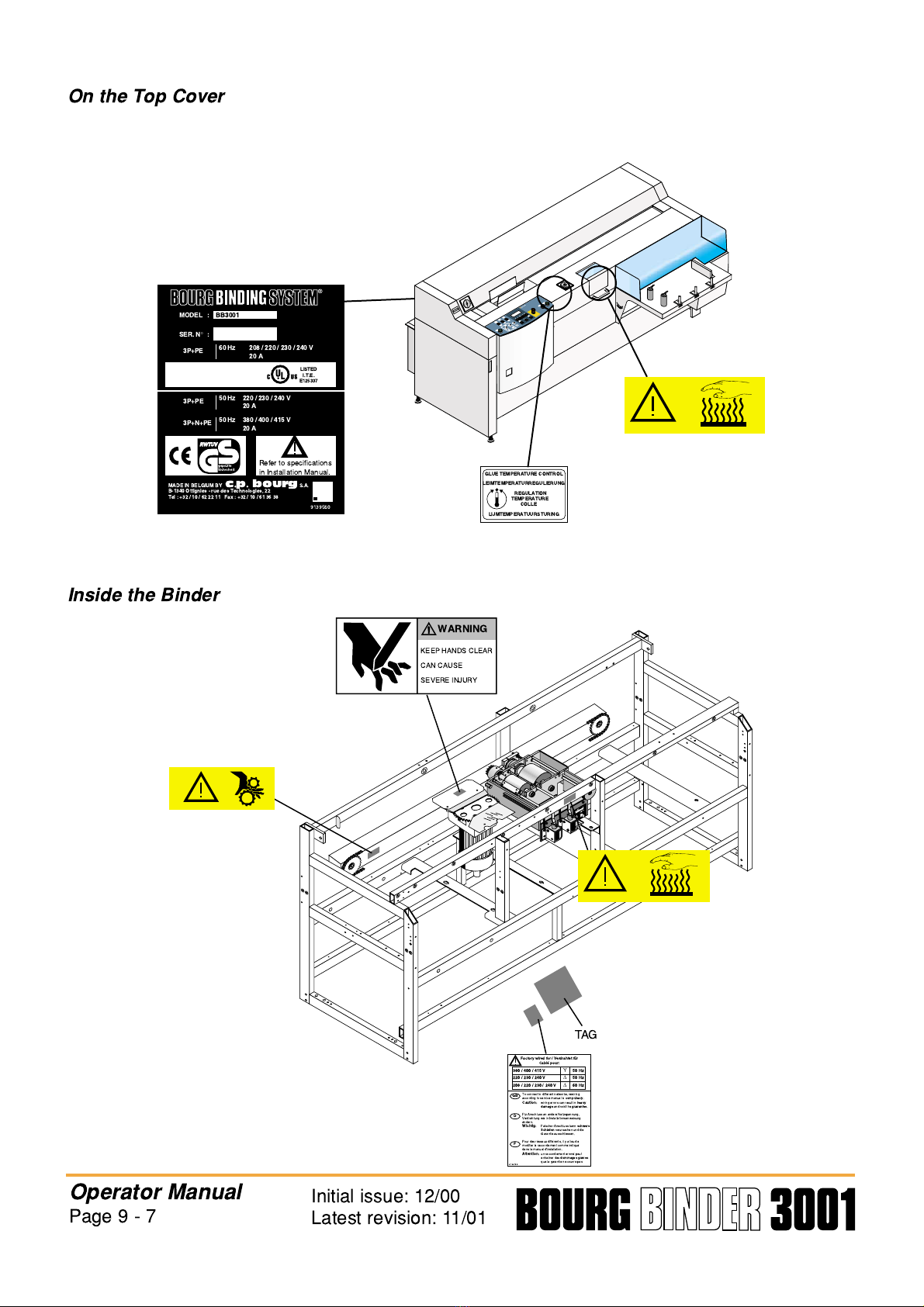
On the Top Cover
Inside the Binder
Operator Manual
Page 9 - 7 Initial issue: 12/00
Latest revision: 11/01
GLUE TEMPERATURE CONTROL
LEIMTEMPERATURREGULIERUNG
REGULATION
TEMPERATURE
COLLE
LI MTEMPERATUURSTURING
MADE IN BELGIUM BY
c p bourg
S.A.
B-1340 Ottignies - rue des Technologies, 22
Tel : +32 / 10 / 62 22 11 Fax : +32 / 10 / 61 36 38
3P+PE 50 Hz 220 / 230 / 240 V
20 A
3P+N+PE 50 Hz 380 / 400 / 415 V
20 A
9139560
gepru¨ fte
Sicherheit
Refer to specifications
in Installation Manual.
®
MODEL
SER. N
°
:
:
BB3001
3P+PE 60 Hz 208 / 220 / 230 / 240 V
20 A
LISTED
I.T.E.
E125337
WARNING
KEEP HANDS CLEAR
CAN CAUSE
SEVERE IN URY
TAG
9.139.158
Factory wired for / Verdrahtet f
u¨
r
Cabl
e´
pour:
To connect to different networks, rewiring
according to service manual is
compulsary
.
Caution:
wiring errors can result in
heavy
damage
and void the
guarantee
.
F
u¨
r Anschluss an andere Netzspannung,
Verdrahtung wie in Installationsanweisung
a¨
ndern.
Wichtig:
Falscher Anschluss kann
schwere
Sch
a¨
den
verursachen und die
Garantie ausschliessen.
Pour des r
e´
seaux diff
e´
rents, il y a lieu de
modifier le raccordement comme indiqu
e´
dans le manuel d'installation.
Attention:
un raccordement erron
e´
peut
entra
ıˆ
ner des
dommages graves
que la garantie ne couvre pas
GB
D
F
380 / 400 / 415 V
Υ
50 Hz
220 / 230 / 240 V
∆
50 Hz
208 / 220 / 230 / 240 V
∆
60 Hz

In the Power Ra k
On the ba k (inside)
Operator Manual
Page 9 - 8 Initial issue: 12/00
Latest revision: 11/01
PE
Power supply
connection
Main Ground
Pictogram
L3
L2
L1
N
9.139.163
High leakage current
earth connection essential
before
connecting supply
Courant de fuite
e´
lev
e´
Raccordement
a`
la terre indispensable
avant
le raccordement au r
e´
seau
WARNING
WHEN WIRING THE BINDER TO A
380v or 415v NETWORK AALLLL
MMUUSSTT BE
OF
THE OMISSION OF THE NEUTRAL
WILL RESULT IN HEAVY DAMMAGE
AND BBRREEAACCHH OOFF WWAARRAANNTTYY
(
B
E
W
AR
E
O
F
EX
T
E
N
S
I
O
N
C
O
RD
S
)
Y
5 WIRES
WARNUNG
BEIM ANSCHLUSS DER MASCHINE ANS
380v oder 415v Y NETZ M
U
¨
SSEN
WENN DIE NEUTRALE ADER NICHT
ANGESCHLOSSEN WIRD, ENTSTEHEN
SCHWERWIEGENDE SCHADEN UND
DDIIEE GGAARRAANNTTIIEE FFAALLLLTT.
(
ACH
T
UN
G
B
E
I
VE
R
L
AN
G
E
RUN
G
SS
CHNUR
)
"
""
ATTENTION
LORS DU RACCORDEMENT A UN
RESEAU 380v ou 415v Y LES 55
CONDUCTEURS DDOOIIVVEENNTT ETRE
RACCORDES.
UN RACCORDEMENT ERRONE
ENTRAINERAIT DES DOMMAGES
IMPORTANTS QUE LA
NNEE CCOOUUVVRREE PPAASS.
(
M
E
F
I
E
Z
-
V
O
U
S
D
ES
C
O
RD
O
N
S
P
R
O
L
O
N
G
A
T
E
UR
S
)
GGAARRAANNTTIIEE
V
O
I
R
I
N
S
T
R U C
T
I
O
N
S
D
E
M
O
N
T
A
G
E
A
V
A N
T
R A C C
O
R D
E
M
E
N
T
A U
R
E S E
A U
GB D F
THE UUNNBBEEDDIINNGGTT AALLLLEE 5 ADERN
CONNECTED. ANGESCHLOSSEN WERDEN.
S E E
I
N
S
T
A
L L
A
T
I
O
N
I
N
S
T
R U C
T
I
O
N
S
B
E
F
O
R
E
C
O
N N
E
C
T
I
N
G
T
O
T
H
E
S
U
P P
L
Y
S
I
E
H
E
I
N
S
T
A
L L
A
T
I
O
N
S
A N
L
E
I
T
U N
G
V
O
R
A N
S
C H
L
U
S S
A N
S
S
T
R
O
M
N
E
T Z

1.4 Instructions for safe use
Bourg products have been tested in accordance with the strictest international safety
standards. To help assure safety it is important that you observe the following rules:
Conne tion:
• Do not move the machine yourself, but contact our Customer Service.
• For equipment connected via a fixed connection to the network. The cable connection to the
interface box should be easily accessible.
• Do not place the machine in rooms which are too small and insufficiently ventilated.
See safety data sheet (in appendix)
for information about space and ventilation
requirements.
Note : • If an other type of glue is used of the recommended one (National Coolbind
1300), please refer to the safety data sheet of the used glue.
• Vapours which may be formed at elevated temperature may be irritating to
eyes and respiratory tract. A local exhaust over glue tank and a good
ventilation of the room are required.
• Different fume regeneration/extraction are available following the type of
binder (see spare parts catalog).
Surroundings:
• Do not block the ventilation openings of the machine.
• Ensure that the machine is placed on a level, horizontal surface of sufficient strenght. See
machine specifications for information about the weight of the equipment.
Maintenan e:
• Do not remove any screws from fixed panels.
• Do not carry out maintenance activities except for the parts and maintenance materials
mentioned in this manual.
• Do not place any liquids on the machine.
• To avoid the risk of introducing hazards, all modifications to Bourg equipment are
strictly reserved to properly qualified and trained service technicians.
Operator Manual
Page 9 - 9 Initial issue: 12/00
Latest revision: 08/06
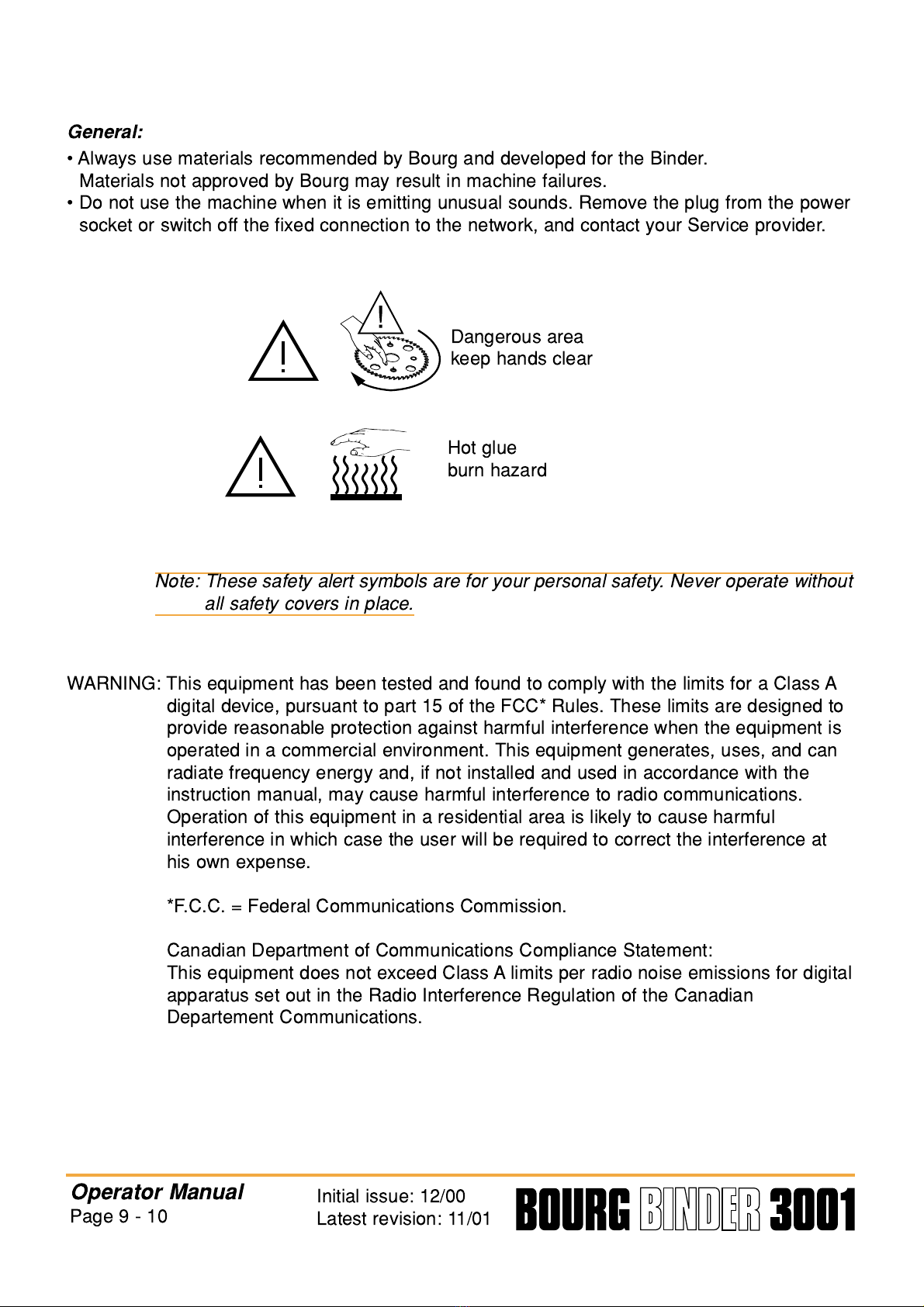
General:
• Always use materials recommended by Bourg and developed for the Binder.
Materials not approved by Bourg may result in machine failures.
• Do not use the machine when it is emitting unusual sounds. Remove the plug from the power
socket or switch off the fixed connection to the network, and contact your Service provider.
Dangerous area
keep hands clear
Hot glue
burn hazard
Note: These safety alert symbols are for your personal safety. Never operate without
all safety covers in place.
WARNIN : This equipment has been tested and found to comply with the limits for a Class A
digital device, pursuant to part 15 of the FCC* Rules. These limits are designed to
provide reasonable protection against harmful interference when the equipment is
operated in a commercial environment. This equipment generates, uses, and can
radiate frequency energy and, if not installed and used in accordance with the
instruction manual, may cause harmful interference to radio communications.
Operation of this equipment in a residential area is likely to cause harmful
interference in which case the user will be required to correct the interference at
his own expense.
*F.C.C. = Federal Communications Commission.
Canadian Department of Communications Compliance Statement:
This equipment does not exceed Class A limits per radio noise emissions for digital
apparatus set out in the Radio Interference Regulation of the Canadian
Departement Communications.
Operator Manual
Page 9 - 10 Initial issue: 12/00
Latest revision: 11/01

1.5 Safety data sheet
Model
BB 3001
Description
lue binder
Max. process speed
Maximum 500 cycles/hour
Dimensions & Weight
Lenght: 1,88 m 6.17 ft
Width: 1,16 m (3.8 ft) (with the possibility to split machine to have 695 mm
(2.28 ft) width for narrow way)
Height: 1,06 m 3.48 ft
Weight: 400kg 882 lbs
Voltage
208V/220V/230V/240V/3 220V/230V/240V/3 380V/400V/415V/3 N
Frequency
60 Hz 50 Hz 50 Hz
Current, rated
20 A 20 A 20 A
Power consumption, stand by
1500 W
Power consumption, operation
3000 W
Power consumption, maximum
5500 W
Mains connection
Cable with fixed connection and separation switch
Safety class
I (IEC 536) Protective earth connection
Protection class
IP 20 (IEC 529)
Sound pressure level
Standby In operation
Operator position
55 db(A) 76 db(A)
Radio interference
Complies with Directive 89/336/EEC
Radiation
Not applicable
Radiant heat
10224 Btu/hour
Ozone emission
Not applicable
Room volume
Recommendation: 95 m3(7 x 4,5 x 3 m) 3336 ft3 (23x14.8x9.8 ft)
Room ventilation
Recommendation: min. 47,5 m3/h (natural ventilation)
For heat evacuation at continuous binding extra ventilation may be necessary
Dust concentration
0,04 mg/m3at continous operation
(TLV for nuisance dust = 10 mg/m3)
Additionnal safety information
To avoid higher sound pressure levels than given above, the machine
should be installed in a room with at least minimum room volume (see
above) and favourable acoustical properties.
Operator Manual
Page 9 - 11 Initial issue: 12/00
Latest revision: 11/01
®
MODEL
SER. N
°
:
:
BB3001
3P+PE 60 Hz 208 / 220 / 230 / 240 V
20 A
LISTED
I.T.E.
E125337 MADE IN BELGIUM BY
c p bourg
S.A.
B-1340 Ottignies - rue des Technologies, 22
Tel : +32 / 10 / 62 22 11 Fax : +32 / 10 / 61 36 38
3P+PE 50 Hz 220 / 230 / 240 V
20 A
3P+N+PE 50 Hz 380 / 400 / 415 V
20 A
9139560
gepr
u¨
fte
Sicherheit
Refer to specifications
in Installation Manual.

2. SYSTEM DESCRIPTIO
2.1 Specifications
Book
Dimensions (max - min) See the illustration above
Cover types lossy paper, with cutouts, with transparent front, “kromekote”, etc.
Cover weight 80-250 gsm (may require creasing) 30-90 lb cover
Paper weight 60-160 gsm 15-40 lb bond
Features
Cover pile height 60 mm 2.4 in.
Miss detector Yes
Speed max. up to 500 cycles/hour.
lue temperature From 140° C to 165° C (284°F to 392°F)
Milling + notching Yes
Paper waste collection Yes
Book counter Yes
Start up timer optional
Fume extractor
with active charcoal filter optional
Outdoor fume exhaust optional
Ma hine
Dimensions: (l x w x h) 1,88 m x 1,16 m x 1,06 m (6.17 ft x 3.8 ft x 3.48ft)
Weight
Binder 400 kg (882 lbs)
Output Unit (optional) 55 kg (121 lbs)
Electrical supply 208V/220V/230V/240V (60Hz)
∆
-20A
220V/230V/240V (50Hz)
∆
-20A
380V/400V/415V (50Hz) Y -20A
Radiant heat 10224 Btu/hour
Noise level (Lpa) 76 dB (A) (at operator position)
Operator Manual
Page 9 - 12 Initial issue: 12/00
Latest revision: 11/01
320mm
(12.6in.)
385mm
(15.2in.)
100mm
(3.9in.)
100mm
(3.9in.)
140mm
(5.5in.)
210mm
(8.3in.)
Max.thickness
45mm
(1.8in.)
MAX. BOOK DIMENSIONS MIN. BOOK DIMENSIONS
•
With manual reception
•
With automatic reception
90mm
(3.5in.)
75mm
(2.95in.)
•
Padding mode
(without BBR - with manual
reception and only by the low exit)
Min. thickness:
2 sheets (theorecal,
with very thin cover)
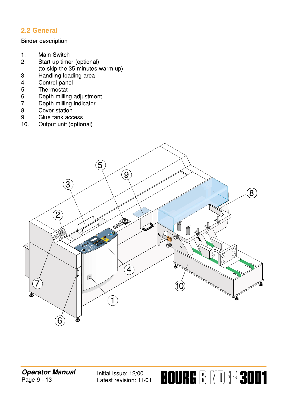
2.2 General
Binder description
1. Main Switch
2. Start up timer (optional)
(to skip the 35 minutes warm up)
3. Handling loading area
4. Control panel
5. Thermostat
6. Depth milling adjustment
7. Depth milling indicator
8. Cover station
9. lue tank access
10. Output unit (optional)
Operator Manual
Page 9 - 13 Initial issue: 12/00
Latest revision: 11/01
EMERGENCY
STOP
NOTSTOP
ARRET
D'URGENCE
NOODSTOP
GLUE TEMPERATURE CONTROL
LEIMTEMPERATURREGULIERUNG
REGULATION
TEMPERATURE
COLLE
LI MTEMPERATUURSTURING
9
2
1
4
6
10
7
3
5
8

2.3 Control Panel
1. Closes the carriage and starts the Binding Process
(press the two start buttons simultaneously)
2. Adjusts the clamping duration
3. Adjusts the lateral clamping pressure
4. Adjusts the suction level
5. Allows you to select menus and perform operation from these menus
6. Toggles the blade rotation ON/OFF
7. Selects the programs*
8. Toggles the glue tank heating (the drum rotation starts when the glue is warm enough)
9. Confirms the selection
10. Stop all operations in an emergency
11. Opens the carriage
12. Toggles jogger ON/OFF
13. Carriage normal or large pre-opening
14. Fixed speed ON/OFF
15. Liquid Crystal Display for menus and messages
*
With cover
or Without cover evacuation:top (for padding)
or Without cover evacuation:bottom (for padding)
Stop the drum rotation to select the program.
Confirm the choice by starting the drum rotation.
Note: In N 1 mode with pre-feed : yes. If the message “Cover sheet misfeed” is
displayed, it is not possible to change the program.
ou have to press on the emergency button and then change the program.
Operator Manual
Page 9 - 14 Initial issue: 12/00
Latest revision: 11/01
1
2
3
4
56
7
8
9
10
S.A .
N.V .
c p bourg
ENTER
MENU
PROGR.
1 2 3 4 6 7 8 10 11 1
1312 14 15
5 9

2.4 Control panel menus and messages
Operator Manual
Page 9 - 15 Initial issue: 12/00
Latest revision: 11/01
1
2
3
4
56
7
8
9
10
S.A .
N.V.
c p bourg
ENTER
MENU
PROGR.
MENU
MENU
MENU
MENU
MENU
MENU
Display of the values
previously selected in
next two menu steps.
At switch on:
CHANGE TOTAL NUMBER
O
N
F B I ND I NGS
R . OF B I ND I NGS :
COUNTER RESET
GLUE F I LM LENGTH
±
7
±
16
EX TRA CORRECT I ON
COVER POS I
T I ON
OVERLAP (
mm
) : XXX
1
–
>N
L
: CORR :
NR .
.
OF B I ND I NGS : X
XXX
:
BOOK S I ZE :
S I ZE CO ER T I ON :
OM DE 1
–
>N
E
RP E - F ED :
C
LANGU : (
FGB D
NL I E P
)
R
XXX
List of messages and instructions:
• Emergency pressed or hood not
closed
• Reset
• Drum is heating but is still too cold.
• Problem with book in delivery area
• Lift perpex guard remove cover if any
• Press key drum to start heating
• Remove paper from binder if any
• Cover feeder did not move
• Binder is in test mode
• Spine is drying
• Depress both green push buttons
• Cover sheet misfeed
• Milling motor is overheated
• Switch off and open hood
• Binding in progress
• Problems with carriage position
• Remove cover sheet
• Heating is disabled.
Push key to restore
• Delivery conveyer
Not ready / connected
• Replace MCU battery
• lue temperature too high
• Replace dust bag
• Binder is ready
• Open carriage and remove book
ERROR MESSAGES
1 Carriage open/close
Motor problem M7 F35
2 Shutter motor
Problem M15 F5
4
Cover nipping motor
Problem - M14 (F12)
8
Suction bar problem
Up/down motor M13 (F4)
9 Clutch or brake problem
K12 (F2)
10 T21 Time out/process longer
than one min
17 Notching tools index
probl.
18 Error check S45
S49 and Tacho
19 Book too thick or
carr switch probl
messages # on (earlier) eprom
#

2.5 Change of binding parameters
Operator Manual
Page 9 - 16 Initial issue: 12/00
Latest revision: 11/01
no
yes
CYCLE RUN
yes
no
Mode and parameters
are correct
MENU
MENU
Mode is
correct
+ENTER
yes
no
Book size
is correct
yes
+ENTER
no
yes
+ENTER
yes
no
Is cover leading edge
flush with book ?
+ENTER
MENU
MENU
MENU
MENU
ENTER
+
Pre-feed
is correct no
Press on both green buttons
ENTER
MENU
START
Press on button
Changes the
screen
Selects the
desired line
Changes the
parameters
Confirms the
selected
parameters
MENU
+
ENTER
B I NDER READY
1
–
>N
W
: X XX
XX XXX CORR :
NR . OF B I ND I NGS :
:
BOOK
PRE - FEED
S I ZE :
S I Z E CORRECT I ON :
OM DE N
–
>1
:
BOOK S I Z E :
S I Z E CORRECT I ON :
OM DE
-:
N
–
> 1
:
BOOK S I Z E :
S I Z E CORRECT I ON :
OM DE N
–
>1
Book length
is correct
:
BOOK S I Z E :
S I Z E CORRECT I ON :
OM DE N
–
>1
EXTRA CORRECT I ON
COVER POS I T I ON
OVERL
A
P (
mm
) : XXX
Realign
(each push = 0.2 mm)
E
RP E F E D
-:
E
RP E F E D
-:
E
RP E F E D

Operator Manual
Page 9 - 17 Initial issue: 12/00
Latest revision: 11/01
MENU
MENU
MENU
MENU
no
The right end of
glue film is correct
yes
+ENTER
no
Inhibition cylinder
state is correct
yes
+ENTER
yes
no
+ENTER
yes
no
The language
is correct
ENTER
+ENTER
The left end of
glue film is correct
yes
no
±
I N H I B I T I O N C Y L . 1 :
yes
no
ENTER
MENU
MENU
MENU
MENU
MENU
MENU
MENU
GLUE FILM LENGTH.
±
7
±
16
XXX
:
GLUE F ILM LENGTH.
± ±
16
7
XXX
:
:
GLUE F ILM LENGTH
Number of bindings
is correct
CHANGE TOTAL NUMBER
O
N
FBI NDI NGSxxx
R.OF B I ND I NGS
COUNT ERRESE T:x x x
Reset of
the counter
CHANGE TOTAL NUMBER
O
N
FB I NDI NGSxxx
R.OF B I ND INGS :
COUNT ERRESET
LANGU : (
FGBD
NL I E P
)
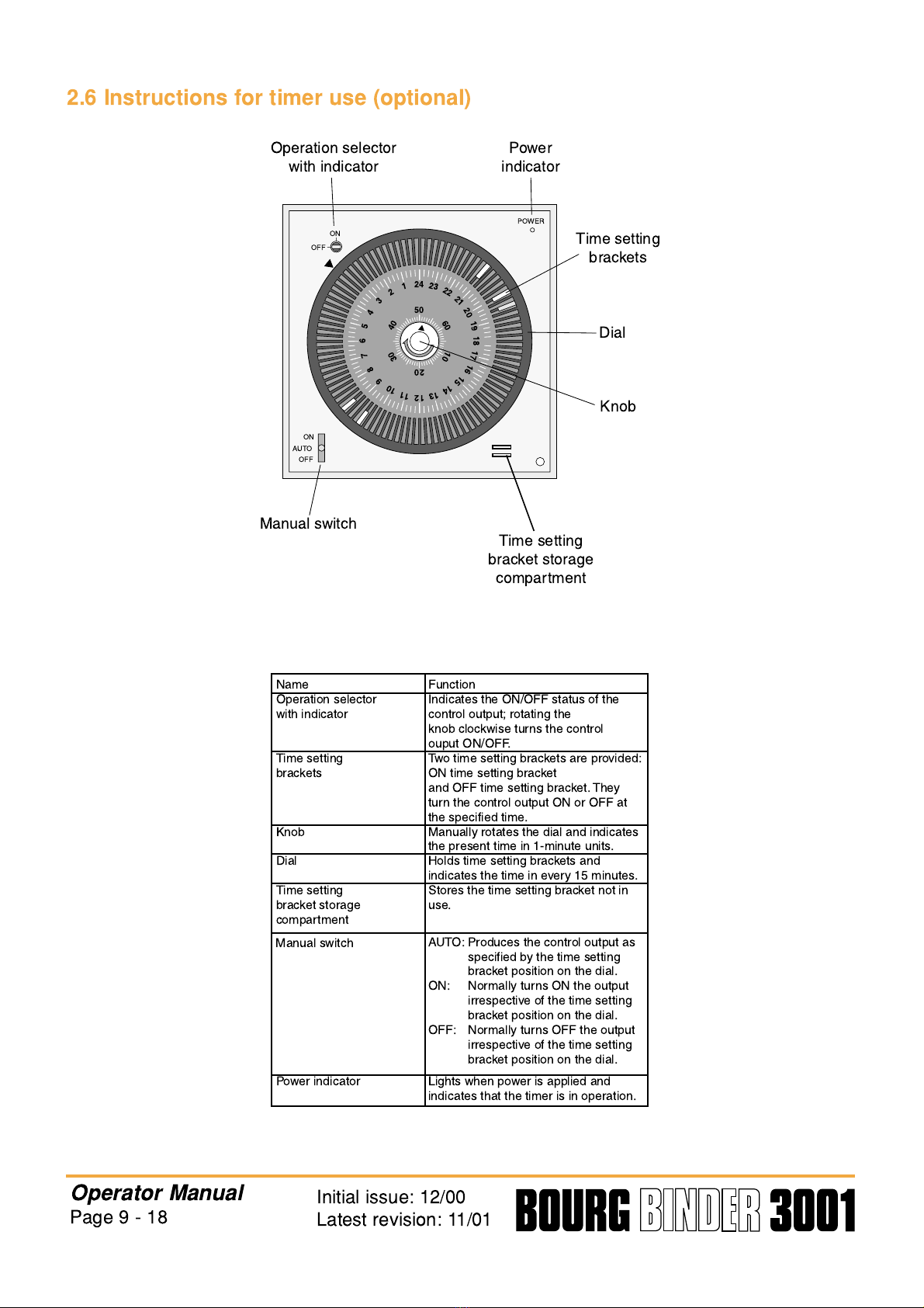
2.6 Instructions for timer use (optional)
Operator Manual
Page 9 - 18 Initial issue: 12/00
Latest revision: 11/01
24
50
40
30
20
10
60
1
2
3
4
5
6
7
8
9
10
11
12
13
14
15
16
17
18
19
20
21
22
23
ON
POWER
ON
AUTO
OFF
OFF
Operation selector
with indicator Power
indicator
Time setting
brackets
Dial
Knob
Time setting
bracket storage
compartment
Manual switch
Name
Operation selector
with indicator
Time setting
brackets
Knob
Dial
Time setting
bracket storage
compartment
Power indicator
Function
Indicates the ON/OFF status of the
control output; rotating the
knob clockwise turns the control
ouput ON/OFF.
Two time setting brackets are provided:
ON time setting bracket
and OFF time setting bracket. They
turn the control output ON or OFF at
the specified time.
Manually rotates the dial and indicates
the present time in 1-minute units.
Holds time setting brackets and
indicates the time in every 15 minutes.
Stores the time setting bracket not in
use.
Lights when power is applied and
indicates that the timer is in operation.
Manual switch AUTO: Produces the control output as
specified by the time setting
bracket position on the dial.
ON: Normally turns ON the output
irrespective of the time setting
bracket position on the dial.
OFF: Normally turns OFF the output
irrespective of the time setting
bracket position on the dial.

Settings
1. Remove the transparent cover from the front panel.
2. Rotate the center knob in the arrow direction (i.e., clockwise) to set the time. The present
time can be set in 1-minute units. For example 3:50 as shown in the figure. Do not rotate
the knob counterclockwise.
3. Two time setting brackets are provided: ON (gold) and OFF (silver). Be sure to use the
correct bracket and securely insert it in the groove of the dial.
4. Alternately set the ON and OFF time setting brackets.
5. After setting the time, reattach the transparent cover to the front panel.
Operation
6. Firmly insert the ON/OFF time setting bracket to the desired time setting groove. However,
do not insert it in a groove within ± 15 minutes distance from the dial groove that indicates
the present time.
7. After the time setting bracket is fixed and with the power and load connected to the timer,
rotate the knob in the arrow direction. Turn the dial one complete rotation to check if the
control output is turned ON/OFF in accordance wit the setting of the time setting bracket on
the dial.
8. Rotate the knob in the arrow direction and set the desired time according to step 2.
Operator Manual
Page 9 - 19 Initial issue: 12/00
Latest revision: 11/01
24
50
40
30
20
10
60
1
2
3
4
5
6
7
8
9
10
11
12
13
14
15
16
17
18
19
20
21
22
23
ON
PO ER
ON
AUTO
OFF
OFF
3 o'clock
50 minutes

9. Now start the operation of the timer.
Example:
With the above setting the timing chart will be as follows:
Operator Manual
Page 9 - 20 Initial issue: 12/00
Latest revision: 11/01
24
50
40
30
20
10
60
1
2
3
4
5
6
7
8
9
10
11
12
13
14
15
16
17
18
19
20
21
22
23
ON
OFF
OFF
ON
ON
ON
OFF
OFF
24 1 2 3 4 5 6 7 8 9 10 11 12 13 14 15 16 17 18 19 20 21 22 23
This manual suits for next models
1
Table of contents
Other C.P.Bourg Binding Machine manuals


