C.P.Bourg Document Finisher E Series User manual

OPERATOR
MANUAL
Initial issue: 02/13
Latest revision : -
9.133.347

Operator Manual
Page 9 - 2 Initial issue: 02/13
Latest revision: -
Content of this documentation has a confidential nature and remains
the exclusive property of c.p. bourg s.a. It is only put at the user
(including without limitation: Renter or Purchaser or their employees)
disposal within the exclusive scope of using and servicing the product.
Without c.p. bourg s.a. prior agreement in writing, disclosure to
third party and/or reproductions as well as changes are prohibited.

Operator Manual
Page 9 - 3 Initial issue: 02/13
Latest revision: -
TABLE OF CONTENTS
1. Important.............................................................................................. 6
2. Warnings .............................................................................................. 7
2.1 Prior to the installation.................................................................................... 7
3. Introduction ......................................................................................... 8
3.1 Foreword ....................................................................................................... 8
3.2 Job Definition Format (JDF) Capability ......................................................... 9
4. Warning pictograms............................................................................ 10
5. Pictogram location.............................................................................. 13
5.1 Front View ...................................................................................................... 13
5.2 Rear VIew....................................................................................................... 13
6. Machine description............................................................................ 14
6.1 Technical features .......................................................................................... 14
6.1.1 General : .................................................14
6.1.2 Stitcher : .................................................14
6.1.3 Folder : ..................................................14
6.1.4 Trimmer : .................................................15
6.1.5 Conveyor : ................................................15
6.2 Job specifications ........................................................................................... 16
6.3 Stitching system description........................................................................... 18
6.4 Stitching possibilities with Jogger Type 0....................................................... 19
7. Process description............................................................................ 24
8. Connecting the machine to mains .................................................... 25
8.1 Stitching head adjustment .............................................................................. 26
8.1.1 Stitching heads mechanical unclutching ........................26
8.1.2 Stitching wire length adjustment ..............................27
8.1.3 Cassettes replacement with ISP M2000 heads ...................27
8.1.4 Wire spool replacement (for Hohner 43/6 S heads) ...............30
8.1.5 Wire jam in the stitching head ................................31
9. The User Interface (U.I.) screens ....................................................... 32
10. Screen functions in detail ................................................................ 33
10.1 U.I. screen options........................................................................................ 33
10.1.1 U.I. screen Operator's preferences ...........................34
10.1.2 Machines line configuration .................................35
10.1.3 JDF Mode Selection .......................................40
10.1.4 File menu ...............................................41
10.2 BDF-e tab options......................................................................................... 42
10.2.1 Paper size and Stitcher parameters screen .....................43
10.2.2 Folding parameter ........................................45
10.2.3 Trimming parameter .......................................46

Operator Manual
Page 9 - 4 Initial issue: 02/13
Latest revision: -
10.2.4 Output conveyor parameter .................................47
10.2.5 File menu parameter ......................................48
10.2.6 Preferences Menu.........................................53
10.2.7 Manual stitching of a set ....................................54
10.2.8 Warning screen and error messages ..........................55
10.2.9 Counter of set ............................................56
10.2.10 U.I. version and update history .............................57
10.3 RUN tab options ........................................................................................... 58
10.3.1 BDF-e adjustment in RUN mode .............................59
10.4 List of errors.................................................................................................. 63
10.5 4 - Remedies ................................................................................................ 66
11. Preventive maintenance ................................................................... 68
12. Environmental compliance............................................................... 71
12.1 Product recycling and Disposal .................................................................... 71

Operator Manual
Page 9 - 5 Initial issue: 02/13
Latest revision: -
This page is intentionally left blank.

Operator Manual
Page 9 - 6 Initial issue: 02/13
Latest revision: -
1. IMPORTANT
F: Important
Cette machine ne peut fonctionner qu'avec toutes les sécurités au repos (capots) et tous les
accessoires (plateau de réception ou de transfert, convoyeur de sortie, conteneur déchets de
coupe) en place.
Attention: Garder les mains à l’écart des pièces en mouvement.
GB/US: Important
This machine will operate only with all the safety devices of the collating / finishing line deacti-
ved (guards) and delivery/transfer tray or conveyor waste container connected in working posi-
tion.
Caution: Keep hands clear of moving parts.
PT: Importante
Esta máquina apenas funcionará com todos os dispositivos de segurança da linha de separa-
ção/acabamento desactivados (protecções) e com o tabuleiro de saída/transferência ou o
compartimento de desperdícios do transportador ligados na posição de funcionamento.
Cuidado: Manter as mãos afastadas das peças móveis.
D: Wichtig
Diese Maschine kann nur in Betrieb genommen werden, wenn alle Sicherheitsvorrichtungen
der Verarbeitungsstrasse (Plexihauben, Notschalter, Empfangs oder Transfertplatte Auslage)
sich in Arbeitsposition befinden.
Achtung: Hände nicht in die Nähe laufender Maschinenteile bringen.
ESP: Importante
Esta máquina sólo se pondrá en funcionamiento cuando todos los dispositivos de seguridad
de la línea de clasificación / acabado estén desactivados (dispositivos protectores) y la bande-
ja de salida / transferencia o el contenedor de desechos de la transportadora estén conecta-
dos en la posición de funcionamiento.
Precaución: Mantenga las manos alejadas de las partes móviles.

Operator Manual
Page 9 - 7 Initial issue: 02/13
Latest revision: -
2. WARNINGS
2.1 Prior to the installation
Verify that your electrical mains corresponds with one of the following three networks:
USA 120V AC +/- 10% - 60Hz
EUROPE 230V AC +/- 10% - 50Hz
JAPAN 230V AC +/- 10% - 60Hz
THE LABEL APPLIED ON YOUR MACHINE INDICATES FOR WHICH MAINS
THE MACHINE IS CABLED.
Verify your environmental conditions.
This machine is planned for the following environment:
Storage and transport::
Temperature: -34°C through 60°C : -30°F through 140°F
Relative humidity: 5 through 90% RH
Altitude: -31 m through 12 192 m / -100st through 4000st
Atmospheric pressure: ≥ 56Pa (420mm HG)
Work environment:
Temperature: 10°C through 32°C
Relative humidity: 10 through 85% RH
Consumption: 750 Watt
Noise level: 70 db
WARNING: Never remove wall plug when the machine is running.

Operator Manual
Page 9 - 8 Initial issue: 02/13
Latest revision: -
3. INTRODUCTION
3.1 Foreword
Thank you for choosing a c.p. bourg product.
This manual is a guide to operate the Bourg Document Finisher E-Series.
The BOURG DOCUMENT FINISHER E-Series (BDF-e) is an automatic machine for the pro-
duction of books; it staples, folds and face trim sets originating from, a printer or a press
machine.
The system is composed of:
- Input module,
- Stitcher, folder and trimmer module,
- Output conveyor.
Please follow carefully the instructions and you will enjoy years of excellent work with your system.
If you have any difficulty using your equipment, please call us and ask for technical assistance
(all the phone numbers are available at the end of this manual).
We will be delighted to help you.
All the information in this publication is based on the latest information available at the time of
approval for printing.
We reserve the right to revise this publication and to make changes in the content without
obligation to notify such revision or changes.
THIS MANUAL IS INTENDED TO BE USED EXCLUSIVELY BY QUALIFIED PERSONNEL

Operator Manual
Page 9 - 9 Initial issue: 02/13
Latest revision: -
3.2 Job Definition Format (JDF) Capability
A new Web to Finish solution makes touch less workflow achievable from order to finished pro-
duct with no manual setup or intervention; thus, helping automatic print production by giving
the finishing devices an integral role in the manufacturing process.
Integrating finishing equipment capabilities into the job definition at the prepress stage reduces
or eliminates operator involvement and reduces or eliminates job setup time.
A new device, the called Bourg Box, allows BDF-e to communicate with any type of digital
printer.
The WorkFlow Manager (WFM) embedded in BDF-e GUI allows the
BDF-e of a BB/
BDF-e configuration, to be set up for jobs and service using the BDF-e GUI.
The WFM uses a digital job ticket to set up the finishing equipment automatically.
Note: The optional SQE (Square Edge Module) does not feature the automatic setup
capability.
The job ticket is an XML based file format standard for information exchange in the graphic
arts environment.
The JMF (Job Message Format) synchronization between Ultimate Bindery and the Bourg
finisher informs Ultimate Bindery of the finisher status. When the finisher is ready, Ultimate
Bindery releases the job at the FFPS queue and the job is printed and finished.
Note: - JDF mode is only enabled with the optional Bourg JDF Kit.
FreeFlow Web
Services
FreeFlow Process
Manager
1
Free Flow Connect
OnDemand Digital
2
Ultimate Bindery
3
FreeFlow
Print Server
4
Press
5
BDF-eGUI
6
Bourg Box
7
JDF instructions and PDF file via JMF
PDF File via Hot Folder
Release job via IPP
DFA level 1
CAN BIP
CAN BIP
Imposed PDF is
submitted via IPP
FFPS returns Job ID
Finishing setup info
passed in JDF via JMF
Solution Workflow Diagram

Operator Manual
Page 9 - 10 Initial issue: 02/13
Latest revision: -
4. WARNING PICTOGRAMS
Note: The BDF-e is equipped by a touch screen and this screen contains a battery Danger
of explosion if battery is wrongly replaced. Replace only with the same or equivalent
type recommended by the manufacturer Dispose of used batteries according to the
manufacturer's instructions. Please call for qualified technician to replace the battery.
Please pay attention to the following signs:
Caution:
on a yellow background,
indicates a hazardous situation that can cause small or severe injury.
Warning:
on a orange background,
is used to indicate a hazardous situation which has some probability of death or severe
injury.
Warning should not be considered for property damage accidents unless personal injury
risk is present.
Danger:
on a red background,
indicates a hazardous situation with a high risk of death or severe injury. The ‘danger’
sign does not apply to accidents causing material damage, unless they can cause
personal injury.
WARNING
HAZARDOUS VOLTAGE
CAN CAUSE SEVERE
INJURY OR DEATH
This label is located near the main power unit. It warns of a high risk
of electrocution when opening the power supply box with a risk of
severe injury or death.

Operator Manual
Page 9 - 11 Initial issue: 02/13
Latest revision: -
CAUTION
CAUTION
KEEP HANDS CLEAR
DO NOT OPERATE
WITHOUT SAFETY
COVERS IN PLACE
CAUTION
Crush hazard
Machine may move
when changing
paper size.
Stay clear of this
area.
WARNING
KEEP HANDS CLEAR
CAN CAUSE
SEVERE INJURY
This label is located near the wheel-work of the chain. It indicates
a high risk of injury to your fingers if they get stuck between the
wheel-work and the chain.
This label is located on the centering plate.
This label is located near the knife of the
folding machine. It warns of a high risk of
severe hand injuries when placing your
hands under the knife.
This label is located near the knife of the press-cutter. It indicates a high
risk of severe injury if you put you hands under the knife.
This label is located near the stapling head. It indicates a high risk of
severe injury to your fingers if you place them under this head.

Operator Manual
Page 9 - 12 Initial issue: 02/13
Latest revision: -
CAUTION
DO NOT OPERATE
WITHOUT SAFETY
COVERS IN PLACE
CAUTION
ELECTRICAL HAZARD
AUTHORIZED SERVICE
PERSONNEL ONLY
CAUTION
PINCH POINTS
KEEP HANDS CLEAR
This label is located near the primary shaft.
It indicates a high risk of severe injury to
your fingers if they get stuck in the belt.
This label is located near the main power
supply. It indicates that this power supply
cabinet may only be opened by qualified
personnel.
This label is located at the rear of the machine under the safety cover.
It indicates that the machine may not be operated, under no circums-
tances, without the safety covers being in place.

Operator Manual
Page 9 - 13 Initial issue: 02/13
Latest revision: -
5. PICTOGRAM LOCATION
5.1 Front View
CAUTION
S98s
WARNING
HAZARDOUSVOLTAGE
CANCAUSESEVERE
INJURYORDEATH
CAUTION
CAUTION
DO NOT OPERATE
WITHOUT SAFETY
COVERS IN PLACE
CAUTION
DO NOT OPERATE
WITHOUT SAFETY
COVERS IN PLACE
CAUTION
KEEPHANDSCLEAR
DONOT OPERATE
WITHOUTSAFETY
COVERSINPLACE
WARNING
HAZARDOUSVOLTAGE
CANCAUSE SEVERE
INJURYOR DEATH
CAUTION
DO NOT OPERATE
WITHOUT SAFETY
COVERS IN PLACE
CAUTION
PINCH POINTS
KEEP HANDS CLEAR
WARNING
HAZARDOUS VOLTAGE
CAN CAUSE SEVERE
INJURY OR DEATH
CAUTION
KEEP HANDS CLEAR
DO NOT OPERATE
WITHOUT SAFETY
COVERS IN PLACE
WARNING
KEEP HANDS CLEAR
CAN CAUSE
SEVERE INJURY
S98s
CAUTION
CAUTION
DO NOT OPERATE
WITHOUT SAFETY
COVERS IN PLACE
CAUTION
KEEP HANDS CLEAR
DO NOT OPERATE
WITHOUT SAFETY
COVERS IN PLACE
CAUTION
CAUTION
PINCH POINTS
KEEP HANDS CLEAR
WARNING
HAZARDOUS VOLTAGE
CAN CAUSE SEVERE
INJURY OR DEATH
5.2 Rear VIew
Operator Manual
Page 9 - 14 Initial issue: 02/13
Latest revision: -
6. MACHINE DESCRIPTION
6.1 Technical features
6.1.1 General :
- Height of input / exit: 860mm.
- Fully automatic adjustment depending on the format.
- By-pass of the folder and trimmer for the production of top stitched brochures.
- Detection of any «jam» or open baffles or covers on the paper path.
- Detection of conveyor or chip container full.
6.1.2 Stitcher :
- The BDF-e may be operated with 1, 2 and 4 stitching heads (factory install configura-
tion) and deactivated.
- Automatic adjustments for paper size and stitch location.
- Automatic motion and adjustment of the stitching heads.
- Model equipped with ISP stitching heads: toolless change over self threading cassette
for stitch wire supply.
- Stitcher may, as a factory deliverable option, be equipped with Hohner stitching heads
(2-4 heads).
- Hohner heads convertible to loop stitch model via upgrade kit.
- Missing stitch detection.
6.1.3 Folder :
- Motorized system for roller spacing.
- Automatic adjustment of the stops.
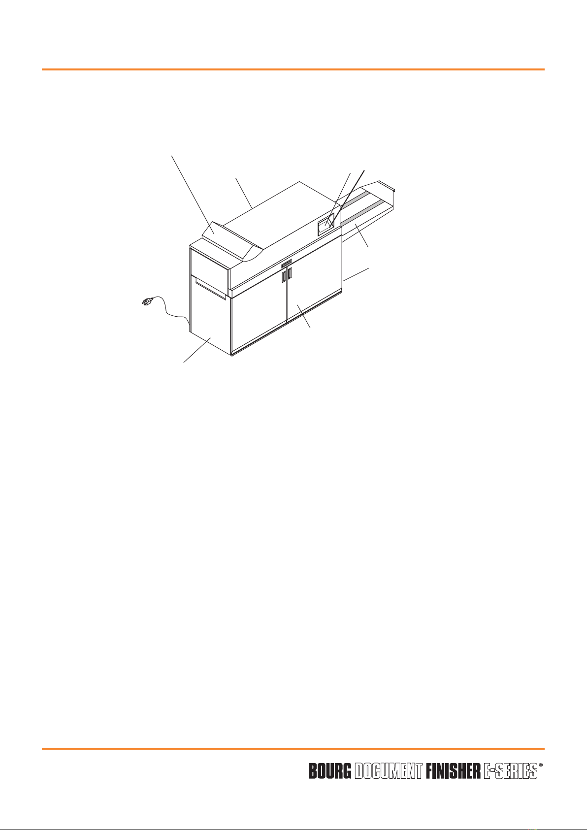
Rear of the machine
Front of the machine
Upper cover
Exit conveyor
Right side (operator) of
the machine
Left side of the machine
Input of the machine
GUI screen

Operator Manual
Page 9 - 15 Initial issue: 02/13
Latest revision: -
6.1.4 Trimmer :
- Paper chips ejected to waste container, with “full” condition sensor.
- Automatic adjustment of the stops.
6.1.5 Conveyor :
- Adjustment of the conveyor steps via operator’s GUI.

Operator Manual
Page 9 - 16 Initial issue: 02/13
Latest revision: -
6.2 Job specifications
Note: The figures below represent what the BDF-e is capable of producing.
The device feeding paper to the BDF-e may alter those specifications.
Type of paper :
Any type of paper except paper with a window and transparent paper.
• Coated / uncoated (60 - 200gsm) (16 lb bond - 110 lb index).
• Cover : 80 - 300gsm (20 lb bond - 10 pt cover stock).
Paper size :
Min = 203mm (8")
Max = 520mm (20.5")
Min = jog 0 : 127mm
(5")
jog 1 : 134mm
(5.3")
Max = 356mm (14")
Min = jog 0 : 127mm
(5")
jog 1 : 134mm
(5.3")
Max = 356mm (14")
Min = 101mm (4")
Max = 260mm (10.25")
Min = jog 0 : 127mm (5")
jog 1 : 134mm (5.3")
Max = 356mm (14")
Min = 160mm (6.3")
Max = 297mm (11.7")
Max. trim =20mm (0.8")
Saddle stitching
For “Jog 0” and “Jog 1” description,
see “3-Stitching system description”.
Top/Side stitching
Folding/Trimming

Operator Manual
Page 9 - 17 Initial issue: 02/13
Latest revision: -
Book thickness :
Saddle stitching (stitches in the middle of the paper sheets, then fold and trim) :
- between 2 and 22 sheets of 80gsm (20 Lbs bond) or equivalent thickness (cover included).
Corner or top stitching:
- between 2 to 55 paper sheets of 80gsm (20Lbs bond) or equivalent thickness (cover
included).
Number of sets per hour :
- Stitching only:
- Stitching and folding :
- Stitching, folding and trimming :
Input speed of the machine :
500 mm/s to 1280 mm/s.
Stitcher limits:
See “Stitching system description” further.
Folder :
Automatic spacing of the rollers :
Theorical values.
Trimmer :
Length of the cut.
Capacity of chip container: cuts from 8000 sheets of 80 gsm (20Lb bond) with a 5 mm cut.
Conveyor :
Motion step.
Capacity : 42 sets of A4 (8x10) size composed of 10 sheets of 80gsm (20lb bond).
Min. 0.25 mm (9.8 mil.) Pos. # 1
Max. 4 mm (0.16 in.) Pos. # 10
Default value 0.4 mm (5.7 mil.) Pos. # 2
Depending on the quantity of sheets per set
and the parameters setted in the
downstream machines (see install manual).
Min. 0 mm (0 in.)
Max. 20 mm (0.8 in.)
Standard 5 mm (0.2 in.)
Min. +/- 6 mm (+/- 0.2") position 1
Max. +/- 180 mm (+/- 7") position 30
Default value +/-48 mm (+/- 1.9") position 8

Operator Manual
Page 9 - 18 Initial issue: 02/13
Latest revision: -
6.3 Stitching system description
Side joggers type
One type of side jogger is used:
- type 0, with cut-out.
Joggers type 0.
LH RH

Operator Manual
Page 9 - 19 Initial issue: 02/13
Latest revision: -
6.4 Stitching possibilities with Jogger Type 0
Illustration 1 : Corner stitch with Jogger Type 0
Paper width 127 mm (5") to
187 mm (7.3")
187 mm (7.3")
to 270 mm (10.6")
270 mm (10.6")
to 356 mm (14")
Machine Type Stitch
position
2 heads on 2
bracket heads
2 saddle or
top
Space between stitches = 80 mm (3.1") to paper width - 30 mm (1.2")
1 corner YES (left or right)
4 heads on 4
bracket heads*
4 saddle or
top Not possible
"Space between stitches
=
80 mm (3.1") to 166 mm
(6.4")" (middle heads)
1 corner YES (left or right
middle brackets**) Not possible YES (left or right outside
brackets**)
2 heads on 4
bracket heads
2 saddle or
top
"Space between stitches =
80 mm (3.1") to 166 mm (6.4")"
(middle heads)
"Space between stitches
=
240 mm (9.4") to paper
width - 30 mm (1.2")
(outside heads)"
1 corner YES (left or right
middle head) Not possible YES (left or right outside
heads **)
* Requires installation of heads on proper brackets (middle or outside ones)
** Stitching head position at installation
15mm
7mm

Operator Manual
Page 9 - 20 Initial issue: 02/13
Latest revision: -
How to use these chart
In this case, if the width of the sheet is between 127 and 356mm, spacing staples will be
between 80 and 326mm
Then stitching with BDF 2H on 2brackets
with jogger type 0is possible
Authorized work area
For example: X
A sheet of width 250mm (W) allows a gap for the stitchers (E) between 80 and 220mm, in
this case 130mm
This manual suits for next models
1
Table of contents
Popular Industrial Equipment manuals by other brands


Vortec
Vortec 921 Series Operation & Safety Instructions

Siemens
Siemens 3VT9100-8LA00 operating instructions

ABB
ABB ACS880 Series Electrical Planning Guide

ABB
ABB HT846804 Operation manual

Schmalz
Schmalz SSP operating manual

Unitary products group
Unitary products group P XU-V/G9V-UP Series installation manual