Delta Visione DEV7 User manual
DEV7 Rel.4.1 27.12.2017
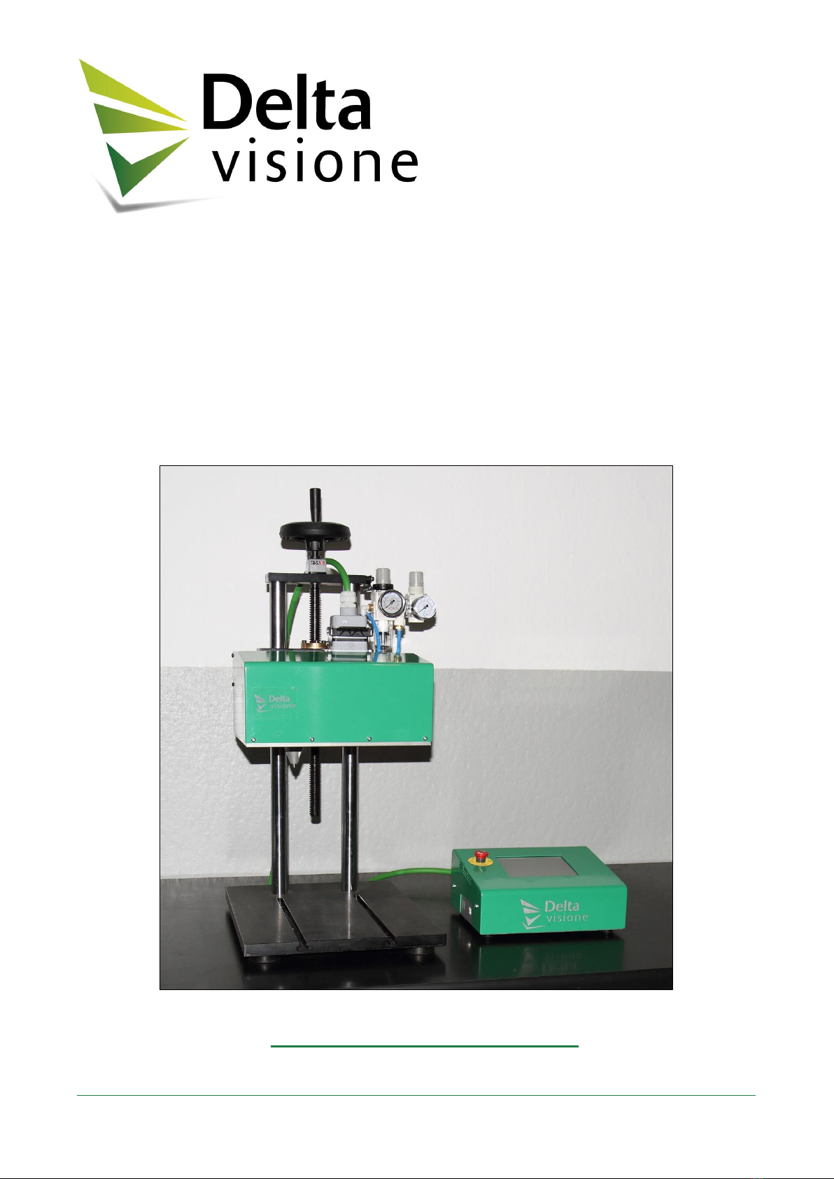
MarkingSystem
DEV7
Useandmaintenancemanual


DEV7 –Use and Maintenance Manual
Pag. 1
Preface
Scope of the document
This manual is a guide for the users and maintenance personnel of the DEV7 Marking System.
This instructions manual relates to a machine designed exclusively for professional use. Simply reading
this manual is not a substitute for experience and, in order for the machine to be correctly operated, it
should be operated by appropriately trained personnel. Although extreme care has been taken in the
collection and verification of these documents, DELTA VISIONE does not accept responsibility for
any imprecision or omissions, nor for the manner in which the operator uses the information
contained in this manual.
The operating manual should be referred to in order to start up the machine, to operate the machine and
to maintain the safety measures. The manual aims to:
1. Reduce the time that the machine is off-line and limit the need to request the manufacturer for
assistance
2. Guarantee that the system runs smoothly by providing complete and detailed instructions
3. Eliminate any risks connected to the use of the machine.
The operator should carefully read all the instructions in this manual and keep it for later reference. The
manual should be retained for future reference.
All the rights related to the text, images and documentation present in this manual are reserved: any
reproduction of its whole or parts is prohibited without the written permission of DELTA VISIONE.
The company can be contacted with requests for copies or updates of the manual.
DELTA VISIONE reserves the right to carry out variation in production and in the manual without
warning and without being obliged to update previously produced machines and the preceding manuals.
This manual should be considered an integral part of the machine and should therefore be
retained for reference until such a time as the machine is dismantled.

DEV7 –Use and Maintenance Manual
Pag. 2
Summary
1Identification..................................................................................................... 5
Identification of the maker...................................................................................................................5
Identification of the machine...............................................................................................................5
Intended use ........................................................................................................................................6
Compliance to safety regulations.............................................................................................7
Personnel training.....................................................................................................................7
Stand-alone...............................................................................................................................7
Maintenance service............................................................................................................................ 8
CE Labels........................................................................................................................................... 10
2Description and characteristics.................................................................... 11
General description............................................................................................................................ 11
Marking head..................................................................................................................................... 12
Control unit......................................................................................................................................... 14
E-Stop button .......................................................................................................................... 16
Touch-screen .......................................................................................................................... 17
3Installation ...................................................................................................... 19
Transport............................................................................................................................................ 20
Installation.......................................................................................................................................... 20
Connections....................................................................................................................................... 20
Electrical connection............................................................................................................... 20
Pneumatic connection............................................................................................................ 20
Integration.......................................................................................................................................... 21
Lighting............................................................................................................................................... 21
Protective devices.............................................................................................................................. 21
Noise................................................................................................................................................... 21
Stand-alone operation............................................................................................................ 22
Putting the machine into operation................................................................................................... 23
Operational faults............................................................................................................................... 24
4Residual risks................................................................................................. 25
5Commands and signals................................................................................. 27
6Ordinary maintenance.................................................................................... 29
Prerequisites and cautions................................................................................................................ 29
General............................................................................................................................................... 30
General rules........................................................................................................................... 30
Utensils, tools and materials.................................................................................................. 30
Maintenance interventions general plan.......................................................................................... 31
Safety –General rules............................................................................................................ 31
Maintenance plan.................................................................................................................... 32
Attachment 1 I/O Signals ..................................................................................... 35
Connector CN2 –Output................................................................................................................... 35
Connector CN2 –Input...................................................................................................................... 36
Connector CN2 –Emergency management.................................................................................... 36
Attachment 2 Pneumatic diagram....................................................................... 37

DEV7 –Use and Maintenance Manual
Pag. 3
Attachment 3 Technical specifications .............................................................. 39
Mechanical specifications ................................................................................................................. 39
Electrical specifications..................................................................................................................... 39
Pneumatic specifications................................................................................................................... 39
Attachment 4 Exploded-view drawings of the transmission............................ 41
Attachment 5 Exploded-view drawings of punches.......................................... 45


DEV7 –Use and Maintenance Manual
Pag. 5
1 Identification
Identification of the maker
For any problem related to the operation of the machine arising during and after the warranty period,
please refer to the maintenance and service department of:
DELTA VISIONE s.r.l.
a socio unico
Via Carlo Spegazzini, n° 4
10010 Bairo (TO)
Tel. +39 0124 50 18 58
Fax. +39 0124 50 18 57
E-mail: support@deltavisione.com
Web: www.deltavisione.com
C.F. e P.IVA: 09403750012 - R.E.A.: TO 1049465 - Cap. Soc.: € 75.000,00 i.v.
Identification of the machine
Product type: Scribe Marking Machine
Machine code: DEV7
The DEV7 scribing unit is a registered “CE” machine, built in accordance with the norms of the
European Community, as described in the 2006/42/CE Machine Directive, 2014/30/UE Electromagnetic
Compatibility Directive, 2014/35/UE Low Voltage Directive and successive amendments.
The certificate of conformity and the manufacturer’s declaration that are supplied with the machine
should always be retained.

DEV7 –Use and Maintenance Manual
Pag. 6
Intended use
The DEV7 scribe marking unit –produced and sold to be installed and integrated into a production line
or as an adjunct to pre-existing machinery –conforms to the current laws and is destined solely for
professional use by appropriately authorised and trained personnel.
Its intended use is the Scribe Marking, that is, marking made by motorised stylus, of one or more
characters or inscriptions on parts, equipment, machines, in order to allow their identification or
traceability within the production or distribution processes.
The following figure shows an example of marking made with the DEV7 device.
Figure 1 –Marking example
Note: Use of the machine or its single parts in production processes or for purposes different from those
for which it was designed, and its use by methods different from those described in the instructions
given in this document, are prohibited. DELTA VISIONE declines all liability for risks and damages to
persons or things caused by improper use of the machine.
In order to use the machine as intended, full respect must be paid to the technical instructions in this
operating manual.
The machine as a whole (including the computerized control system provided) has been designed to
provide optimal performance in its standard configuration.
DELTA VISIONE declines all liability for system faults, instability and deteriorations in
performance caused by changes made by third parties to the original mechanical, electrical,
electronic, hardware and software configurations.
DEV7 –Use and Maintenance Manual
Pag. 7
Compliance to safety regulations
The machine was designed and built to function and to be checked and maintained without causing the
operator to be exposed to undue risk, as long as these operations are carried out according to the
operating manual. During the design and construction phases, the mechanical and electrical risks were
eliminated as far as possible together with those resulting from the materials adopted, using the methods
described in detail later on in this document. The measures taken minimize the risks of injury throughout
the machine’s life cycle, within the scope of its intended use and any other reasonably predictable uses.
Note: As the marking head can be integrated with existing devices, its supply does not include any
additional protective measures resulting from the particular nature of the elements to be marked, or the
configuration of the integration line or the workbench.
Personnel training
Thanks to the simplicity of its operation and interface software, the DEV7 marking machine, can be
used by personnel who have not undergone specific training, but who have, however, read and
understood the operating manual.
There must only be one operator responsible for operating the machine.
Stand-alone
The DEV7 marking machine can be used as a stand-alone machine not integrated into a production line
or other devices that extend the compatibility with the essential health and safety requirements of the
2006/42/EC Directive by adding safety repairs.
AT T E NT ION
When the machine is not integrated into a production line or other devices
compatible with the essential health and safety requirements of the 2006/42/EC
Directive, the operator must be informed and warned about the pinching / crushing
residual risks posed by the punch during the marking process.
AT T E NT ION
When the machine is not integrated into a production line or other devices
compatible with the essential health and safety requirements of the 2006/42/EC
Directive, the operator should avoid bringing fingers, hands or other objects inside
the marking area during the marking process. In general, it is prescribed to keep
hands away from the machine during the marking process to avoid the risks
mentioned above.
Note: Delta Visione is not responsible for injuries that result from disregard of the above rules of
operation or other general safety rules applicable to the use of this equipment. Furthermore,
disregarding these rules will result in the cancellation of the guarantee.
DEV7 –Use and Maintenance Manual
Pag. 8
Maintenance service
During the warranty period, in accordance with the contract agreements and with reference to Your
orders, DELTA VISIONE s.r.l. is completely available for interventions on the DEV7 Marking System
provided that:
•The causes of malfunction are not due to improper or wrong use of the machine
•The causes of malfunction are not due to the use of parts and consumables not recommended
by this manual
•The causes of malfunction are not due to modifications or interventions not performed and
supported by DELTA VISIONE s.r.l.
The occurrence of a malfunction during the warranty period due to one of the causes listed above will
immediately void the warranty, freeing DELTA VISIONE s.r.l. from any subsequent responsibility.
At the end of the warranty period, DELTA VISIONE s.r.l. is available for interventions on the machine
after a service call of the customer or periodically if the customer has signed the maintenance program
offered by DELTA VISIONE s.r.l.. A written report will be provided at the end of each service
intervention.
If a maintenance program is subscribed after the warranty period has expired or in case of request of
intervention of remarkable entity, DELTA VISIONE s.r.l. reserves the right to make an inspection in
order to determine the overall functionality of the machine.
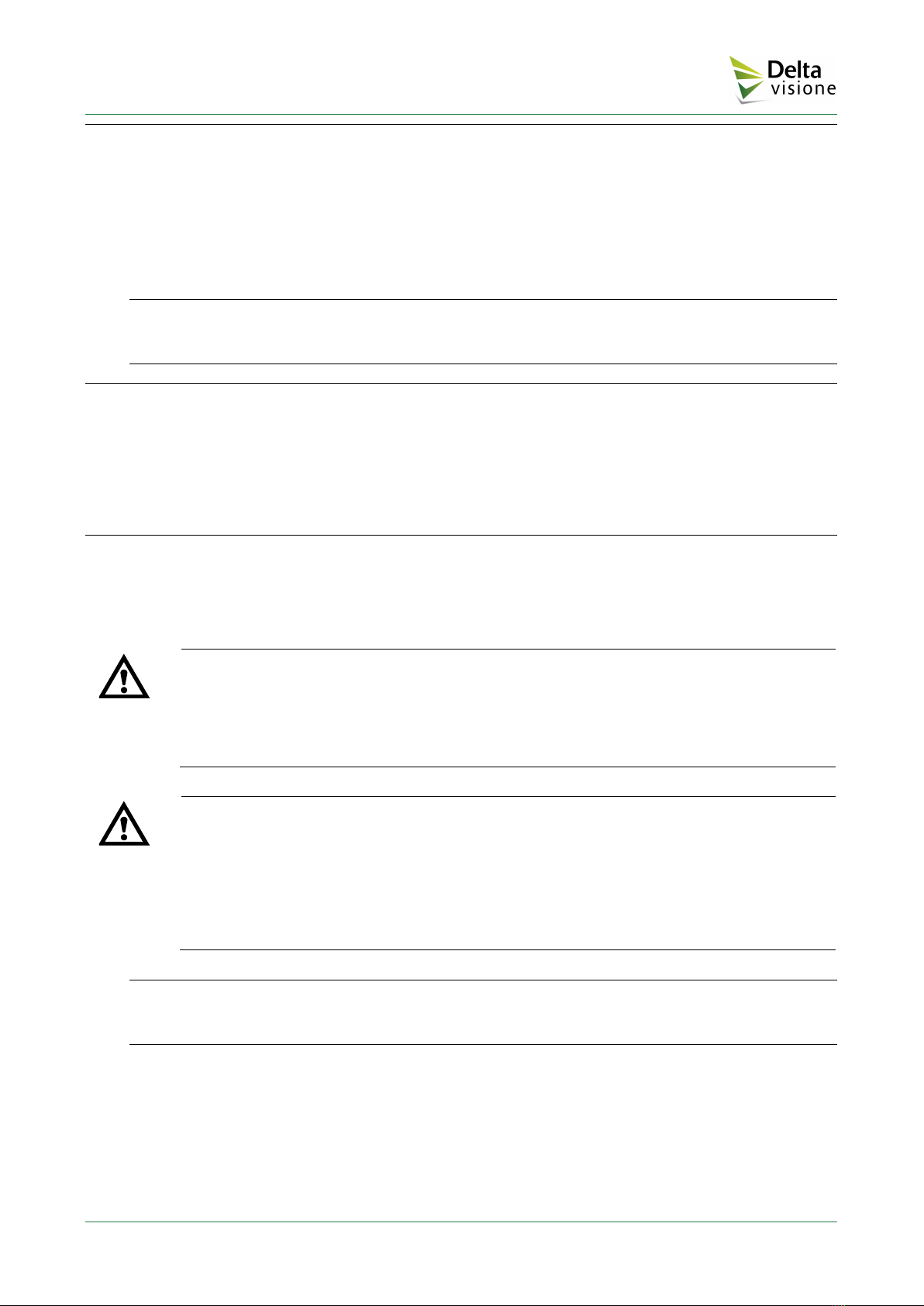
In order to obtain an efficient service intervention, follow this recommended procedure:

DEV7 –Use and Maintenance Manual
Pag. 9
•Go to the following address:
http://www.deltavisione.com
•Select CONTATTI (Contacts) in the top-right corner, then in “Scegli un tipo di richiesta” (select
a request type) select Richiesta assistenza (Service request)
Fill the form indicating the type of product involved using the data provided by the identification labels
applied on the Control Unit and/or on the Marking Head, detailing the reason of the request and/or the
error condition or malfunction.
Alternatively, send the service request to the following mail address:
support@deltavisione.com
providing the data detailed above.
Service requests can be issued through this phone number:
Tel. +39 0124 50 18 58
and will be satisfied accordingly to the availability of the service personnel.
For maintenance and service requests relative to electrical, mechanical and software issues, please refer
to the mail address provided above.
DEV7 –Use and Maintenance Manual
Pag. 10
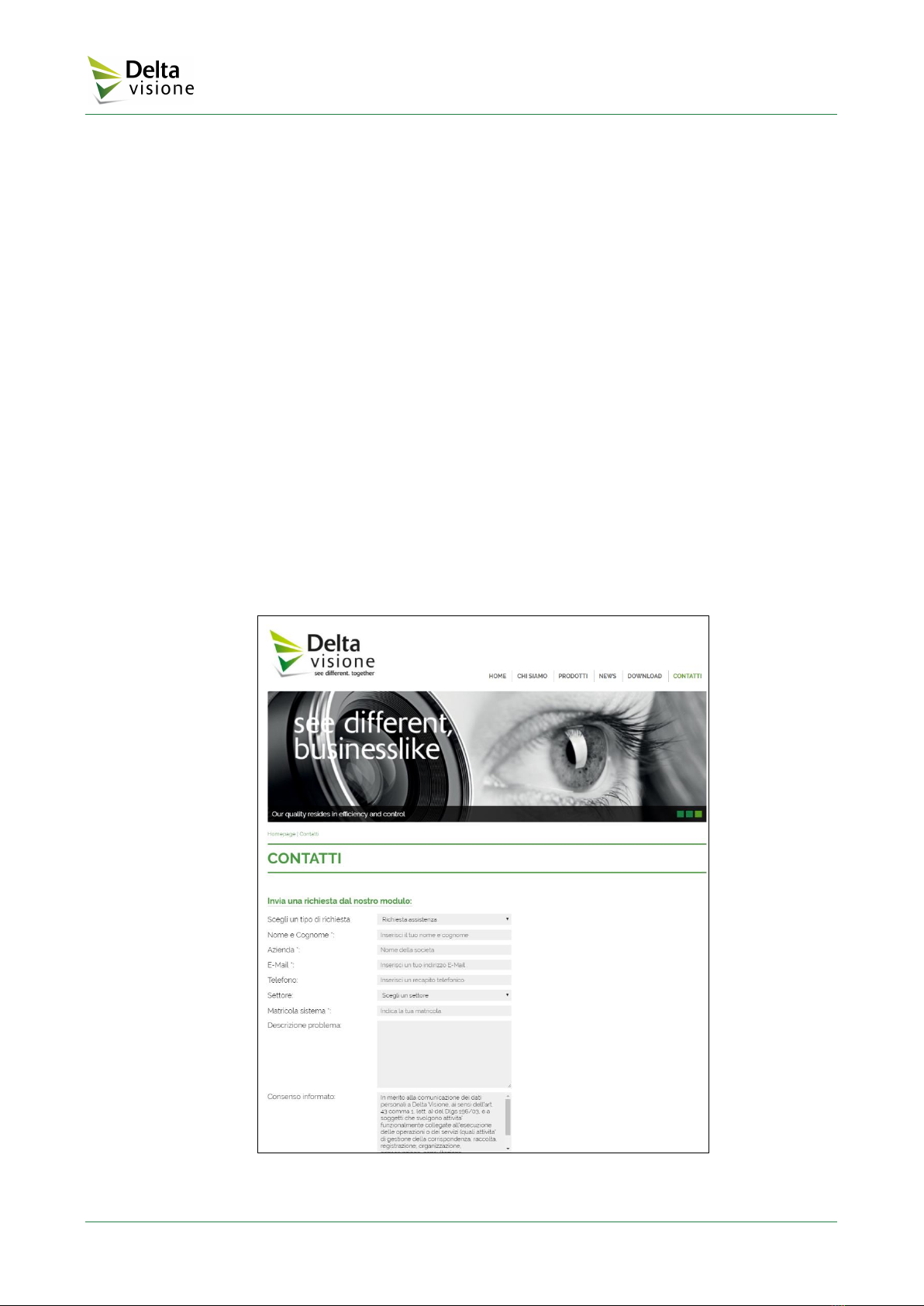
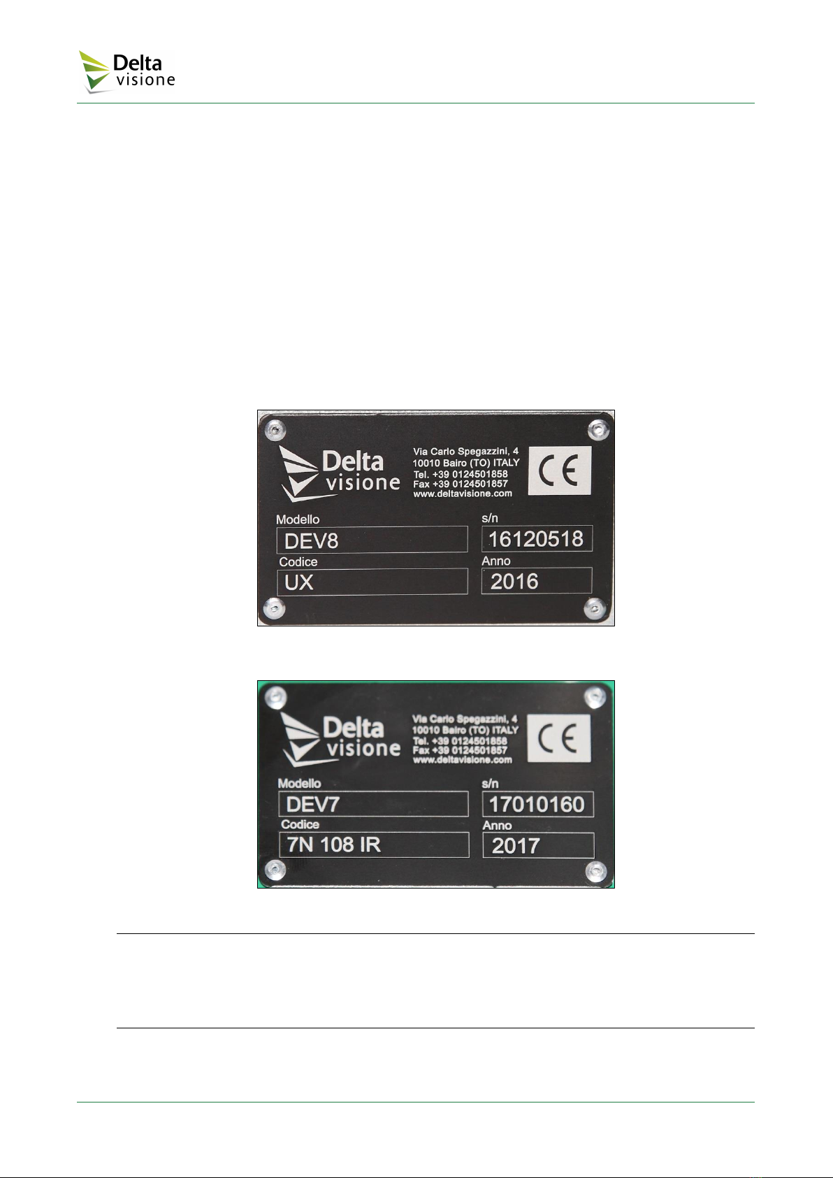
CE Labels
Both on the Control Unit and the Marking Head there is a CE label with the following identification
data:
•Model: DEV7
•Code: UX (Control Unit)
•Code: 7 XXX YY (Marking Head, see the note below)
•S/N: Serial number of the unit
•Year: 20xx
The identification data present on these labels must be provided at each service request or when ordering
spare parts.
The following figure shows an example of a CE label (for the Control Unit of a DEV8 model):
Figure 2 –CE Label of the Control Unit
Figure 3 –CE Label of the Marking Head
Note: The Marking Head code (e.g. 7 77 DV) is made up of an initial figure possibly followed by a
letter (7 for model DEV7, 7N for model DEV7N, 8 for model DEV8), two, three or four figures
indicating the size of the marking area (e.g. 77 indicates 70 x 70 mm marking area, 108 100 x 80 mm)
and two final figures identifying the punch type. Check Attachments 4 and 5 at the end of this document
for the details on the punch and marking unit types).
DEV7 –Use and Maintenance Manual
Pag. 11
2 Description and characteristics
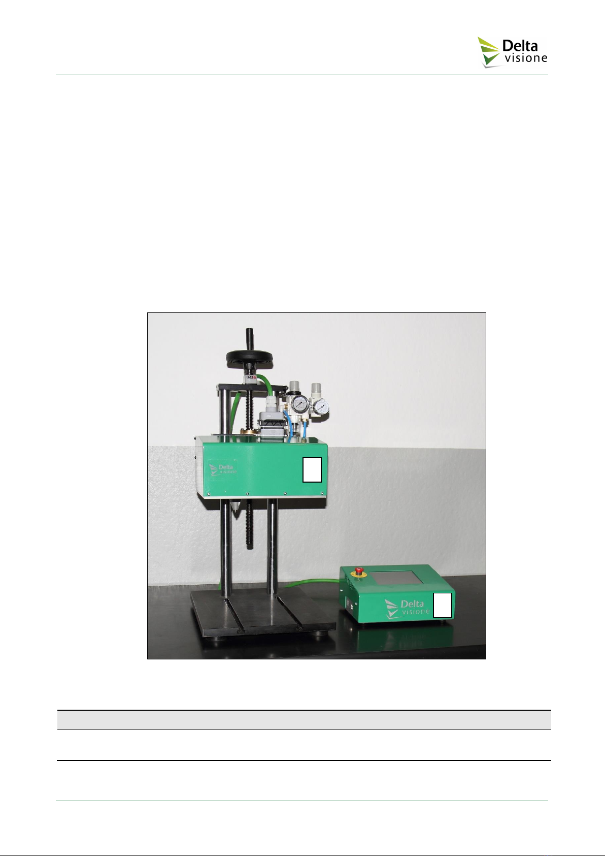
General description
The DEV7 scribe machine is made up of two main parts (see the figure below):
•Marking Head
•Hardware-software Control Unit.
Figure 4 –Overall view
Item
Description
1
Marking head
2
Hardware-software control unit
2
1
DEV7 –Use and Maintenance Manual
Pag. 12
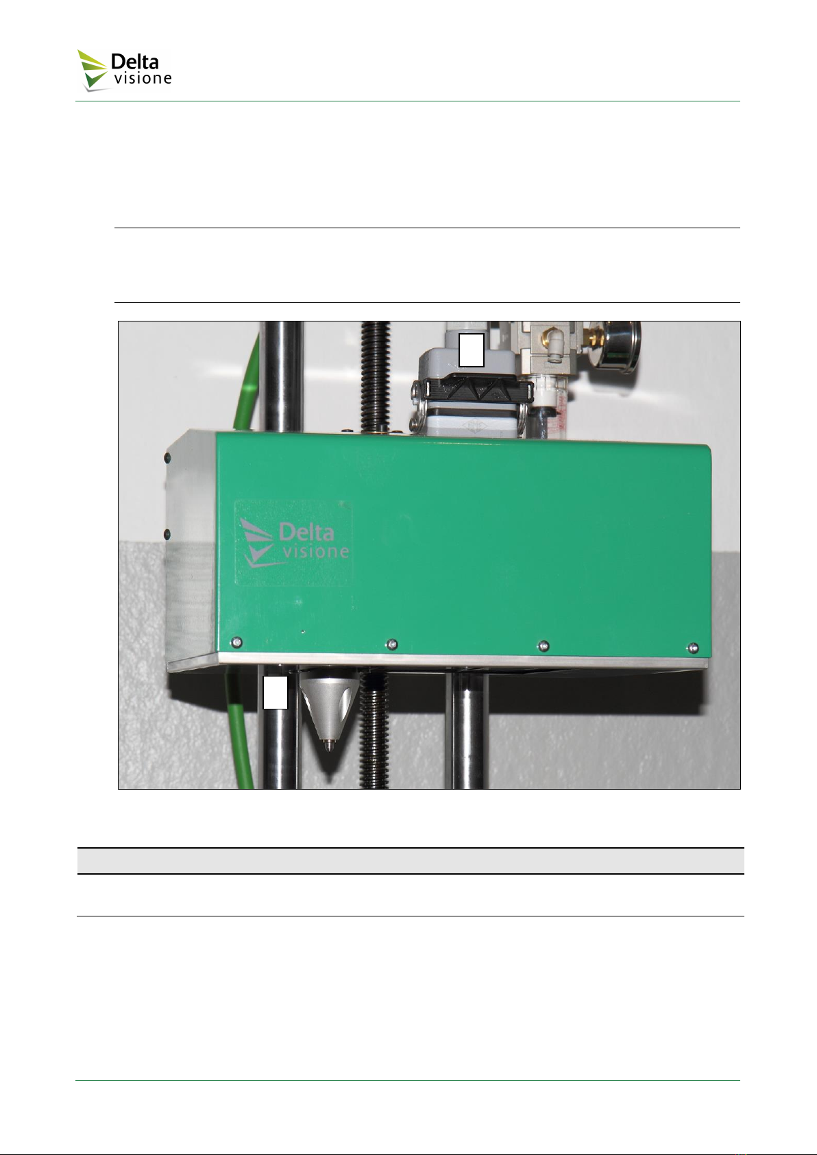
Marking head
The marking head contains the body of the punch that performs the marking operations, and the motors
and transmission elements for moving the punch. All the moving parts of the marking head are isolated
by a protective metal cover, which can be removed exclusively for maintenance purposes by unscrewing
the fastening screws and with the machine at a standstill.
ATTENTION! The protective cover guarantees safe use of the machine both for its intended use and
any other reasonably predictable uses, and for the risk of unintentionally incorrect movements by the
operator. Deliberate, voluntary access to the moving elements cannot however be ruled out and this
could represent a hazard that is not justified by any production needs.
Figure 5 –Marking head
Item
Description
1
Multipolar cable (from/to Hardware-software control unit) connector
2
Stylus unit
Various models are available, differentiated by the size of the marking head and therefore of the marking
area. A list of the currently available models and their dimensions and weights can be found in the
Appendix.
2
1
DEV7 –Use and Maintenance Manual
Pag. 13
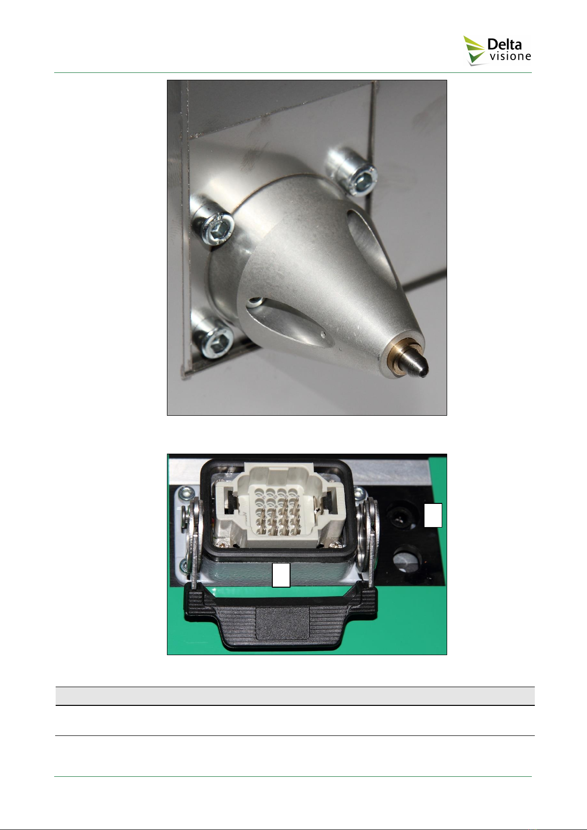
Figure 6 –Punch unit
Figure 7 –Multipolar cable and compressed air inlet
Item
Description
1
Multipolar cable (from/to Hardware-software control unit) connector
2
Compressed air inlet
2
1
DEV7 –Use and Maintenance Manual
Pag. 14
Control unit
The control unit of the DEV7 marking machine contains the hardware and software devices and power
electronics for controlling and driving the motors present in the marking head to which it is connected
by a multipolar cable in a protective sheath with a length of 2 m (standard version).
Figure 8 –Hardware-software Control Unit
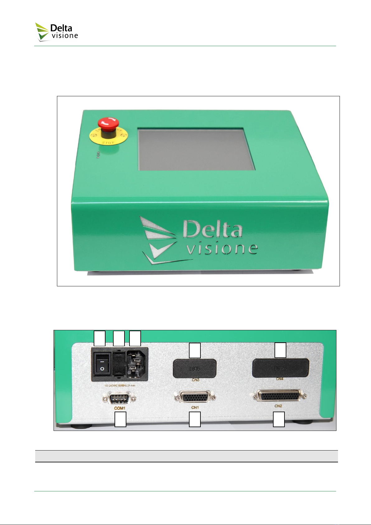
On the back side of the Control Unit there is the connectors’ compartment, also housing the power
supply socket and the power button.
Figure 9 –Back connectors and on/off switch
Item
Description
1
ON/OFF switch
2
Fuse holder 5X20 T5A
3
Mains cable connector
2
1
3
4
5
6
7
8

DEV7 –Use and Maintenance Manual
Pag. 15
Item
Description
4
Optional card connector
5
Optional card connector
6
COM1 RS232 serial port
(PLC or host with serial communication port controlling the marking cycle, for the details
refer to the System management software manual)
7
Marking head cable connector
8
Input/output cable connector
On the left side of the control unit there are other connectors (see the following figure).
Figure 10 –Connectors on the left side of the control unit
Item
Description
1
USB ports (2)
2
COM2 RS232 serial port (used by a Windows PC running the Mark Wizard software that
allows creating a marking file, see the details in the System management software manual)
The DEV7 marking machine uses a software interface that can be run directly from the integrated
keyboard or from an external keyboard connected to one of the USB ports situated on the side panel of
the Control Unit.
2
1

DEV7 –Use and Maintenance Manual
Pag. 16
E-Stop button
Figure 11 –Control Unit (top view)
The standard emergency stop button is situated in the upper left part of the control panel (see the figure
above).
The button can be pushed at any time, causing the immediate interruption of machine operation. If any
further operations are attempted, the following message will be displayed:
In addition to the above error message, the red LED on the left-hand side of the display will light up.
To exit from the emergency status and restore normal operation, simply press RET.

DEV7 –Use and Maintenance Manual
Pag. 17
Touch-screen
The touch-screen situated on the body of the control unit was designed to provide all the functions
necessary to perform the operations involved in controlling the marking machine (see example below).
Figure 12 –Touch-screen view
Note: At the end of the machine testing procedure, the display is covered with a film that is to be peeled
off slowly and carefully to avoid creating electrostatic charges.

Table of contents
Other Delta Visione Industrial Equipment manuals

Popular Industrial Equipment manuals by other brands


TopGears
TopGears ITG 125 Operation and maintenance manual

ABB
ABB HT842663 Operation manual

3M
3M 8350 D Instructions for the assembly

Schmalz
Schmalz FXP Operating instructions manual

Cooper Power Systems
Cooper Power Systems NOVA 15 Installation and operation instruction

Panasonic
Panasonic EXC14CH quick start guide


