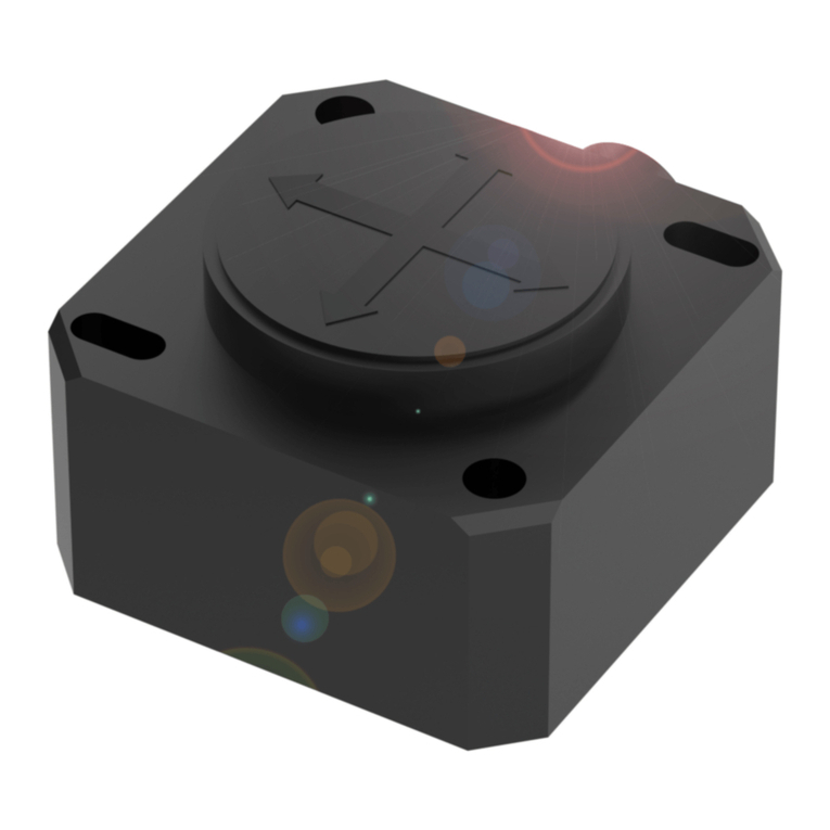
C.P. Electronics EBDHS-B01-DD User manual

Warning | Warnung | Advertencia |
Aviso | Attention | Attenzione | Waarschuwing
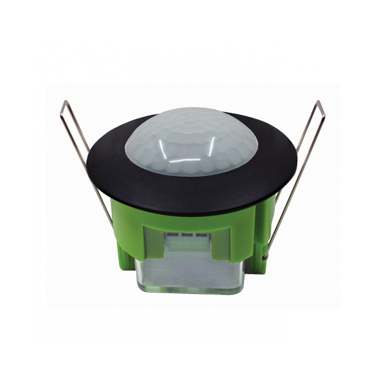
EBDHS-B01-DD
DALI digital dimming, high bay/high level, dedicated window for light sensor & IR communications,
presence PIR detector, specically for integration with an enclosure or a luminaire
Digitales DALI-Dimmen, Hochregal / Hochpegel, spezielles Fenster für Lichtsensor- und
IR-Kommunikation, Präsenz-PIR-Detektor, speziell für die Integration in ein Gehäuse oder eine Leuchte
Regulación digital DALI, bahía alta / nivel alto, ventana dedicada para sensor de luz y comunicaciones
IR, detector PIR de presencia, especícamente para integración con una carcasa o una luminaria
Dimerização digital DALI, alto nível / alto nível, janela dedicada para sensor de luz e comunicações IR,
detector PIR de presença, especicamente para integração com um gabinete ou luminária
Gradation numérique DALI, baie haute / haut niveau, fenêtre dédiée pour capteur de lumière et
communications IR, détecteur PIR de présence, spéciquement pour l’intégration avec un boîtier ou
un luminaire
Dimmer digitale DALI, high bay / high level, nestra dedicata per sensore di luce e comunicazioni IR,
rilevatore PIR di presenza, specico per l’integrazione con una custodia o un apparecchio di illuminazione
DALI digitaal dimmen, hoogbouw / hoog niveau, speciaal venster voor lichtsensor en IR-communicatie,
PIR-aanwezigheidsdetector, speciek voor integratie met een behuizing of een armatuur
EN This device should be
installed by a qualied electrician in
accordance with the latest edition
of the IEE wiring regulations.
The detector is specically
designed for integration with an
enclosure or a luminaire only
DE Dieses Gerät ist
ausschließlich von qualizierten
Elektrofachkräen zu installieren.
ES Sólo un electricista
cualicado debe instalar este
dispositivo.
PT Somente um eletricista
qualicado deve instalar este
dispositivo.
FR Seul un électricien
qualié peut installer ce dispositif.
IT Il dispositivo deve essere
installato da un elettricista
qualicato.
NL Dit apparaat moet
worden geïnstalleerd door een
gekwaliceerde elektricien.
WDA012 Issue 2 Installation Guide
EBDHS-B01-DD
High Bay Sensor (for Integration)
Downloads and Videos | Downloads und Videos | Descargas y Videos | Descargas e Videos |
Téléchargements & Vidéos | Downloads e Video | Downloads en Video’s
cpelectronics.co.uk/cp/A012

2
Dimensions (mm) | Abmessungen (mm) | Dimensiones (mm) | Dimensões (mm) | Dimensioni (mm) | Dimensies (mm)
Detection pattern | Erfassungsbereich | Patrón de detección | Padrão de detecção | Performance de détection |
Modello di rilevazione | Detectie zone
high sensitivity low
15m
32m
Height | Höhe | Altura |
Altura | La taille | Altezza
| Hoogte
Range Diameter | Bereich Durchmesser |
Diámetro de rango | Faixa de Diâmetro | Gamme
Diamètre | Gamma Diametro | Bereik diameter
15m 32m
10m 21m
6m 13m
Height | Höhe | Altura |
Altura | La taille | Altezza
| Hoogte
Range Diameter | Bereich Durchmesser |
Diámetro de rango | Faixa de Diâmetro | Gamme
Diamètre | Gamma Diametro | Bereik diameter
15m 20m
10m 13m
6m 8m
Walk towards | Annäherung | Aproximación frontal | Aproximaçao frontal | Marcher vers | Avvicinamento | Naar toe lopen
Walk across | Durchquerung | Aproximación lateral | Aproximaçao lateral | Marcher à travers | Attraversamento | Langs lopen
cpelectronics.co.uk/cp/wta
Walk towards & walk across explained | Erläuterung von Durchquerung und Annäherung | Explicación
de aproximación frontal / lateral | Explicaçao da Aproximaçao lateral e frontal | Marcher vers et à travers
expliqués | Spiegazione di avvicinamento e attraversamento | Verklaring van naar toe lopen en langs lopen
97
86 49 65
EN 64mm cut out
DE 64mm ausgeschnitten
ES Recorte de 64 mm
PT 64mm recortado
FR Découpe de 64 mm
IT Taglio da 64 mm
NL 64 mm uitgesneden

3
N
L
DIM –
DIM +
4
5
3
2
1
cpelectronics.co.uk/cp/841
WD841StandalonePresenceDetector manual | HandbuchzumStandalone-Präsenzmelder WD841 | Manualdeldetector
de presencia autónomo WD841 | Manual do Detector de Presença Autônomo WD841 | Manuel du détecteur de présence
autonomeWD841 | Manualedel rilevatoredi presenzastandalone WD841 | WD841Standalone Presence Detectorhandleiding
Dimming ouputs | Ausgänge dimmen | Salidas de atenuación | Saída de dimerização | Gradation des sorties |
Uscite di dimmerazione | Uitgangen dimmen
EN Basic insulation only. Although low voltage,
this is not an SELV output and should be treated as
if mains potential. Use mains rated wiring.
DE Nur Basisisolierung. Obwohl es sich um
eine niedrige Spannung handelt, handelt es
sich nicht um einen SELV-Ausgang und sollte als
Netzpotential behandelt werden. Verwenden
Sie Netzkabel.
ES Aislamiento básico solamente. Aunque es
de bajo voltaje, esta no es una salida SELV y debe
tratarse como si fuera un potencial de red. Utilice
el cableado nominal de red.
PT Isolamento básico apenas. Apesar de
baixa tensão, esta não é uma saída SELV e deve
ser tratada como potencial de rede. Use a fiação
nominal da rede.
FR Isolation de base seulement. Bien que
basse tension, il ne s’agit pas d’une sortie SELV et
doit être traité comme un potentiel de secteur.
Utilisez un câblage nominal.
IT Solo isolamento di base. Anche se a
bassa tensione, questa non è un’uscita SELV e
dovrebbe essere trattata come se il potenziale di
rete. Utilizzare il cablaggio nominale della rete.
NL Alleen basisisolatie. Hoewel dit een laag
voltage is, is dit geen SELV-uitgang en moet het
worden behandeld als netpotentiaal. Gebruik
hoofdstroombedrading.
Wiring | Verkabelung | Cableado | Ligações | Câblage | Cablaggio | Bedrading
EN Use the Dimming channel DIM+/- for
DALI dimmable load. Refer WD841 Standalone
Presence Detector manual for detailed V3
functionalities.
DE Verwenden Sie den Dimmkanal DIM
+/- für dimmbare DALI-Last. Ausführliche
Informationen zu V3-Funktionen nden Sie im
Handbuch zum Standalone-Präsenzmelder
WD841.
ES Utilice el canal de atenuación DIM +/-
para carga regulable DALI. Consulte el manual
del detector de presencia autónomo WD841
para conocer las funciones detalladas de V3.
PT Use o canal de dimerização DIM
+/- para carga dimerizável DALI. Consulte o
manual WD841 Standalone Presence Detector
para funcionalidades V3 detalhadas.
FR Utilisez le canal de variation DIM
+/- pour une charge dimmable DALI. Reportez-
vous au manuel du détecteur de présence
autonome WD841 pour les fonctionnalités V3
détaillées.
IT Utilizzare il canale Dimming DIM +/- per
il carico dimmerabile DALI. Fare riferimento al
manuale del rilevatore di presenza standalone
WD841 per le funzionalità V3 dettagliate.
NL Gebruik het dimkanaal DIM +/- voor
dimbare DALI-belasting. Raadpleeg de
WD841 standalone aanwezigheidsdetector
handleiding voor gedetailleerde V3-
functionaliteiten.
EN Key
1. Neutral
2. Live
3. 10A circuit protection required
4. Dimmable DALI load
5. DALI control lines DIM +/-
DE Zeichenerklärung
1. Neutral
2. Netzspannungsführend
3. 10A Kurzschlusssicherung
nötig
4. Dimmbare DALI-Last
5. DALI Steuerleitungen DIM +/-
ES Leyenda
1. Neutro
2. Fase
3. 10A protección de circuito
necesario
4. Carga DALI regulable
5. Líneas de control DALI DIM +/-
PT Legenda
1. Neutro
2. Fase
3. 10A proteção do circuito
necessário
4. Carga DALI regulável
5. Linhas de controle DALI DIM +/-
FR Légende
1. Neutre
2. Phase
3. 10A protection du circuit
nécessaire
4. Charge DALI dimmable
5. Lignes de contrôle DALI DIM +/-
IT Legenda
1. Neutro
2. Fase
3. 10A protezione del circuito
necessario
4. Carico dimmerabile DALI
5. Linee di controllo DALI DIM +/-
NL Legenda
1. Nul
2. Fase
3. 10A beveiliging nodig
4. Dimbare DALI-belasting
5. DALI-stuurleidingen DIM +/-
Wiring, DALI Dimmable load | Verkabelung, DALI Dimmbare Last | Cableado, carga regulable DALI | Fiação, carga regulável DALI |
Câblage, charge dimmable DALI | Cablaggio, carico dimmerabile DALI | Bedrading, DALI Dimbare belasting

4
Ø 64mm
1EN Cut a 64mm diameter
mounting hole.
DE Schneiden Sie ein
Befestigungsloch mit 64 mm
Durchmesser.
ES Corte un oricio de
montaje de 64 mm de diámetro.
PT Corte um orifício de
montagem de 64 mm de
diâmetro.
FR Découpez un trou
de montage de 64 mm de
diamètre.
IT Taglia un foro di
montaggio di 64 mm di diametro.
NL Snijd een montagegat
met een diameter van 64 mm.
EN This device is designed to be ush mount for integration with an
enclosure or a luminaire.
• Do not site the unit where direct sunlight & articial light might enter
the sensor.
• Do not site the sensor within 1m of any forced air heating or ventilation.
• Do not x the sensor to an unstable or vibrating surface.
• Occupancy is best detected when the ambient temperature is
dierent to that of the human body, thus, use within -20 to 35ºC
ambient temperature.
DE Dieses Gerät ist für die Unterputzmontage zur Integration in ein
Gehäuse oder eine Leuchte konzipiert.
• Einheit so anbringen, dass der Sensor vor direkter
Sonneneinstrahlung geschützt ist.
• Sensor mit Mindestabstand von 1m zu Lichtquellen, Luheizung
oder Ventilation anbringen.
• Sensor nicht an einer instabilen oder vibrierenden Oberäche
montieren.
• Bezetting wordt het best gedetecteerd wanneer de
omgevingstemperatuur anders is dan die van het menselijk lichaam,
dus gebruik binnen een omgevingstemperatuur van -20 tot 35 ° C.
ES Este dispositivo está diseñado para ser empotrado para su integración
con un gabinete o una luminaria.
• Evite que la luz del sol incida directamente sobre el sensor.
• No coloque el sensor a menos de 1m de fuentes de iluminación,
salidas de calefacción por aire forzado o ventilación.
• No je el sensor a supercies que vibren o no sean estables.
• La ocupación se detecta mejor cuando la temperatura ambiente es
diferente a la del cuerpo humano, por lo tanto, use dentro de -20 a
35ºC de temperatura ambiente.
PT Este dispositivo foi projetado para ser embutido para integração
com um gabinete ou luminária.
• Não instale a unidade num local onde a luz solar direta possa incidir
no sensor.
• Não coloque o sensor a menos de 1m de qualquer iluminação,
aquecimento ou ventilação de ar forçado.
• Não xe o sensor em uma superfície instável ou sujeito a vibrações.
• A ocupação é melhor detectada quando a temperatura ambiente é
diferente da do corpo humano, portanto, use entre -20 a 35ºC.
FR Cet appareil est conçu pour être encastré pour une intégration avec
un coret ou un luminaire.
• Ne pas placer l’unité dans une position où la lumière directe du soleil
pourrait pénétrer dans le capteur.
• Ne pas placer le capteur à moins d’unmètre de tout dispositif
d’éclairage, de chauage ou de ventilation à air forcé.
• Ne pas xer le capteur sur une surface instable ou vibrante.
• L’occupation est mieux détectée lorsque la température ambiante est
diérente de celle du corps humain, utilisez donc entre -20 et 35 ° C
de température ambiante.
IT Questo dispositivo è progettato per essere montato a lo per
l’integrazione con una custodia o un apparecchio di illuminazione.
• Non collocare l’unità in una posizione in cui la luce diretta del sole
possa entrare nel sensore.
• Non posizionare il sensore a meno di un metro da un qualsiasi tipo di
illuminazione, sistema di riscaldamento o ventilazione.
• Non installare il sensore su superci instabili o soggette a vibrazioni.
• L’occupazione viene rilevata meglio quando la temperatura ambiente
è diversa da quella del corpo umano, quindi utilizzare entro -20 a 35 °
C.
NL Dit apparaat is ontworpen om verzonken te worden gemonteerd
voor integratie in een behuizing of een armatuur.
• Plaats het apparaat niet op een locatie waar direct zonlicht de sensor
kan binnendringen.
• Plaats de sensor niet op minder dan 1 meter afstand van verlichting,
geforceerde luchtverwarming of ventilatie.
• Bevestig de sensor niet op een onstabiel of trillend oppervlak.
• Bezetting wordt het best gedetecteerd wanneer de
omgevingstemperatuur anders is dan die van het menselijk lichaam,
dus gebruik binnen een omgevingstemperatuur van -20 tot 35 ° C.
Installation | Instalación | instalação | Installazione | Installatie
35mm
6mm
2
Wire stripping | Abisolieren | Pelado de cables | Descascamento do o | Dénudage des câbles | Spelatura del lo | Kabelstrippen
EN Strip the wires as shown opposite. Presence
detector does not require earth conductor.
DE Abisolieren Sie die Kabel wie dargestellt. Der
Melder benötigt keinen Erdanschluß.
ES Pele los cables como se muestra en el
dibujo. El detector no requiere cable de tierra.
PT Descarne os cabos como mostrado ao
lado. Este detector não requer conductor de terra.
FR Dénudez les câbles comme indiqué
ci-contre. Le détecteur de présence ne nécessite
pas de conducteur de terre.
IT Spelare i li come mostrato. Il rilevatore di
presenza non richiede il cavo di terra.
NL Strip de aders zoals weergegeven op de
aeelding hiernaast. Aardingsdraad is niet vereist.
Create mounting hole | Montageloch erstellen | Crear agujero de montaje | Criar orifício de montagem | Créer un trou de
montage | Crea un foro di montaggio | Maak een montagegat

5
4
Clamp cable | Zugentlastung | Abrazadera para el cable | Fixação do cabo | Serrer les câbles | Morsetto per il cavo | Trekontlasting
3
Wire in plugs & connect to detector | Verdrahtugn & Anschluß des Melders | Cableado y conexión del sensor | Cablagem e ligação do
sensor | Câbler le bornier et connecter au détecteur | Cablaggio e connessione al rilevatore | Bedrading & aansluiten op detector
EN Wire in plug/s, using wiring diagram on page 3 as
a guide. Connect the plug/s to the detector.
DE Zum Anschluß des Melders verwenden Sie das
Schaltbild. Verwenden Sie dazu den /die beiliegenden
Stecker.
ES Cablear siguiendo el esquema de la página 3
como guía. Conectar las bornas al sensor.
PT Efectuar as ligações seguindo o esquema na
pág.3 como indicação. Ligar os bornes ao sensor.
FR Raccorder les câbles au bornier débrochable en
respectant le schéma de câblage page 3. Connecter le
bornier au détecteur.
IT Collegare il morsetto usando il cablaggio
indicato a pagina 3 come guida. Connetti il morsetto
al rilevatore.
NL Aders aansluiten in de aansluitklem(men),
gebruik het bedradingsschema op pagina 3 als richtlijn.
Steek de aansluitklem(men) in de detector.
EN The cable clamp usage is optional for
this product. If needed, customer
needs to order it separately.
Continue tightening the screws until the clamp bar
snaps out and is tightly engaged against the cable/s.
The cable clamp must clamp the outer sheath only.
DE Die Verwendung der Kabelklemme ist
für dieses Produkt optional. Bei Bedarf
muss der Kunde es separat bestellen.
Ziehen Sie die Schrauben weiterhin an, bis die Klemme
einrastet und fest am Kabel sitzt. Die Kabelklemme
darf nur die äußere Ummantellung einklemmen.
ES El uso de abrazadera de cable es opcional
para este producto. Si es necesario, el
cliente debe solicitarlo por separado.
Continuar apretando los tornillos hasta que la barra
abrazadera salga y se ajuste bien con el cable. La
abrazadera para cables solo debe sujetar la funda.
PT O uso de braçadeira de cabo é opcional
para este produto. Se necessário, o cliente
precisafazero pedidoseparadamente.
Apertar os parafusos até que a barra de xação se
encaixe totalmente e prenda bem o cabo. O grampo do
cabo deve xar apenas o revestimento externo.
FR L’utilisation du serre-câble est facultative
pour ce produit. Si nécessaire, le client
doit le commander séparément.
Continuez de serrer les vis jusqu’à ce que la barre de
xation sorte et se serre fortement sur le câble. Le serre-
câbles doit uniquement serrer la gaine extérieure.
IT L’utilizzo del morsetto del cavo è
opzionale per questo prodotto. Se
necessario, il cliente deve ordinarlo
separatamente.
Continuare a stringere le viti no a quando la barra del
morsetto non scatti e si ssi leggermente sul cavo.
Applica il morsetto alla sola guaina esterna del cavo.
NL Het gebruik van de kabelklem is
optioneel voor dit product. Indien nodig
dient de klant deze apart te bestellen.
Blijf de schroeven aandraaien totdat de beugel los
komt en de kabel stevig vastklemt. De beugel moet
alleen de buitenmantel vastklemmen.
EN Bend the springs up and push detector through
hole. When fully inserted the springs snap back to hold
the device in place.
To avoid injury, take care when bending springs.
DE Federn nach oben biegen und Detektor
durch die Önung. Sobald der Detektor vollständig
eingeschoben ist, schnappen die Federn zurück und
halten das Gerät fest an Ort und Stelle.
Achten Sie auf die Spannfedern um Verletzungen zu
vermeiden
ES Doble los muelles hacia arriba e introduzca el
detector. Cuando esté totalmente introducido, los
muelles saltan para mantener el dispositivo en su lugar.
Doble los muelles con cuidado al montar la unidad.
PT Dobre as molas para cima e empurre detector
através. Ao serem totalmente inseridas as molas
saltam de volta para manter o dispositivo no lugar.
Para evitar ferimentos, tenha cuidado quando
manipule as molas.
FR Replier les ressorts vers le haut et pousser
le détecteur à travers. Quand les ressorts sont
complètement insérés, ils se remettent dans leur
position initiale pour maintenir le dispositif en place.
Pour éviter toute blessure, faire attention lors de
la compression des ressorts.
IT Piegare le molle verso l’alto e inserire il rilevatore.
Una volta inserito, le molle si riassestano ssando il
dispositivo in posizione.
Per evitare infortuni, prestare attenzione quando
si piegano le molle.
NL Buig de veren omhoog en duw het apparaat
door. Wanneer de veren volledig door de sparing zijn
klappen deze terug om het apparaat op zijn plek te
houden.
Om letsel te voorkomen, wees voorzichtig met
het buigen van de veren.
Install detector | Melder installieren | Instalación del detector | Instalaçao do detector | Installer le détecteur |
Installazione del sensore | Installeer detector
5

6
Parameter Default Range / Option Description
Timeout 20 0 – 99 minutes How long the lights stay on for aer movement has stopped.
This sets both Timeout (channel 1) and Timeout (channel 2) to the same value.
Select 0 for a 10 second delay (use for commissioning only).
Sensitivity On 91 – 9 Sensitivity level for detecting further movement when the lights are already on.
1 = minimum, 9 = maximum (least movement required to trigger the lights).
Sensitivity O 91 – 9 Sensitivity level for detecting any movement when the lights are o.
1 = minimum, 9 = maximum (least movement required to trigger the lights).
Manual Timeout 10 0 – 99 minutes Sets the time period for the unit to hold its output state aer a manual override
command is performed with a handset.
This period is cancelled once motion detection Timeout period ends. If no
movement is ever detected, the Manual Override Cancel command can be
applied to cancel this operation so that the unit is ready to act immediately to
the next motion detection.
Walk Test LED O On / O When set to On a red LED on the sensor ashes when movement is detected.
Use this feature to check for adequate sensitivity levels.
Disable Detect No Yes / No Disables presence / absence detection, so that the detector can’t control
switching but can control dimming output. Use this mode when the unit is for
maintained illuminance only.
Power Up State Yes Yes / No Select No for a 40 second delay aer initial power up before the detector
starts detecting and changing outputs.
Select Yes for no delay - the detector will always power up detecting.
Inhibit (secs) 11 - 99 seconds The time to wait aer the detector turns lights o before it can retrigger them.
This inhibit function prevents inadvertent eects of vibrations caused by relay
contact switching movement on highly sensitive models such as microwave
technology sensors. Adjust only if signs of self re-triggering are happening.
Warning: High values would render undesirable delays in the sensor’s
response to movement.
UNLCDHS Programming – Detector Parameters
Basic Parameters for EBDHS-B01-DD
Programming Menu
EN Below is a list of parameters applicable to this product. Other
parameters found in the handset should NOT be used. If these are
inadvertently changed, please apply the “Factory Reset” function before
initiating the commissioning process.
DE Nachfolgend nden Sie eine Liste der Parameter, die für dieses
Produkt gelten. Andere Parameter des Mobilteils sollten NICHT verwendet
werden. Sollten diese versehentlich geändert werden, wenden Sie bitte
vor der Inbetriebnahme die Funktion „Factory Reset“ an.
ES A continuación se muestra una lista de parámetros aplicables a
este producto. NO se deben utilizar otros parámetros que se encuentran
en el teléfono. Si se modican inadvertidamente, aplique la función
“Factory Reset” antes de iniciar el proceso de puesta en marcha.
PT Abaixo está uma lista de parâmetros aplicáveis a este produto.
Outros parâmetros encontrados no aparelho NÃO devem ser usados. Se
eles forem alterados inadvertidamente, aplique a função “Reinicialização
de fábrica” antes de iniciar o processo de comissionamento.
FR Vous trouverez ci-dessous une liste des paramètres applicables
à ce produit. Les autres paramètres trouvés dans le combiné ne doivent
PAS être utilisés. Si ceux-ci sont modiés par inadvertance, veuillez
appliquer la fonction « Factory Reset » avant de lancer le processus de
mise en service.
IT Di seguito è riportato un elenco di parametri applicabili a questo
prodotto. Gli altri parametri presenti nel portatile NON devono essere
utilizzati. Se questi vengono modicati inavvertitamente, applicare la
funzione “Factory Reset” prima di avviare il processo di messa in servizio.
NL Hieronder vindt u een lijst met parameters die van toepassing zijn
op dit product. Andere parameters in de handset mogen NIET worden
gebruikt. Als deze per ongeluk worden gewijzigd, moet u de functie
“Fabrieksreset” toepassen voordat u het inbedrijfstellingsproces start.

7
Parameter Default Range / Option Description
Light Level (MI) 999 1 – 950
(999 = maintained
illuminance o)
Sets a target light level to be maintained by the lighting system.
Limit the target LUX setting to within 950 LUX which when mounted on the
ceiling would equate to around 1900LUX on desk level for a reectance factor
situation of 0.5.
LUX Learn Level 00 – 950 Use with the Readback function to get the LUX level the unit is currently
reading. Press Send to update the Light Level (MI) parameter with this value.
Auto Brightness
%
00 – 100 (0 = disabled) Instead of setting LUX ON and OFF as individual parameters, Auto brightness
sets these parameters as the assigned percentage of Light Level (MI)
parameter value. This is the % amount above the Light Level (MI) parameter
value being used to set as the LUX OFF value. LUX ON will always be set xed at
10% below the target Light Level (MI) parameter when this function is utilized.
LUX On Level 999 1 – 950,
999=disabled
Sets the light level below which will turn on the output in conjunction with
movement control. The output will turn on without movement should the
Disable Detect parameter be set to YES.
999 disables both LUX ON and LUX OFF functions.
The LUX O Level value must always be greater than the LUX On Level value.
LUX O Level 999 1 – 950,
999=disabled
Sets the light level above which will turn OFF the output in conjunction with
movement control.
999 disables both LUX ON and LUX OFF functions.
The LUX O Level value must always be greater than the LUX On Level value.
LUX On Time 00 – 99 minutes When the ambient light falls below LUX ON Level, the time to wait before
switching on the lights. If at any time during the timed delay the LUX change
reverses then the process is cancelled. Minimum time of around 15 seconds
is set for a value of 0.
If you try to turn lights on using a switch or handset, the lights will go on
regardless of ambient light level. However, if there is sucient ambient light,
they will turn o again aer LUX O Time.
LUX O Time 00 – 99 minutes When the ambient light rises above LUX OFF Level, the time to wait before
switching o the lights. If at any time during the timed delay the LUX change
reverses then the process is cancelled. Minimum time of around 15 seconds
is set for a value of 0.
UNLCDHS Programming – LUX Control
Basic Parameters for EBDHS-B01-DD
UNLCDHS Programming – Conguration
Basic Parameters for EBDHS-B01-DD
Parameter Default Range / Option Description
Factory Reset – – Clears any programmed settings and returns the device to its default set-up.
So Reset – – Reboots the device, but retains all current settings. Must leave value at zero.
IR Enabled Yes Yes / No Set to No to prevent the device from receiving commands from the handset.
The device’s LED will ash several times if you try to send a command when in
this state. Set to Yes to re enable programming.

8
Parameter Default Range / Option Description
On Value 99 0 – 99 Dimmed output level when lights manually switched on or via detection of
occupancy.
O Value 00 – 99 Dimmed output level when lights manually switched o or aer detector
times out.
Burn-in Hours 01 – 999 hours
(0 = disabled)
Determines how long the output will be at 100% so that new lamps burn-in.
The burn-in time is not aected by power supply interruptions.
Speed (On) 40 0 – 99 seconds Determines the dimming response speed during the set up time upon power
ON. Measured in 0.1 sec intervals.
If set to “0” will disable dimming for Set Seconds below, used if ttings are
required to warm up before dimming.
Speed (Setup) 50 – 99 Determines how long the dimming response set-up period lasts upon power-
up or on setting change. This enables a faster set up time.
Set Seconds 120 0 – 999 seconds Sets the dimming response speed aer the setup time has nished.
Measured in 0.1 sec intervals (i.e. a value of 40 means 4 seconds).
UNLCDHS Programming – Output Ch. 2
Advance Parameters available for EBDHS-B01-DD
UNLCDHS Programming – Device information
Under the device Info menu are items about the device that can be read back to the handset.
Note: Not all devices support any or all of the information below.
• Range: e.g Standalone
• Part number: e.g MWS6
• Variant: e.g DD, PRM output variants
• Version: Version of soware of the device.

9
UNLCDHS Programming – User
Basic Parameters for EBDHS-B01-DD
Parameter Default Range / Option Description
Select Scene 11 – 8 The preset dimming levels are as follows (does not operate the relay outputs):
Scene 1 – Maintained illuminance,
Scene 2 – 100%, Scene 3 – 75%, Scene 4 – 50%, Scene 5 – 25%,
Scene 6 – 15%, Scene 7 – 10%, Scene 8 – 0% (min)
Scene Up – – Changes the scene from 1 up to 8. (1–6 for pre V3 models)
Scene Down – – Changes the scene from 8 down to 1. (6 down to 1 for pre V3 models)
Set Scene Level 00 – 255 Changes a particular scene’s preset level. Select the scene rst using Select
Scene and then send Set Scene Level.
255 = 100%, 191 = 75%, 128 = 50%, 64 = 25%, 26 = 10%, 0 = 0% (min)
Raise – – Increases light level. Reverts to programmed light levels when absence
detected.
Lower – – Decreases light level. Reverts to programmed light levels when absence
detected.
Manual Override
On*
– – Turns lights on and reverts to automatic operation aer the period set by
Manual Timeout in the Detector Params menu.
Manual Override
O*
– – Turns lights o and reverts to automatic operation aer the period set by
Manual Timeout in the Detector Params menu.
Manual Override
Cancel*
– – Cancels the manual on and o overrides, returning the detector to normal
operation.
* Operations
EN The unit will not signify its status when overridden by the handset.
It will return to its automatic motion detection after the manual timeout
period. Alternatively, it can return immediately to motion detection by
use of the ‘Manual Override Cancel’ or a ‘Soft Reset’ command via the
handset.
DE Das Gerät zeigt seinen Status nicht an, wenn es vom Mobilteil
überschrieben wird. Nach der manuellen Zeitüberschreitung kehrt es
zur automatischen Bewegungserkennung zurück. Alternativ kann es mit
dem Befehl „Manual Override Cancel“ oder einem „Soft Reset“-Befehl
über das Mobilteil sofort zur Bewegungserkennung zurückkehren.
ES La unidad no indicará su estado cuando sea anulada por el
teléfono. Volverá a su detección automática de movimiento después del
período de tiempo de espera manual. Alternativamente, puede regresar
inmediatamente a la detección de movimiento mediante el uso de la
‘Cancelación de anulación manual’ o un comando de ‘Reinicio suave’ a
través del teléfono.
PT A unidade não indicará seu status quando substituída pelo
monofone. Ele retornará à detecção automática de movimento após o
período de tempo limite manual. Alternativamente, ele pode retornar
imediatamente à detecção de movimento usando o ‘Cancelamento de
substituição manual’ ou um comando de ‘Reinicialização suave’ através
do fone.
FR L’unité n’indiquera pas son état lorsqu’elle est ignorée par le
combiné. Il reviendra à sa détection automatique de mouvement après
la période de temporisation manuelle. Alternativement, il peut revenir
immédiatement à la détection de mouvement à l’aide de la commande «
Annulation manuelle de la priorité » ou d’une « Réinitialisation logicielle
» via le combiné.
IT L’unità non indicherà il suo stato quando viene ignorata dal
ricevitore. Tornerà al rilevamento automatico del movimento dopo il
periodo di timeout manuale. In alternativa, può tornare immediatamente
al rilevamento del movimento utilizzando il comando “Manual Override
Cancel” o un comando “Soft Reset” tramite il telecomando.
NL Het apparaat geeft zijn status niet aan wanneer het wordt
genegeerd door de handset. Het keert terug naar de automatische
bewegingsdetectie na de handmatige time-outperiode. Als alternatief
kan het onmiddellijk terugkeren naar bewegingsdetectie door gebruik te
maken van de ‘Manual Override Cancel’ of een ‘Soft Reset’-commando
via de handset.

10
Presence Detection
1
2
3
Testing | Prüfen | Pruebas | Teste | Test | Veriche | Testen | Тестирование
EN 1. Power up the sensor. The load should
come on immediately.
2. Vacate the room or remain very still and wait
for the load to switch o (this should take less
than 20 minutes).
3. Enter the room or make some movement and
check that the load switches on.
DE 1. Schließen Sie den Sensor an die
Stromversorgung an - das System sollte sich
sofort einschalten.
2. Verlassen Sie den Raum oder stehen Sie
ganz still, um zu prüfen, ob das System sich
ausschaltet (Dies erfolgt nach ca. 20Minuten
nach der letzten Erfassung).
3. Betreten Sie den Raum oder bewegen Sie
sich, um sicherzustellen, dass das System sich
einschaltet.
ES 1. Encienda el sensor: la carga debería
encenderse inmediatamente.
2. Salga de la habitación o permanezca muy
quieto y espere a que la carga se apague
(deberían requerirse menos de 20 min).
3. Entre en la habitación o realice algún
movimiento y compruebe que la carga se enciende.
PT 1. Ligue o sensor - a carga deve ser ativada
imediatamente.
2. Desocupe a sala ou permaneça imóvel e
aguarde até a carga ser desativada
(isto deve levar menos de 20 minutos).
3. Entre na sala ou faça algum movimento e
verique se a carga é ativada.
FR 1. Alimenter le capteur: la charge devrait
s’allumer immédiatement.
2. Quitter la pièce ou rester immobile et attendre
que la charge s’éteigne (ceci devrait prendre
moins de 20 minutes).
3. Entrer dans la pièce ou bouger et vérier que
la charge s’allume.
IT 1. Accendi il sensore: il carico dovrebbe
attivarsi immediatamente.
2. Abbandona la stanza o cerca di restare il più
fermo possibile e attendi lo spegnimento del carico
(dovrebbe richiedere meno di 20 minuti).
3. Entra nella stanza o esegui qualche movimento
per vericare che il carico si attivi.
NL 1. Zet spanning op de sensor. De ballast
moet onmiddellijk inschakelen.
2. Verlaat de ruimte of zorg dat er geen beweging
is binnen de detectiezone en wacht tot de ballast
uitschakelt (dit duurt 20 minuten).
3. Ga de ruimte in of maak bewegingen binnen
de detectiezone en controleer of de ballast wordt
ingeschakeld.
Default Settings | Werkseinstellung | Parámetros por defecto | Congurações por omissão |
Paramètres par défaut | Impostazioni predenite | Standaard instellingen | Настройки по умолчанию
EN Time out: 20 minutes.
LUX on level: 999
LUX o level: 999
Sensitivity on: 9
Sensitivity o: 9
Adjustments can be made using the optional
UHS5 or UNLCDHS handsets.
DE Nachlaufzeit: 20 Minuten
LUX Einschaltschwelle: 999
Lux Ausschaltschwelle: 999
Empndlichkeit ein: 9
Empndlichkeit aus: 9
Einstellungsänderungen können mit den
Ferbedienungen UHS 5 oder UNLCD HS
vorgenommen werden.
ES Tiempo retardo hasta apagado: 20
minutos
Nivel Lux Encendido: 999
Nivel Lux Apagado: 999
Sensibilidad en: 9
Sensibilidad desactivada: 9
Los ajustes se pueden hacer usando los
mandos UHS5 y UNLCDHS
PT Tempo limite: 20 minutos.
LUX on nível: 999
LUX o : 999
Sensibilidade ligada: 9
Sensibilidade desligada: 9
Os ajustes podem ser efectuados usando os
telecomandos opcionais UHS5 ou UNLCDHS.
FR Temporisation: 20 minutes
Seuil de luminosité pour
activation PIR: 999
Seuil de luminosité pour
désactivation PIR: 999
Sensibilité sur: 9
Sensibilité désactivée: 9
Toutes modications peuvent être faites en
utilisant les outils de conguration UHS5 ou
UNLCDHS.
IT Time out: 20 minuti.
Livello accensione LUX: 999
Livello spegnimento LUX: 999
Sensibilità attiva: 9
Sensibilità disattivata: 9
Le regolazioni possono anche essere eettuate
utilizzando l’opzionale telecomando UHS5 o
UNLCDHS.
NL Uitschakeltijd: 20 minuten
Lichtdrempel aan niveau: 999
Lichtdrempel uit niveau: 999
Gevoeligheid aan: 9
Gevoeligheid uit: 9
Aanpassingen kunnen worden uitgevoerd met
de optionele UHS5- of UNLCDHS-handset.

11
Eingehaltene
normen
IP-schutzklasse
Isolationsklasse
Material (gehäuse)
Feuchtigkeit
Betriebstemperatur
Bemessungss-
toßspannung
Zeitüberschreit-
ungsbereich
Max DALI Dim Load
Lichterkennungs-
bereich
Leiterkapazität
Sicherung
Versorgungsfrequenz
Energieverbrauch
Versorgungsspan-
nung AC
Gewicht
Teile-code
DE Technische Daten
EMC-2014/30/EU,
LVD-2014/35/EU
40
2
Flammenhemmendes
ABSundPC/ABS
5 bis 95 %
Luftfeuchtigkeit,
nichtkondensierend
-20 bis +35°C
2500V
10s-99m
Bis zu 10 Fahrers
Verwendbar
15-950 Lux
2.5mm²
= <10A MCB Typ B.
50Hz
Typisch 1,5 VA
230 VAC +/- 10%
0.2kg
EBDHS-B01-DD
Conformidad con
normativas
Grado de
protección IP
Clase de aislamiento
Material (carcasa)
Humedad
Temperatura de
funcionamiento
Voltaje nominal de
impulso
Rango de tiempo
fuera
Max DALI carga tenue
Rango de detección
de luz
Capacidad del
terminal
Protección del
circuito
Frecuencia de
suministro
El consumo de
energía
Voltaje de entrada
de CA
Peso
Código de pieza
ES Datos Técnicos
EMC-2014/30/EU,
LVD-2014/35/EU
40
2
ABS retardante a
llama y PC/ABS
5 a 95 % sin
condensación
-20 a +35°C
2500V
10s-99m
Hasta 10
conductores
15-950 Lux
utilizables
2.5mm²
<=10A MCB Tipo B
50Hz
1,5 VA típico
230 VAC +/- 10%
0.2kg
EBDHS-B01-DD
Compliance
IP rating
Insulation class
Material (casing)
Humidity
Operational
temperature
Rated impulse
voltage
Time out range
Max DALI dim load
Light detection
range
Terminal capacity
Circuit Protection
Supply frequency
Power Consumption
Supply voltage AC
Weight
Part code
EMC-2014/30/EU,
LVD-2014/35/EU
40
Class 2
Flame retardant
ABS and PC/ABS
5 to 95% non-
condensing
-20 to +35°C
2500V
10s-99m
Up to 10 drivers
Usable 15-950
Lux
2.5mm²
<=10A MCB Type B
50Hz
Typical 1.5VA
230 VAC +/- 10%
0.2kg
EBDHS-B01-DD
EN Technical Data FR Données Techniques
Conformité
Indice IP
Classe d’isolation
Matériau (boîtier)
Humidité
Température de
fonctionnement
Tension nominale
de tenue aux chocs
Plage de temps
mort
Charge dim DALI
max
Plage de détection de
lumière
Capacité des
terminaux
Protection des
circuits
Fréquence
d’alimentation
Consommation
d’énergie
Tension
d’alimentation CA
Poids
Code de la pièce
EMC-2014/30/EU,
LVD-2014/35/EU
40
2
Agent Ignifuge
ABS et PC/ABS
5 à 95 % non-
condensable
-20 à +35°C
2500V
10s-99m
Jusqu’à 10
conducteurs
Utilisable 15-950
Lux
2.5mm²
<=10A MCB Type B
50Hz
Typique 1,5VA
230 VAC +/- 10%
0.2kg
EBDHS-B01-DD
PT Dados Técnicos
Compatibilidade
Classicação IP
Classe de isola-
mento
Material (caixa)
Umidade
Temperatura
operacional
Tensão de impulso
nominal
Intervalo de tempo
limite
Carga fraca DALI
máxima
Faixa de detecção
de luz
Capacidade do
terminal
Proteção de circuito
Freqüência de
fornecimento
Consumo de
energia
Tensão de
alimentação CA
Peso
Código da peça
EMC-2014/30/EU,
LVD-2014/35/EU
40
2
ABS retardador de
chama e PC/ABS
5 a 95% sem
condensação
-20 a +35°C
2500V
10s-99m
Até 10 condutores
Utilizável 15-950
Lux
2.5mm²
<=10A MCB Tipo B
50Hz
1.5VA típico
230 VAC +/- 10%
0.2kg
EBDHS-B01-DD

WDA012 Issue 2 Installation Guide EBDHS-B01-DD
20663
CP Electronics
Brent Crescent, London NW10 7XR
t. +44 (0)333 900 0671
enquir[email protected]
www.cpelectronics.co.uk connect with us
Due to our policy of continual product improvement CP Electronics reserves the right to alter the specication of this product without prior notice.
Part Number | Artikelnummer |
Referencia | Referéncia | Référence
| Codice | Artikelnummer
Description | Beschreibung | Descripción | Descripção | Description | Descrizione | Omschrijving
EBDHS-DBB-WBRKT
Wall mount bracket for EBDHS range | Wandhalterung für EBDHS-Serie | Soporte de montaje en pared para la gama EBDHS |
Suporte de parede para a gama EBDHS | Support de montage mural pour la gamme EBDHS | Staa per montaggio a parete per gamma
EBDHS | Muurbeugel voor EBDHS-bereik
EBD-ENCIP1
Pre-drilled 64mm hole IP enclosure | Vorgebohrtes 64-mm-Loch-IP-Gehäuse | Carcasa IP pretaladrada de 64 mm de oricio |
Gabinete IP com furo pré-perfurado de 64 mm | Boîtier IP pré-percé de 64 mm | Custodia IP preforata con foro da 64 mm |
IP-behuizing met voorgeboorde gaten van 64 mm
EXD-HSC Extended wiring housing | Erweiterter Verdrahtungsraum | Ampliación de alojamiento de cables | Extensor adicional para cabos |
Enveloppe allongée pour câblage | Estensore per i cavi | Verlengde behuizing voor bedrading
DBB Surface mounting box | Deckenauaudose | Caja para montaje en supercie | Caixa para supercie | Accessoire pour montage
en saillie | Scatola a supercie | Opbouwdoos
EBDHS-MS Masking shields | Abschirmungen | Protectores | Máscaras delimitadoras de deteçao | Ecrans de masquage | Schermi di
mascheramento | Maskeerafscherming
EBDHS-MC Mains Cable Clamp cover | Abdeckung der Netzkabelklemme | Cubierta de la abrazadera del cable de red | Tampa do grampo do
cabo principal | Couvercle du serre-câble secteur | Copertura del morsetto del cavo di rete | Afdekking netkabelklem
UHS5
Compact, programming/commissioning handset | Kompakte Fernbedienung und Einstellhilfe | Mando para programación y
puesta en marcha | Controle remoto para ajustes/commisionamento | Combiné compact de programmation / mise en service |
Telecomando per programmazione/messa in servizio | Compacte conguratie handset
UNLCDHS
Universal LCD IR handset/commissioning handset | Fernbedienung und Einstellwerkzeug | Mando profesional con pantalla LCD
para programación y puesta en marcha | Controle remoto LCD Universal | Outil universel de conguration / mise en service avec
écran LCD | Telecomando Universale LCD | Gevanceerde handset
Accessories & associated products | Zubehör | Accesorios y productos asociados | Acessórios e productos associados |
Accessoires et produits associés | Accessori e prodotti associati | Toebehoren
IT Speciche Tecnichev
Conformità
Classicazione IP
Classe di isola-
mento
Materiale (rivesti-
mento)
Umidità
Temperatura
operativa
Tensione nominale
a impulso
Intervallo di tempo
Carico dim max DALI
Gamma di rileva-
mento della luce
Capacità del
morsetto
Protezione del
circuito
Frequenza di
alimentazione
Consumo di energia
Tensione di
alimentazione CA
Peso
Codice parte
EMC-2014/30/EU,
LVD-2014/35/EU
40
2
ABS ignifugo e
PC/ABS
Dal 5 al 95% senza
condensa
-20 al +35°C
2500V
10s-99m
Fino a 10 drivers
Utilizzabile
15-950 Lux
2.5mm²
<=10A MCB tipo B
50Hz
Tipico 1.5VA
230 VAC +/- 10%
0.2kg
EBDHS-B01-DD
Conformiteit
IP classicatie
Isolatieklasse
Materiaal
(behuizing)
Luchtvochtigheid
Operationele
temperatuur
Nominaal im-
pulsspanning
Time-outbereik
Max. DALI-
dimbelasting
Lichtdetectiebereik
Eindcapaciteit
Circuitbeveiliging
Voedingsfrequentie
Energieverbruik
Voedingsspanning
AC
Gewicht
Onderdeelcode
NL Technische data
EMC-2014/30/EU,
LVD-2014/35/EU
40
2
Vlamvertragend
ABS en PC/ABS
5 tot 95%, niet
condenserend
-20 tot +35°C
2500V
10s-99m
Tot 10
bestuurders
Bruikbaar 15-950
Lux
2.5mm²
<=10A MCB Type B
50Hz
Typisch 1,5 VA
230 VAC +/- 10%
0.2kg
EBDHS-B01-DD
Table of contents
Other C.P. Electronics Accessories manuals
C.P. Electronics
C.P. Electronics MWS1A-PRM User manual
C.P. Electronics
C.P. Electronics EBDSPIR-PRM User manual
C.P. Electronics
C.P. Electronics EBDHS-MB-DNET1 User manual
C.P. Electronics
C.P. Electronics SPIR-F User manual
C.P. Electronics
C.P. Electronics MWS3A-KNX User manual

C.P. Electronics
C.P. Electronics SPIR-FVF User manual
C.P. Electronics
C.P. Electronics ALC-PRM-VFC User manual
C.P. Electronics
C.P. Electronics EBMINT User manual
C.P. Electronics
C.P. Electronics MWS5 User manual
C.P. Electronics
C.P. Electronics SPIR-F/C-IP User manual

