BFT BOTTICELLI VENERE User manual

ISTRUZIONI D’USO E DI INSTALLAZIONE
INSTALLATION AND USER’S MANUAL
INSTRUCTIONS D’UTILISATION ET D’INSTALLATION
INSTALLATIONS-UND GEBRAUCHSANLEITUNG
INSTRUCCIONES DE USO Y DE INSTALACION
GEBRUIKS- EN INSTALLATIEAANWIJZINGEN
BOTTICELLIVENERE
BOTTICELLI VENERE
D811492 00100_01 22-04-09
AUTOMAZIONI PER PORTE BASCULANTI E SEZIONALI
AUTOMATION FOR OVERHEAD AND SECTIONAL GARAGE DOORS
AUTOMATION POUR PORTES BASCULANTES ET SECTIONALES
GARAGENTORANTRIEB FÜR SCHWING UND SEKTIONALTORE
AUTOMATIZACIONES PARA PUERTAS BASCULANTE Y SECCIONALES
AUTOMATISERINGEN VOOR KANTEL- EN SECTIEDEUREN
Attenzione! Leggere attentamente le “Avvertenze” all’interno! Caution! Read “Warnings” inside carefully! Attention! Veuillez lire attentivement les Avertissements qui se trouvent à l’intérieur!
Achtung! Bitte lesen Sie aufmerksam die„Hinweise“ im Inneren! ¡Atención¡ Leer atentamente las“Advertencias”en el interior! Let op! Lees de“Waarschuwingen”aan de binnenkant zorgvuldig!

2 - BOTTICELLI VENERE
D811492 00100_01

MANUALE D’USO ITALIANO
Nel ringraziarVi per la preferenza accordata a questo prodotto, la ditta è certa
che da esso otterrete le prestazioni necessarie al Vostro uso.Leggete attenta-
mente l’opuscolo “Avvertenze” ed il “Libretto istruzioni” che accompagnano
questo prodotto in quanto forniscono importanti indicazioni riguardanti la
sicurezza, l’installazione, l’uso e la manutenzione. Questo prodotto risponde
alle norme riconosciute della tecnica e della disposizioni relative alla sicurezza.
Confermiamo che è conforme alle seguenti direttive europee:89/336/CEE, 73/23/
CEE, 98/37/CEE, 99/05/CEE (e loro modifiche successive).
1) GENERALITÀ
Esso è adatto a motorizzare porte sezionali, porte basculanti debordanti a
molle a totale rientranza e porte basculanti a contrappesi mediante un ap-
posito braccio di traino. L’altezza massima della porta basculante non deve
superare i 3 metri. L’installazione di facile esecuzione, permette un rapido
montaggio senza alcuna modifica alla porta.Il blocco in chiusura è mantenuto
dal motoriduttore irreversibile.
Questo prodotto è stato progettato per motorizzare i sopra indicati tipi di
porte. Ogni altro impiego, sarà considerato contrario all’utilizzo previsto
dal fabbricante che, pertanto, non potrà risultare responsabile dei danni
a persone, animali o cose che eventualmente ne derivino.
2) SICUREZZA
L’automazione,se installata ed utilizzatacorrettamente,soddisfailgrado disicu-
rezzarichiesto.Tuttaviaè opportunoosservarealcuneregoledi comportamento
per evitare inconvenienti accidentali. Prima di usare l’automazione, leggere
attentamente le istruzioni d’uso e conservarle per consultazioni future.
• Tenere bambini, persone e cose fuori dal raggio d’azione dell’automazione,
in particolare durante il funzionamento.
• Non lasciare radiocomandi o altri dispositivi di comando alla portata dei
bambini onde evitare azionamenti involontari dell’automazione.
• Non contrastare volontariamente il movimento dell’anta.
• Non tentare di aprire manualmente la porta se non è stato sbloccato il si-
stema di blocco interno tirando con l’apposita cordina collegata al carrello
(fig.1), oppure attivato lo sblocco esterno (SM1 o SET/S fig. 2-fig.3).
• Non modicare i componenti dell’automazione.
• In caso di malfunzionamento, togliere l’alimentazione, attivare lo sblocco di
emergenza per consentire l’accesso e richiedere l’intervento di un tecnico
qualificato (installatore).
• Per ogni operazione di pulizia esterna, togliere l’alimentazione di rete.
• Tenere pulite le ottiche delle fotocellule ed i dispositivi di segnalazione lumi-
nosa.Controllare che rami ed arbusti non disturbino i dispositivi di sicurezza
(fotocellule).
• Per qualsiasi intervento diretto all’automazione, avvalersi di personale
qualificato (installatore) o centro assistenza tecnica.
• Annualmente far controllare l’automazione da personale qualicato.
• Controllare spesso l’impianto, ed in particolare cavi, molle e supporti per
scoprire eventuali sbilanciamenti, segni di usura o danni. Non usare l’auto-
mazionenelcasorisultasseronecessarieunariparazioneounaregolazione,
dal momento che un guasto all’installazione o una porta non correttamente
bilanciata potrebbero provocare ferite.
• Vericare mensilmente che il motore effettui l’inversione con un ostacolo
alto 50 mm dal suolo. Se il funzionamento non risultasse corretto, richiedere
l’intervento di un tecnico qualificato, dal momento che una regolazione non
corretta potrebbe costituire un pericolo.
3) MANOVRA DI EMERGENZA
Nel caso manchi l’energia elettrica o, di avaria del sistema, per eseguire la
manovra manualmente, bisogna tirare il cordino collegato al carrello come in
fig.1. Per autorimesse prive di uscita secondaria è obbligatorio montare un
dispositivo di sblocco dall’esterno con chiave tipo il Mod. SM1 (fig.2) o il Mod.
SET/S (g.3). ATTENZIONE: se la porta non è correttamente bilanciata, l’at-
tivazione del rilascio manuale potrebbe provocare un movimento incontrollato
della stessa.
4) SOSTITUZIONE DELLA LAMPADINA
La sostituzione della lampadina luce di cortesia si effettua togliendo la coper-
tura trasparente (Fig.4).
ATTENZIONE: Utilizzare esclusivamente lampade tipo 24V 25W max E14.
E14 24V
25W max
BOTTICELLI VENERE - 3
D811492 00100_01

USER’S MANUAL
ENGLISH
Thank you for buying this product, our company is sure that you will be more
than satisfied with the product’s performance. The product is supplied with
a “Warning” leaflet and an “ Instruction booklet ”. These should both be
read carefully as they provide important information about safety, installa-
tion, operation and maintenance. This product complies with the recognised
technical standards and safety regulations. We declare that this product is in
conformity with the following European Directives: 89/336/EEC, 73/23/EEC,
98/37/EEC, 99/05/EEC (and subsequent amendments).
1)GENERAL OUTLINE
The BOTTICELLI system is compatible with the EElink protocol for fast in-
stallation and maintenance. It is suitable for motorising sectional doors, pro-
truding fully retracting spring operated overhead doors and counterweight
overhead doors provided with an appropriate towing arm.The overhead door
must not be higher than 3 metres. It is easy to install and fast to fit and does
not need the door to be modified. The irreversible gearmotor keeps the door
locked in the closing position. The control unit is builtin. It controls the opera-
tion relays and the safety devices (photocell, rubber skirt) before performing
every manoeuvre.
This product was designed to motorise the types of door mentioned
above. Any other use is considered contrary to that intended by the
manufacturer who,therefore,cannot be held responsible for any injuries
to persons or animals,or damage to things which might derive from
misuse.
2)SAFETY
If correctly installed and used, this automation device satisfies the required
safety level standards. However, it is advisable to observe some practical rules
in order to avoid accidental problems. Before using the automation device,
carefully read the operation instructions and keep them for future reference.
• Keep children, persons and things outside the automation working area,
particularly during operation.
• Keep radio control or other control devices out of children’s reach, in order
to avoid any unintentional automation activation.
• Do not intentionally oppose the leaf movement.
• Do not attempt to open the door manually, if the internal locking system has
not been released by pulling the appropriate wire connected to the carriage
(g.1), or the external lock (SM1 or SET/S fig.2-fig.3)activated.
• Do not modify the automation components.
• In case of malfunction, disconnect the power supply, activate the emer-
gency release to gain access to the automation device and request the
assistance of a qualified technician (installer).
• Before proceeding to any external cleaning operation, disconnect the
mains powers supply.
• Keep the photocell optical components and luminous signal indication de-
vices clean. Check that the safety devices (photocells) are not obscured by
branches or shrubs.
• For any direct assistance to the automation system, request the assistance
of a qualified technician (installer).
• Have qualied personnel check the automation system once a year.
• Check the installation frequently, in particular cables, springs and supports
to find out any unbalance, sign of wear or damage. Do not use the operator
in the case where any repairs or adjustments are required, given that an
installation malfunction or an incorrectly balanced door could cause inju-
ries.
• Once a month, check that the motor reverses when encountering on obstacle
50 mm away from the floor. Should operation show to be incorrect, request
the assistance of a qualified technician, given that an incorrect adjustment
could be dangerous.
3) EMERGENCY MANOEUVRE
In case of electric power failure or system malfunction, the manoeuvre must
be carried out manually by pulling the wire connected to the carriage, as in
g.1. For garages which are not provided with a second exit, it is compulsory
to t an external key release device like Mod. SM1 (fig.2) or Mod. SET/S
(fig.3).
WARNING: If the door is not correctly balanced, activation of the carriage
manual release could provoke an uncontrolled door movement.
4) BULB REPLACEMENT
To replace the courtesy light bulb, remove its transparent cover (fig.4).
WARNING: Only 24V 25W max E14 bulbs must be used.
E14 24V
25W max
4 - BOTTICELLI VENERE
D811492 00100_01

MANUEL D’UTILISATION FRANÇAIS
Nous vous remercions pour avoir choisi ce produit. Nous sommes certains
qu’il vous offrira les performances que vous souhaitez. Lisez attentivement
la brochure “Avertissements” et le “Manuel d’instructions” qui accompa-
gnent ce produit, puisqu’ils fournissent d’importantes indications concernant
la sécurité, l’installation, l’utilisation et l’entretien. Ce produit est conforme aux
règles reconnues de la technique et aux dispositions de sécurité. Nous certi-
fions sa conformité avec les directives européennes suivantes: 89/336/CEE,
73/23/CEE, 98/37/CEE, 99/05/CEE (et modifications successives).
1) GENERALITES
Le système BOTTICELLI est compatible avec le protocole EElink pour une
installation et un entretien rapides. Il est indiqué pour motoriser des portes
multilames , des portes de garage débordantes à ressorts complètement
escamotables et des portes de garage à contrepoids avec un bras spé-
cial de traction. La hauteur maxi de la porte de garage ne doit pas dépas-
ser 3 mètres. L’installation, très facile à réaliser, permet un montage rapide
sans besoin de modifier la porte. Le blocage en fermeture est assuré par le
motoréducteur irréversible. L’unité de commande est incorporée. L’unité de
commande effectue le contrôle des relais de marche et des dispositifs de
sécurité (cellule photoélectrique, barre palpeuse) avant d’effectuer chaque
manoeuvre. Ce produit a été conçu pour motoriser les portes indiquées
cihaut. Toute autre utilisation sera considérée contraire à l’utilisation
prévue par le producteur qui ne pourra donc en aucun cas être tenu
responsable des éventuels dommages dérivants aux personnes, aux
animaux ou aux choses.
2) SECURITE
La motorisation, si correctement installée et utilisée, est conforme au degré de
sécurité requis. Il est toutefois conseillé de respecter ces quelques règles de
conduite an d’éviter tout inconvénient ou accident. Avant d’utiliser la motori-
sation, lire attentivement les instructions d’utilisation et les conserver en cas de
besoin.
• Tenir les enfants, les personnes et les choses hors du rayon d’action de la
motorisation, particulièrement pendant le fonctionnement.
• Ne pas laisser les radio commandes ou d’autres dispositifs de commande
à la portée des enfants, afin d’éviter des actionnements involontaires de la
motorisation.
• Ne pas contraster volontairement le mouvement de la porte.
• Ne pas chercher à ouvrir manuellement la porte si le système de blocage
interne n’a pas été débloqué en tirant la cordelette spécialement prévue
connectée au traînard (g.1), ou bien si le déblocage externe (SM1 ou
SET/S fig.2-fig.3) n’est pas activé.
• Ne pas modier les composants de la motorisation.
• En cas de mauvais fonctionnement, couper l’alimentation, activer le déblo-
cage d’urgence afin de permettre l’accès et demander l’intervention d’un
technicien qualifié (installateur).
• Pour toute opération de nettoyage extérieur, couper l’alimentation de ligne.
• Nettoyer les optiques des cellules photoélectriques et les dispositifs de
signalisation lumineuse. S’assurer que des branches ou des arbustes ne
dérangent pas les dispositifs de sécurité (cellules photoélectriques).
• Pour toute intervention directe sur la motorisation, s’adresser à du person-
nel qualié (installateur) ou à un centre Après-Vente.
• Chaque année, faire contrôler la motorisation par du personnel qualié.
• Contrôler souvent l’installation et en particulier les câbles, les ressorts et
les supports pour découvrir d’éventuels déséquilibres, des signes d’usure
ou des dommages. Ne pas utiliser l’automation au cas où une réparation
ou un réglage seraient nécessaires, car une panne de l’installation ou une
porte non équilibrée correctement peuvent provoquer des blessures.
• Vérier tous les mois que le moteur effectue l’inversion en présence d’un
obstacle d’une hauteur de 50 mm en partant du sol. Si le fonctionnement
n’est pas conforme, demander l’intervention d’un technicien qualifié car un
réglage incorrect peut constituer un danger.
3) MANOEUVRE D’URGENCE
En cas de panne d’électricité ou de panne du système, pour effectuer la ma-
noeuvre manuellement il faut tirer la cordelette connectée au traînard comme
indiqué à la fig.1. En cas de garages sans sortie secondaire, il faut monter
un dispositif de déblocage extérieur à clé Mod. SM1 (fig.2) ou Mod. SET/S
(fig.3).
ATTENTION:Si la porte n’est pas équilibrée correctement, l’activation du dé-
clenchement manuel du chariot de déblocage peut provoquer un mouvement
incontrôlé de cette dernière.
4) REMPLACEMENT DE L’AMPOULE
Le remplacement de l’ampoule de la lumière de courtoisie se fait en enlevant
la couverture transparente (Fig. 4).
ATTENTION: Utiliser exclusivement des ampoules de type 24V 25W maxi E14.
E14 24V
25W max
BOTTICELLI VENERE - 5
D811492 00100_01

BEDIENUNGSANLEITUNG
DEUTSCH
Wir danken Ihnen, daß Sie sich für diese Anlage entschieden haben. Ganz
sicher wird sie mit ihren Leistungen Ihren Ansprüchen vollauf gerecht werden.
Lesen Sie aufmerksam die Broschüre “Hinweisen“ und die “Gebrauchsan-
weisung“ durch, die dem Produkt beiliegen. Sie enthalten wichtige Hinwei-
se zur Sicherheit, Installation, Bedienung und Wartung der Anlage. Dieses
Produkt genügt den anerkannten technischen Regeln und Sicherheitsbe-
stimmungen. Wir bestätigen, daß es mit folgenden Europäischen Richtlinien
übereinstimmt: 89/336/EWG, 73/23/EWG, 98/37/EWG, 99/05/EWG (und
ihren nachfolgende Änderungen).
1) ALLGEMEINES
Das System BOTTICELLI wird vom Protokoll EElink für eine schnelle Instal-
lation und Wartung unterstützt. Es eignet sich für den Antrieb von Sektionaltü-
ren, hervorstehen-den Garagentüren mit vollständig versenkten Federn und
unter Verwendung eines speziellen Zugarmes von Gegengewichts Garagen-
tü-ren. Die Garagentür darf nicht höher als 3 Meter sein. Die leicht durchzu-
führende Installation ermöglicht eine schnelle Montage ohne jeden Umbau
der Tür. Die Blockierung bei der Schließung wird von einem irreversiblen Ge-
triebemotor aufrecht erhalten. Die Steuerung ist eingebaut. Die Steuerung
übernimmt die Kontrolle der Betriebsrelais und der Sicherheitsvorrichtungen
(Fotozelle, Sicherheitsleiste) vor der Ausführung jeglicher Vorgänge.
Dieses Produkt wurde entwickelt, um die oben genannten Türarten an-
zutreiben. Jede andere Verwendung wird als unsachgemäßer Gebrauch
angesehen, der der vorgesehenen Nutzung durch den Hersteller zuwi-
derläuft. Der Hersteller kann in solchen Fällen nicht für entstehende
Personen- oder Sachschäden haftbar gemacht werden.
2) SICHERHEIT
Die Anlage erfüllt bei richtiger Installation und Bedienung die erforderlichen
Sicherheitsstandards.
Trotzdem ist es sinnvoll, einige Verhaltensmaßregeln zu beachten, um verse-
hentliche Zwischenfälle auszuschließen.
• Vor Gebrauch der Anlage die Betriebsanleitung aufmerksam lesen und für
zukünftige Einsichtnahme aufbewahren.
• Kinder, Erwachsene und Sachwerte sollten außerhalb des Aktionsradius
der Tür gehalten werden, besonders während des Betriebes.
• Keine Fernbedienungen oder andere Steuerungsvorrichtungen in Reich-
weite von Kindern liegen lassen. Sie könnten die Anlage ungewollt in Gang
setzen.
• Setzen Sie der Flügelbewegung nicht willentlich Kraft entgegen.
• Versuchen Sie nicht, die Tür von Hand zu öffnen, wenn nicht vorher die
interne Verriegelung durch Ziehen der zugehörigen (Abb.1), mit dem Wagen
verbundenen Schnur oder durch Betätigung der externen Entsperrungsvor-
richtung (SM1 oder SET/S Abb. 2 - Abb. 4) entriegelt wurde.
• Keine Umbauten an Anlagenkomponenten vornehmen.
• Bei Betriebsstörungen die Stromversorgung unterbrechen, durch Betäti-
gung der Notentriegelung den Zugang ermöglichen und einen fachkundi-
gen Techniker (Installateur) bestellen.
• Vor jeder Außenreinigung die Stromversorgung unterbrechen.
• Die Optiken der Fotozellen und die Leuchtsignaleinrichtungen sauber hal-
ten. Äste und Strauchwerk dürfen nicht die Sicherheitsvorrichtungen (Fo-
tozellen) beeinträchtigen.
• Wenn eine Arbeit unmittelbar an der Anlage erforderlich ist, wenden Sie
sich hierzu an fachkundiges Personal (Installateur).
• Einmal jährlich muß die Anlage von Fachleuten kontrolliert werden.
• Kontrollieren Sie die Anlage häuger, insbesondere Kabel, Federn und
tragende Elemente auf Ungleichgewichte, Verschleißspuren und Schäden.
Die automatische Anlage nicht verwenden, wenn Reparaturen oder Einstel-
lungen anstehen, denn ein Schaden an der Anlage oder eine nicht korrekt
ausbalancierte Tür sind verletzungsträchtig.
• Prüfen Sie in monatlichen Abständen, ob der Motor umsteuert, wenn er
auf ein 50 mm vom Boden erhobenes Hindernis trifft. Sollte dies nicht wie
vorgesehen passieren, muß ein Fachmann hinzugezogen werden, weil eine
fehlerhafte Einstellung eine Gefahr darstellen kann.
3) BEDIENUNG IM NOTFALL
Bei Stromausfall oder defektem Antriebssystem für die Handbedienung die
mit dem Wagen verbundene Schnur ziehen, wie es in Abb.1 gezeigt wird.
Bei Autogaragen ohne Nebenausgang ist die Anbringung einer Entsper-
rungsvorrichtung des Typs SM1 (Abb.2) oder SET/S (Abb.3) obligatorisch,
die von außen mit einem Schlüssel betätigt werden kann.
ACHTUNG: Wenn die Tür nicht richtig ausbalanciert ist, kann die Handentsper-
rung des Wagens eine unkontrollierte Bewegung dieser Tür auslösen.
4) AUSTAUSCH DER BIRNE
Die Birne der Hilfsbeleuchtung wird ausgetauscht, indem man vorher die
Klarsichtabdeckung entfernt (Abb.4).
ACHTUNG: Verwenden Sie ausschließlich Birnen des Typs 24V 25W max
E14.
E14 24V
25W max
6 - BOTTICELLI VENERE
D811492 00100_01

MANUAL DE USO ESPAÑOL
Al agradecerle la preferencia que ha manifestado por este producto, la em-
presa está segura de que de él obtendrá las prestaciones necesarias para
sus exigencias. Lea atentamente el folleto “Advertencias” y el “Manual de ins-
trucciones” que acompañan a este producto, pues proporcionan importantes
indicaciones referentes a la seguridad, la instalación, el uso y el manteni-
miento del mismo. Este producto cumple los requisitos establecidos por las
normas reconocidas de la técnica y las disposiciones relativas a la seguridad.
Confirmamos su conformidad con las siguientes directivas europeas: 89/336/
CEE, 73/23/CEE, 98/37/CEE, 99/05/CEE (y modificaciones sucesivas).
1) DATOS GENERALES
El sistema BOTTICELLI es compatible con el protocolo EElink, para una insta-
lación y un mantenimiento rápidos. Es ideal para motorizar puertas seccionales,
puertas basculantes desbordantes, completamente retráctiles, con muelles y
puertas basculantes de contrapesos, mediante un brazo de arrastre.
La altura máxima de la puerta basculante no debe superar los 3 metros. La
instalación, de fácil ejecución, permite un rápido montaje sin necesidad de
modificar mínimamente la puerta. El bloqueo de cierre se mantiene por me-
dio del motorreductor irreversible.
El cuadro de mando está incorporado. Antes de efectuar una maniobra, el
cuadro efectúa el control de los relés de marcha y de los dispositivos de
seguridad (fotocélula, borde sensible).
Este producto ha sido proyectado para motorizar los tipos de puertas
antes indicados. Cualquier otro empleo se considerará contrario a la
utilización prevista por el fabricante que, por tanto, no podrá resultar
responsable de los daños a personas, animales o cosas que eventual-
mente puedan derivarse.
2) SEGURIDAD
El automatismo, si se instala y utiliza correctamente, satisface el grado de
seguridad requerido. Sin embargo, es conveniente observar algunas reglas
de comportamiento para evitar inconvenientes accidentales. Antes de usar
el automatismo, lea atentamente las instrucciones de uso y consérvelas para
consultas futuras.
• Mantener a niños, personas y cosas fuera del campo de acción del auto-
matismo, especialmente durante su funcionamiento.
• No dejar radiomandos u otros dispositivos de mando al alcance de los
niños, para evitar el accionamiento involuntario del automatismo.
• No contrastar voluntariamente el movimiento de la puerta.
• No intentar abrir manualmente la puerta si antes no se ha desbloqueado el
sistema de bloqueo interior, tirando del cordel expresamente conectado al
carro(g.1), o no se ha activado el dispositivo de desbloqueo exterior (SM1
o SET/S fig.2-fig.3).
• No modicar los componentes del automatismo.
• En caso de mal funcionamiento, cortar el suministro de corriente, activar
el dispositivo de desbloqueo de emergencia para consentir el acceso y
solicitar la intervención de un técnico cualificado (instalador).
• Antes de realizar cualquier operación de limpieza externa, cortar el sumi-
nistro de corriente.
• Mantener limpias las lentes de las fotocélulas y los dispositivos de seña-
lización luminosa. Controlar que ramas o arbustos no interfieran con los
dispositivos de seguridad (fotocélulas).
• Si resulta necesario efectuar una intervención directa en el automatismo,
llamar a personal cualificado (instalador) o a un centro de asistencia técni-
ca.
• Anualmente, hacer controlar el automatismo por personal cualicado.
• Controle a menudo la instalación y, especialmente, cables, muelles y soportes
para descubrir si hay desequilibrios, signos de desgaste o daños. No utilice
el automatismo en caso de que resulte necesaria una reparación o una
regulación, ya que una avería en la instalación o una puerta no equilibrada
correctamente podrían provocar heridas.
• Controle mensualmente que el motor efectúe la inversión con un obstáculo
de 50 mm de altura respecto al suelo. Si el funcionamiento no resulta cor-
recto, solicite la intervención de un técnico cualificado, pues una regulación
incorrecta podría constituir un peligro.
3) MANIOBRA DE EMERGENCIA
En caso de que falte la energía eléctrica o en caso de avería del sistema,
para realizar la maniobra manualmente, hay que tirar del cordel conectado
al carro, como se ilustra en la fig.1. En garajes colectivos desprovistos de
salida secundaria, es obligatorio montar un dispositivo de desbloqueo desde
el exterior con llave tipo Mod. SM1 (fig.2) o Mod. SET/S (fig.3).
ATENCION: Si la puerta no está equilibrada correctamente, la activación
del desenganche manual podría provocar un movimiento incontrolado de
la misma.
4) SUSTITUCION DE LA BOMBILLA
La sustitución de la bombilla de la luz interior se efectúa quitando la cober-
tura transparente (Fig.4).
ATENCION: Deben utilizarse exclusivamente bombillas tipo 24 V 25 W máx.
E14.
E14 24V
25W max
BOTTICELLI VENERE - 7
D811492 00100_01

E14 24V
25W max
GEBRUIKSHANDLEIDING
NEDERLANDS
De rma dankt u voor de voorkeur die u aan ons product heeft gegeven en is er-
van overtuigd dat u hiervan de nodige prestaties voor uw gebruik zult bekomen.
Gelieve aandachtig de folder “Waarschuwingen” en het “Instructieboekje” die
dit product vergezellen te lezen, want ze geven belangrijke aanwijzingen voor
wat betreft de veiligheid, de installatie, het gebruik en het onderhoud. Dit product
beantwoordt aan de erkende normen van de techniek en de beschikkingen m.b.t.
de veiligheid. We bevestigen dat het product conform is de volgende Europese
richtlijnen: 2004/108/EG, 2006/95/EG, 98/37/EEG, 99/05/EEG (en volgende wijzi-
gingen).
1) ALGEMEENHEDEN
Dit product is geschikt voor het motoriseren van sectiedeuren, inspringende overla-
ppende klapdeuren met veer en klapdeuren met tegenwichten middels een specia-
le trekarm. De maximum hoogte van de klapdeur mag de 3 meters niet overschrij-
den. De installatie kan gemakkelijk worden uitgevoerd en staat een snelle montage
toe zonder enige wijziging aan de deur. De blokkering in sluiting wordt bekomen
door de onomkeerbare reductiemotor.
Dit product werd ontworpen om de voornoemde typen van deuren te moto-
riseren. Ieder ander gebruik zal beschouwd worden als tegenstrijdig met het
gebruik voorzien door de fabrikant die bijgevolg niet aansprakelijk kan ges-
teld worden voor schade aan personen, dieren of dingen die hieraan eventue-
el te wijten zijn.
2)VEILIGHEID
De automatisering, indien correct geïnstalleerd en gebruikt, voldoet aan de vereiste
veiligheidsgraad. Het is evenwel best enkele gedragsregels in acht te nemen tenein-
de toevallige inconveniënten te voorkomen. Voordat men de automatisering ge-
bruikt, aandachtig de gebruiksinstructies lezen en deze bewaren voor toekomstige
gebruiken.
• Kinderen, personen en dingen buiten de werkstraal van de automatisering hou-
den, in het bijzonder tijdens de werking.
• Geen afstandsbedieningen of andere bedieningsinrichtingen binnen het bereik
van kinderen laten teneinde onvrijwillige activeringen van de automatisering te
vermijden.
• Niet vrijwillig de beweging van het luik hinderen.
• Niet proberen de deur manueel te openen indien het intern blokkeringssysteem
niet gedeblokkeerd werd door te trekken aan het desbetreend touwtje verbon-
den met het wagentje (g.1), of indien de externe deblokkering geactiveerd is
(SM1 of SET/S g. 2-g.3).
• De componenten van de automatisering niet wijzigen.
• In geval van een slechte werking, de voeding wegnemen, de nooddeblokkering
activeren om de toegang toe te staan en de ingreep van een gekwaliceerde
technicus (installateur) vragen.
• Voor alle operaties van externe schoonmaak, de voeding van het net wegne-
men.
• De optische elementen van de fotocellen en de inrichtingen van lichtsignalen
schoon houden. Controleren of er geen takken en struiken de veiligheidsinri-
chtingen (fotocellen) storen.
• Voor gelijk welke rechtstreekse ingreep op de automatisering, beroep doen op
gekwaliceerd personeel (installateur) of op het centrum van technische assis-
tentie.
• Jaarlijks de automatisering doen controleren door gekwaliceerd personeel.
• De installatie dikwijls controleren, en in het bijzonder kabels, veren en supports,
om eventuele onevenwichtige standen, tekens van slijtage of beschadigingen te
ontdekken. De automatisering niet gebruiken indien een reparatie of een rege-
ling noodzakelijk blijkt te zijn, gezien een defect aan de installatie of aan een deur
die niet correct in evenwicht is verwondingen zou kunnen veroorzaken.
• Maandelijks veriëren of de motor de inversie uitvoert met een hindernis met
een hoogte van 50 mm van de grond. Indien de werking niet correct blijkt te zijn,
de ingreep vragen van een gekwaliceerde technicus, gezien een niet correcte
regeling een gevaar kan inhouden.
3) NOODMANOEUVRES
Ingeval de elektrische energie ontbreekt of in geval van een defect aan het systeem,
moet men om het manoeuvre manueel uit te voeren aan het touwtje trekken dat
verbonden is met het wagentje zoals op g.1. Voor garages zonder secundaire uit-
gang is het verplicht een deblokkeerinrichting van aan de buitenkant te monteren
met sleutel type Mod. SM1 (g.2) of Mod. SET/S (g.3). OPGELET: indien de deur
niet correct in evenwicht is, kan de activering van het manueel loslaten een onge-
controleerde beweging ervan veroorzaken.
4) VERVANGING VAN HET LAMPJE
De vervanging van het waaklampje wordt uitgevoerd door het transparant deksel
weg te nemen (Fig.4).
OPGELET: Uitsluitend lampen type 24V 25W max E14 gebruiken.
8 - BOTTICELLI VENERE
D811492 00100_01

MANUALE PER L’INSTALLAZIONE ITALIANO
Nel ringraziarVi per la preferenza accordata a questo prodotto, la ditta è certa
che da esso otterrete le prestazioni necessarie al Vostro uso.Leggete atten-
tamente l’opuscolo “Avvertenze” ed il “Libretto istruzioni” che accompagnano
questo prodotto in quanto forniscono importanti indicazioni riguardanti la
sicurezza, l’installazione, l’uso e la manutenzione. Questo prodotto risponde
allenorme riconosciutedella tecnica e della disposizioni relativeallasicurezza.
Confermiamo che è conforme alle seguenti direttive europee: 89/336/CEE,
73/23/CEE, 98/37/CEE, 99/05/CEE (e loro modifiche successive).
1) SICUREZZA GENERALE
ATTENZIONE! Una installazione errata o un uso improprio del prodot-
to, può creare danni a persone, animali o cose.
• Leggete attentamente l’opuscolo ”Avvertenze” ed il ”Libretto istruzioni” che
accompagnanoquesto prodotto,inquantofornisconoImportantiindicazioni
riguardanti la sicurezza, l’installazione, l’uso e la manutenzione.
• Smaltire i materiali di imballo (plastica, cartone, polistirolo, ecc.) secondo
quantoprevisto dalle normevigenti.Non lasciarebustedi nylonepolistirolo
a portata dei bambini.
• Conservare le istruzioni per allegarle al fascicolo tecnico e per consul-
tazioni future.
• Questo prodotto è stato progettato e costruito esclusivamente per l’utilizzo
indicato in questa documentazione. Usi non indicati in questa documen-
tazione potrebbero essere fonte di danni al prodotto e fonte di pericolo.
• La Ditta declina qualsiasi responsabilità derivante dall’uso improprio o
diverso da quello per cui è destinato ed indicato nella presente documen-
tazione.
• Non installare il prodotto in atmosfera esplosiva.
• Gli elementi costruttivi della macchina devono essere in accordo con le
seguenti Direttive Europee: 89/336/CEE, 73/23/CEE, 98/37/CEE e loro
modiche successive. Per tutti i Paesi extra CEE, oltre alle norme nazionali
vigenti, per un buon livello di sicurezza è opportuno rispettare anche le
norme sopra citate.
• La Ditta declina qualsiasi responsabilità dall’inosservanza della Buona
Tecnica nella costruzione delle chiusure (porte, cancelli, ecc.), nonché
dalle deformazioni che potrebbero verificarsi durante l’uso.
•
L’installazione deve essere in accordo con quanto previsto dalle Direttive Eu-
ropee: 89/336/CEE, 73/23/CEE, 98/37/CEE e loro modifiche successive.
• Togliere l’alimentazione elettrica, prima di qualsiasi intervento sull’impianto.
Scollegare anche eventuali batterie tampone se presenti.
• Prevedere sulla rete di alimentazione dell’automazione, un interruttore o
un magnetotermico onnipolare con distanza di apertura dei contatti uguale
o superiore a 3,5 mm.
• Vericare che a monte della rete di alimentazione, vi sia un interruttore
differenziale con soglia da 0.03A.
• Vericare se l’impianto di terra è realizzato correttamente: collegare tutte
le parti metalliche della chiusura (porte, cancelli, ecc.) e tutti i componenti
dell’impianto provvisti di morsetto di terra.
• Applicare tutti i dispositivi di sicurezza (fotocellule, coste sensibili, ecc.)
necessari a proteggere l’area da pericoli di schiacciamento, convoglia-
mento, cesoiamento.
• Applicare almeno un dispositivo di segnalazione luminosa (lampeggiante)
in posizione visibile, ssare alla struttura un cartello di Attenzione.
• La Ditta declina ogni responsabilità ai ni della sicurezza e del buon fun-
zionamento dell’automazione se vengono impiegati componenti di altri
produttori.
• Usare esclusivamente parti originali per qualsiasi manutenzione o ripa-
razione.
• Non eseguire alcuna modica ai componenti dell’automazione se non
espressamente autorizzata dalla Ditta.
• Istruire l’utilizzatore dell’impianto per quanto riguarda i sistemi di coman-
do applicati e l’esecuzione dell’apertura manuale in caso di emergenza.
• Non permettere a persone e bambini di sostare nell’area d’azione dell’au-
tomazione.
• Non lasciare radiocomandi o altri dispositivi di comando alla portata dei
bambini onde evitare azionamenti involontari dell’automazione.
• L’utilizzatore deve evitare qualsiasi tentativo di intervento o riparazione
dell’automazione e rivolgersi solo a personale qualificato.
• Tutto quello che non è espressamente previsto in queste istruzioni, non
è permesso.
• L’installazione deve essere fatta utilizzando dispositivi di sicurezza e
comandi conformi alla EN 12978.
• Installare qualsiasi comando sso in vista della porta ma lontano da parti
mobili e ad un’altezza superiore a 1,5 m.
• Aggiungere un’etichetta che indichi le seguenti frasi:
“Tenere i bambini lontano dalla porta in movimento”.
“ATTENZIONE: rischio di schiacciamento. Controllare regolarmente che la
porta inverta il movimento quando urta un ostacolo alto 50 mm dal suolo
e, se necessario, effettuare il corretto settaggio.
2) GENERALITÀ
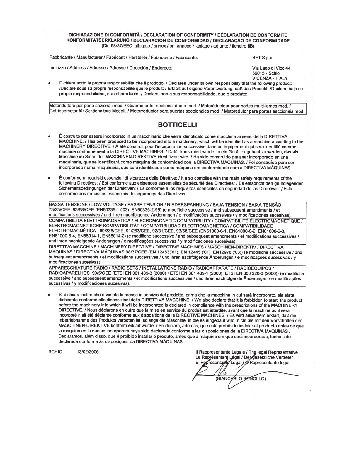
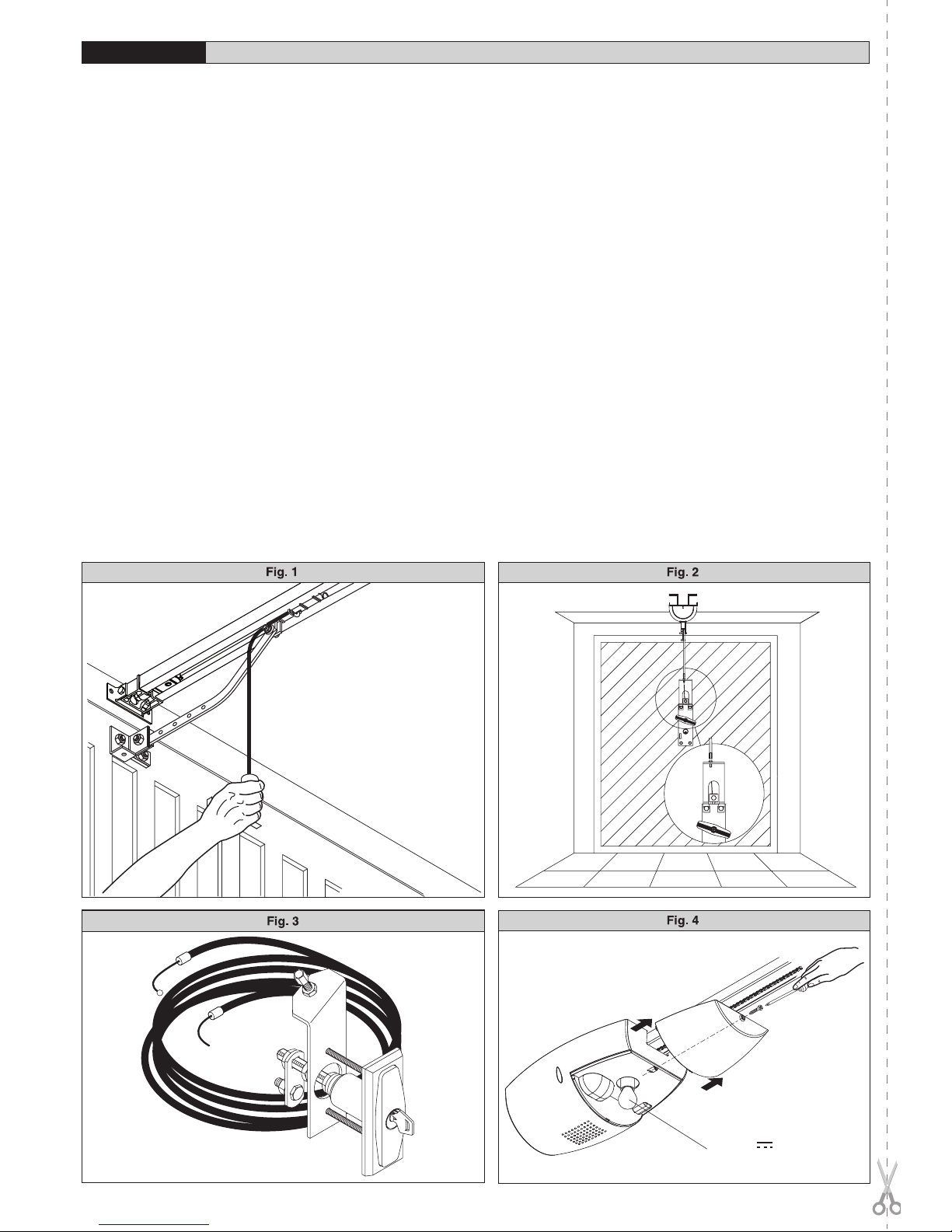
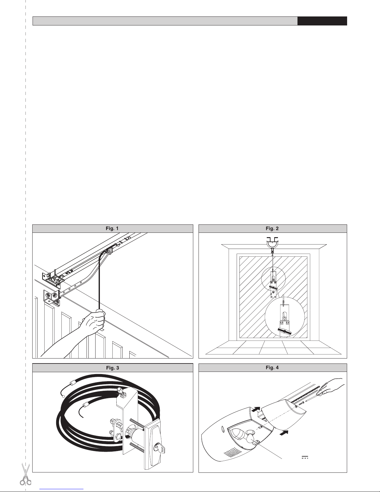
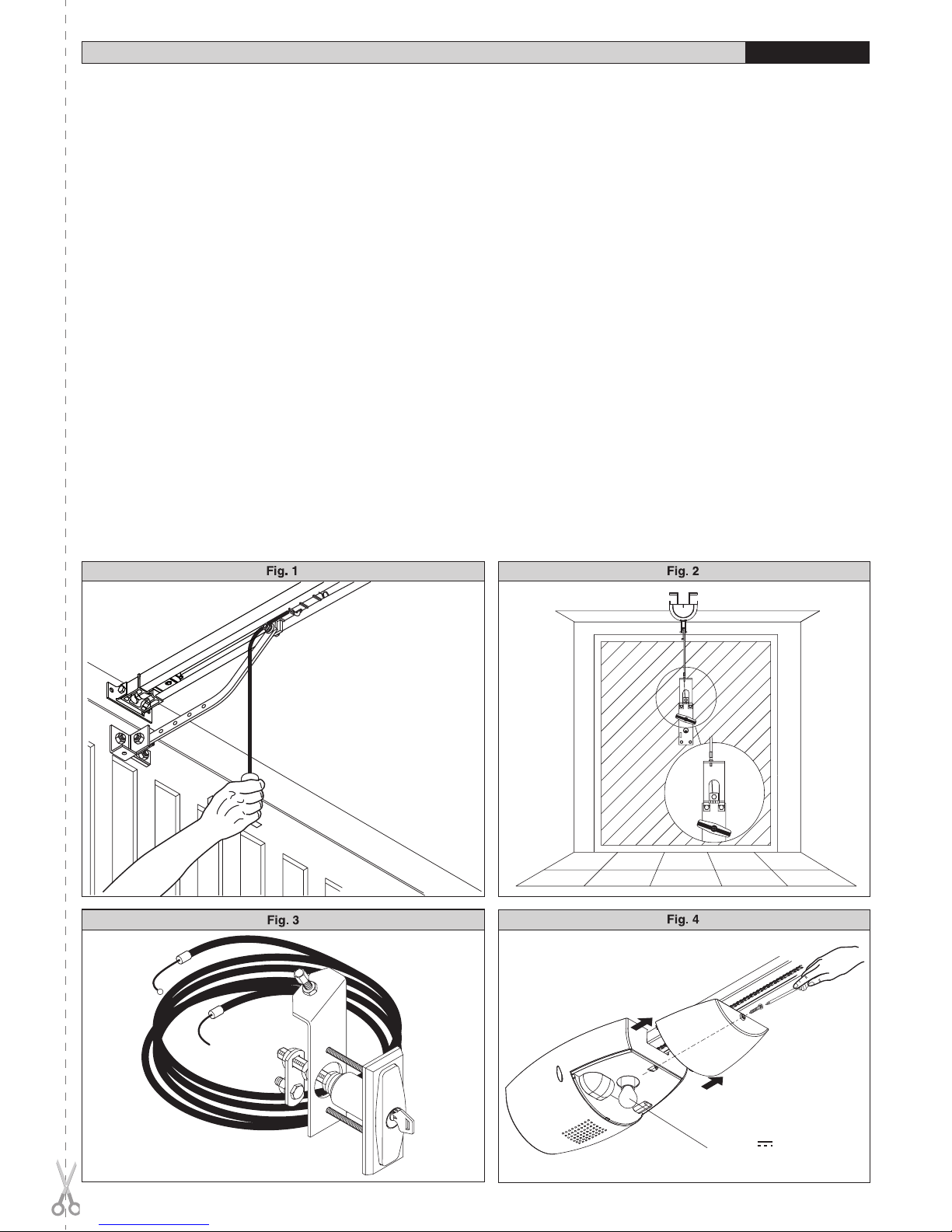
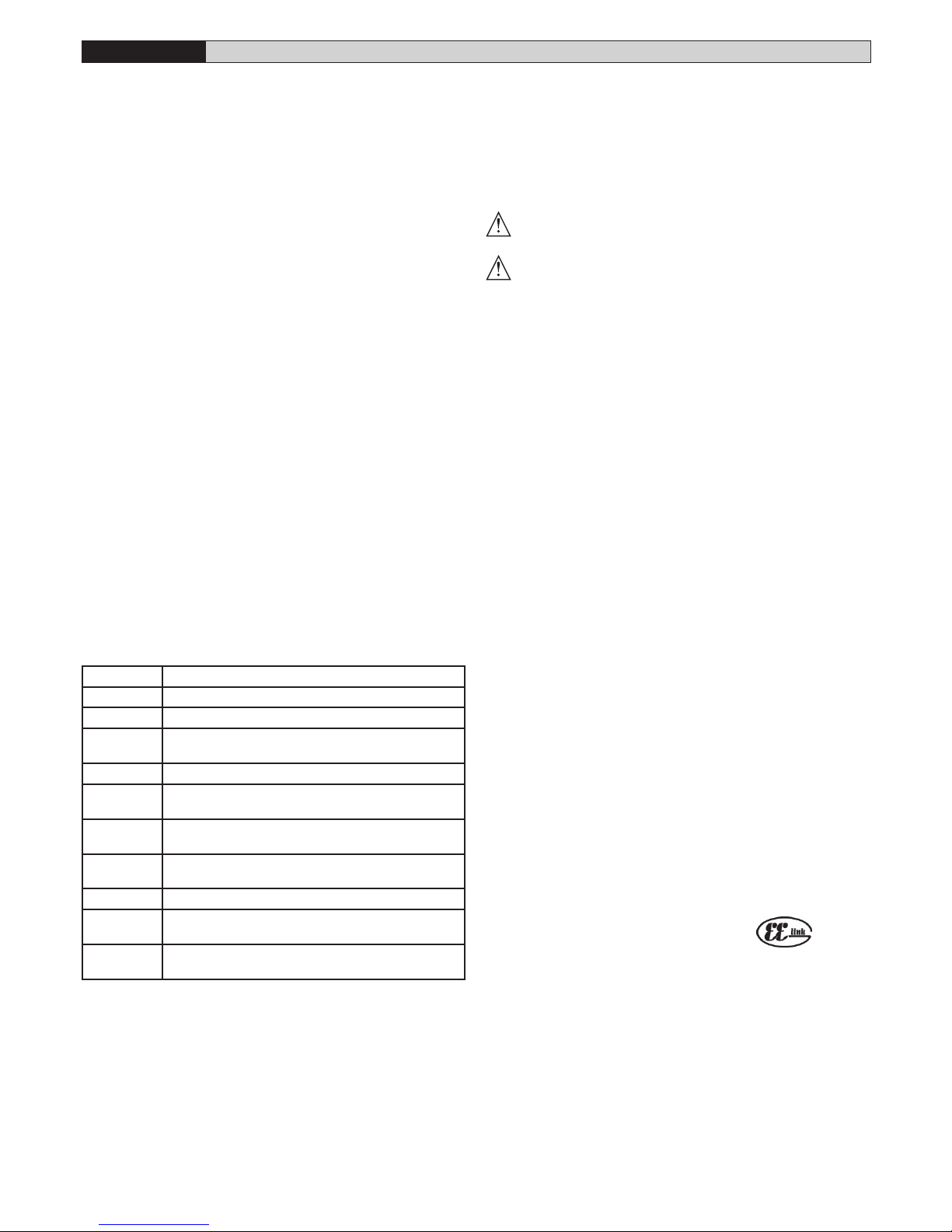
Il sistema BOTTICELLI è adatto a motorizzare porte sezionali (fig.3), porte
basculanti debordanti a molle a totale rientranza (fig.2) e porte basculanti a
contrappesi mediante un apposito braccio di traino (fig.4).L’altezza massima
della porta basculante non deve superare i 3 metri. L’installazione di facile
esecuzione, permette un rapido montaggio senza alcuna modifica alla porta.
Il blocco in chiusura è mantenuto dal motoriduttore irreversibile.
3) DATI TECNICI
3.1) Attuatore
Alimentazione:....................................230V~ ±10%, 50/60Hz Monofase (*)
Tensione motore:..............................................................................24V
Potenza max. assorbita dalla rete:......................................................236W
Lubricazione:..............................................................Grasso permanente
Forza trazione e spinta:........................................................................600N
Corsa utile:.............................BINARIO L.=2900 corsa utile=2400 mm (**).
..............................................BINARIO L.=3500 corsa utile=3000 mm (***).
Velocità media:................................................................................5 m/min
Reazione all’urto:...........Limitatore di coppia integrato su quadro comando
Manovre in 24 ore:....................................................................................20
Finecorsa:............................................................Elettronico ad ENCODER
Luce cortesia:..............................................Lampada 24V~ 25W max, E14
Temperatura di funzionamento:..............................................-15°C / +60°C
Grado di protezione:.............................................................................IPX0
Peso testa motore:.................................................................................5 kg
Rumorosità:...................................................................................<70dB(A)
Dimensioni:....................................................................................Vedi fig.1
(*) Disponibile in tutte le tensioni di rete.
(**)Ruotando la testa del motore di 90°(Fig.11), la corsa utile diventerà 2580 mm.
(***)Ruotando la testa del motore di 90°(Fig.11), la corsa utile diventerà
3180 mm.
4) INSTALLAZIONE DELL’ATTUATORE
4.1) Verifiche preliminari:
• Controllare il bilanciamento della porta.
• Controllare lo scorrimento della porta per tutta la corsa.
• Se la porta non è di nuova installazione, controllare lo stato di usura di
tutti i componenti.
• Sistemare o sostituire le parti difettose o usurate.
• L’afdabilità e la sicurezza dell’automazione è direttamente inuenzata
dallo stato della struttura della porta.
• Prima di installare il motore, togliere eventuali funi o catene superue e
disabilitare qualsiasi apparecchiatura non necessaria.
4.2) Montaggio
Tolto l’imballo ricordiamo di smaltire tutti i componenti dell’imballo, sepa-
rando i diversi tipi di materiale (cartone, polistirolo, pvc ecc.) secondo quan-
to previsto dalle norme vigenti.
1) Togliere dalla cremonese della porta il catenaccio di blocco esistente.
2) Afnchè il binario venga ssato correttamente, segnare la mezzeria
della porta, posizionare il BIN a soffitto e segnare i fori (Fig.6).
3) Forare il soffitto con una punta D.10 rispettando i riferimenti preceden-
temente segnati e inserire i tasselli fischer.
4) Bloccare il binario alla base fig.7 (rif.1-2) e fig.8 (rif.3-4-5).
5) Con l’aiuto di un appoggio adeguato, alzare l’intero motore, avvitare le
viti alla staffa porta binario senza ssarle al telaio della porta (Fig.9A)
o, se l’altezza lo consente, montare la staffa fissandola all’architrave in
muratura con tasselli (Fig.9B).
6) Alzare la testa motorizzata no ad appoggiare il tutto al softto e in-
serirvi le viti di fissaggio che bloccano il binario (comprese le viti della
staffa di ancoraggio).
7) Nel caso in cui il fissaggio della testa motore e del binario non fossero
fissati direttamente al soffitto vedere Fig.10 (bisogna sempre controllare
la planarità del binario e la sua perpendicolarità).
8) Nel caso in cui il binario fosse girato di 90° rispetto alla testa motore,
usare la dima di riferimento di Fig. 11A per tagliare il carter seguendo le
misure indicate. Per il fissaggio a soffitto del BIN vedere Fig.6 e nel caso
in cui il binario non fosse fissato direttamente al soffitto, vedere Fig.12.
9)
Nel caso in cui il binario fosse in due metà vedere Fig.13, per i vari tipi
di fissaggi vedere figure precedenti.
10) Sbloccare il carrello e fissare le staffe di ancoraggio al telo della porta
(Fig.14). La distanza fra binario e sezionale può andare da 108 a 166
mm. Se è più grande è necessario utilizzare le staffe e abbassare il
motore, se è più piccola è necessario accorciare il piatto di trascina-
mento.
11) Applicare gli adesivi forniti in prossimità dei punti pericolosi Fig.5.
BOTTICELLI VENERE - 9
D811492 00100_01

MANUALE PER L’INSTALLAZIONE
ITALIANO
5) REGOLAZIONE TENDICATENA (BOTTICELLI)
L’automazione viene fornita già tarata e collaudata. Nel caso necessiti
aggiustare la tensione della catena agire come indicato in fig.15.
ATTENZIONE: il gommino antistrappo non deve mai essere completa-
mente compresso. Verificare scrupolosamente che il gommino non
vada in totale compressione durante il funzionamento.
6) PREDISPOSIZIONE IMPIANTO ELETTRICO (Fig.16)
M) Attuatore
Ft) Fotocellula trasmittente
Fr) Fotocellule ricevente
T) Trasmittente 1-2-4 canali
Predisporre l’arrivo dei collegamenti degli accessori, dei dispositivi di
sicurezza e di comando al gruppo motore tenendo nettamente separati i
collegamenti a tensione di rete dai collegamenti in bassissima tensione di
sicurezza (24V), utilizzando l’apposito passacavo (fig.8 rif.5P1). Procedere
al loro collegamento come indicato nello schema elettrico.
I cavi di connessione accessori devono essere protetti da canaletta (fig.8
rif.5C1).
7) QUADRO COMANDO VENERE (Fig.17)
Alimentazione accessori:...............................................24V~ (180mA max)
..................................................................................24Vsafe (180mA max)
Regolazione limitatore di coppia:..............................In chiusura e apertura
Tempo di chiusura automatica:.................................................Da 3 a 120s
Collegamento lampeggiante:...............................................24V~ max 25W
Tempo di accensione lampada di servizio:.............................................90s
Radioricevente Rolling-Code incorporata:..............Frequenza 433.92 MHz
Codica:...................................................................Algoritmo Rolling-Code
N° combinazioni:............................................................................4 miliardi
Impedenza antenna:............................................................50Ohm (RG58)
N° max radiocomandi memorizzabili:.......................................................10
Spazio rallentamento:...........chiusura: ~24 cm ............... apertura: ~24 cm
Fusibili.........................................................................................vedi Fig.17
7.1) Collegamenti morsettiera (Fig.17)
AVVERTENZE - Nelle operazioni di cablaggio ed installazione riferirsi
alle norme vigenti e comunque ai principi di buona tecnica.
I conduttori alimentati a bassissima tensione di sicurezza (24V), devono
essere fisicamente separati dai conduttori a bassa tensione, oppure
devono essere adeguatamente isolati con isolamento supplementare di
almeno 1mm.
I conduttori devono essere vincolati da un fissaggio supplementare in pros-
simità dei morsetti, per esempio mediante fascette.
MORSETTO DESCRIZIONE
JP6 cablaggio trasformatore
JP7 cablaggio motore
1-2 Ingresso antenna per scheda radioricevente integrata
(1:CALZA. 2: SEGNALE)
3-4 Ingresso START (N.O.)
3-5 Ingresso STOP (N.C.) Se non si utilizza lasciare il pon-
ticello inserito.
3-6 Ingresso FOTOCELLULA (N.C.) Se non si utilizza lascia-
re il ponticello inserito.
3-7 Ingresso FAULT (N.O.)
Ingresso per fotocellule dotate di contatto N.O. di verica
8-9 Uscita 24 V~ per luce lampeggiante (25 W max)
10-11 Uscita 24V~ 180mA max - alimentazione fotocellule o
altri dispositivi.
12-13 Uscita 24V~ Vsafe 180mA max - alimentazione trasmettitori
fotocellule con verifica.
7.2) LED (Fig.17)
Le funzioni dei led sono le seguenti:
“RADIO”:Led radio ricevitore incorporato.
“SET”: Led regolazione finecorsa-presenza tensione.
7.3) SELEZIONE DIP-SWITCH (Fig.17)
DIP1) IBL - Blocca impulsi.
ON: Durante la fase di apertura non accetta i comandi di START.
OFF: Durante la fase di apertura accetta i comandi di START.
DIP2) TEST PHOT
ON: Abilita la verica delle fotocellule (è necessario l’utilizzo di fotocellule
a 5 morsetti -vedi Fig.17A-).
OFF: Disabilita la verica delle fotocellule.
7.4) REGOLAZIONE TRIMMER (Fig.17)
TCA
Regola il tempo di chiusura automatica, trascorso il quale, il cancello si
chiude automaticamente (regolabile da 3 a 120sec). Se il trimmer è ruotato
nella massima posizione, il TCA è disabilitato.
COPPIA APERTURA
Regola la sensibilità dell’amperostop in apertura.
COPPIA CHIUSURA
Regola la sensibilità dell’amperostop in chiusura.
NOTA:In caso di rilevamento ostacolo la funzione Amperostop,ferma il mo-
vimento dell’anta, inverte il moto per 1 sec. e si ferma nello stato di STOP.
ATTENZIONE: Verificare che il valore della forza d’impatto
misurato nei punti previsti dalla norma EN12445, sia inferiore
a quanto indicato nella norma EN 12453.
Una errata impostazione della sensibilità può creare
danni a persone, animali o cose.
7.5) PULSANTI
“UP”: regolazione necorsa e comando apertura. Una pressione continua
per 5 secondi comanda un autoset della coppia (Fig.19).
“DOWN”: regolazione finecorsa e comando chiusura.
“OK”: programmazione radio
8) REGOLAZIONE FINECORSA (Fig.18)
1) Premere contemporaneamente i tasti “UP” e “DOWN” per 5 secondi.
Il Led “SET” lampeggia per segnalare l’attivazione della regolazione
finecorsa.
2) Portare l’anta nella posizione di chiusura desiderata utilizzando i pulsanti
“UP” e “DOWN” della centrale, tenendo presente che il pulsante “DOWN”
chiude l’anta, mentre il pulsante “UP” apre l’anta.
3)
Appena l’anta si trova nella posizione di chiusura desiderata premere il pulsante
“OK” in modo da memorizzare la posizione di necorsa chiusura. Il Led “SET”
conferma l’avvenuta memorizzazione con un lampeggio di 1 secondo.
4) Portare l’anta nella posizione di apertura desiderata utilizzando i pulsanti
“UP” e “DOWN” della centrale, tenendo presente che il pulsante “DOWN”
chiude l’anta, mentre il pulsante “UP” apre l’anta.
5) Appena l’anta si trova nella posizione di apertura desiderata premere il
pulsante “OK” in modo da memorizzare la posizione di necorsa apertura.
Il Led “SET” conferma l’avvenuta memorizzazione con un lampeggio di
1 secondo e ritorna acceso.
6) Posizionare correttamente il“blocca carrello”a ridosso del carrello (fig.18
rif.6 A-B).
NOTA1: queste manovre vengono eseguite in modalità “uomo presente” a
velocità ridotta e senza l ’intervento delle sicurezze.
NOTA2: in caso di errori il Led “SET” rimane spento per 5 secondi.
9) AUTOSET COPPIA APERTURA / CHIUSURA (Fig.19)
1) Dalla posizione di necorsa di chiusura, premere il pulsante “UP” per 5
secondi.
2) Il Led “SET” lampeggia velocemente e l’anta inizia un’ apertura. Fino al
raggiungimento del finecorsa di apertura.
3) Attesa di 3 secondi.
4) Il Led “SET” lampeggia velocemente e l’anta inizia una chiusura. Fino al
raggiungimento del finecorsa di chiusura.
5) Al termine dell’autoset regolare i trimmer opening/closing torque in maniera
tale da ottenere la sensibilità all’ostacolo desiderata.
Qualsiasi attivazione di un ingresso (START, RADIOCOMANDO, STOP,
FOTOCELLULA) durante le manovre di autoset annulla l’autoset stesso.
10) RICEVITORE INTEGRATO
Versioni trasmettitori utilizzabili:
Tutti i trasmettitori ROLLING CODE compatibili con .
10.1) INSTALLAZIONE ANTENNA
Usare una antenna accordata sui 433MHz.
Per il collegamento Antenna-Ricevitore usare cavo coassiale RG58.
La presenza di masse metalliche a ridosso dell’antenna, può disturbare la
ricezione radio. In caso di scarsa portata del trasmettitore, spostare l’antenna
in un punto più idoneo.
10.2) PROGRAMMAZIONE TRASMETTITORI MANUALE (Fig. 20)
1) Premere il pulsante “OK” nella centralina.
2) Al lampeggio del Led “RADIO” premere il tasto nascosto P1 del trasmet-
titore, il Led “RADIO” resterà acceso sso.
3) Premere il tasto da memorizzare del trasmettitore, il led “RADIO” rico-
mincerà a lampeggiare.
4) Per memorizzare un ulteriore trasmettitore ripetere i passi 2) e 3).
5) Per uscire dal modo di memorizzazione attendere fino al completo spe-
gnimento del led.
10 - BOTTICELLI VENERE
D811492 00100_01

10.3) PROGRAMMAZIONE TRASMETTITORI REMOTA (Fig. 20)
1) Premere il tasto nascosto (P1) di un trasmettitore già memorizzato in
modalità standard attraverso la programmazione manuale.
2) Premere iltastonormale(T1-T2-T3-T4)di un trasmettitore giàmemorizzato
in modalità standard attraverso la programmazione manuale.
3) La lampada di cortesia lampeggia. Premere entro 10s il tasto nascosto
(P1) di un trasmettitore da memorizzare.
4) La lampada di cortesia rimane accesa fissa. Premere il tasto normale
(T1-T2-T3-T4) di un trasmettitore da memorizzare.
La ricevente esce dalla modalità programmazione dopo 10s, entro questo
tempo è possibile inserire ulteriori nuovi trasmettitori.
Questa modalità non richiede l’accesso al quadro di comando.
10.4) CANCELLAZIONE TRASMETTITORI (Fig. 20)
Per cancellare totalmente la memoria della centralina premere per 10
secondi il pulsante “OK” nella centralina (il led “RADIO” lampeggia). La cor-
retta cancellazione della memoria sarà segnalata dal Led “RADIO” acceso
fisso. Per uscire dal modo di memorizzazione attendere fino al completo
spegnimento del led.
11) MANOVRA DI EMERGENZA
Nel caso manchi l’energia elettrica o, di avaria del sistema, per eseguire la
manovra manualmente, bisogna tirare il cordino collegato al carrello come
in fig.21. Per autorimesse prive di uscita secondaria è obbligatorio montare
un dispositivo di sblocco dall’esterno con chiave tipo il Mod.SM1 (fig.22) o
il Mod.SET/S (fig.23).
12) VERIFICA DELL’AUTOMAZIONE
Prima di rendere definitivamente operativa l’automazione, controllare
scrupolosamente quanto segue:
• Controllare il corretto funzionamento di tutti i dispositivi di sicurezza (mi-
cro-finecorsa, fotocellule, coste sensibili ecc.).
• Vericare che la spinta (antischiacciamento) della porta sia entro i limiti
previsti dalle norme vigenti e comunque non troppo elevata rispetto alle
condizioni di installazione ed uso.
• Vericare che il gommino tendicatena non si comprima completamente
durante la manovra.
• Vericare il comando di apertura manuale.
• Vericare l’operazione di apertura e chiusura con i dispositivi di comando
applicati.
•
Verificare la logica elettronica di funzionamento normale e personalizzata.
13) USO DELL’AUTOMAZIONE
Poiché l’automazione può essere comandata a distanza mediante radioco-
mando o pulsante di start, e quindi non a vista, è indispensabile controllare
frequentemente la perfetta efficienza di tutti i dispositivi di sicurezza. Per
qualsiasi anomalia di funzionamento, intervenire rapidamente avvalendosi
anche di personale qualificato. Si raccomanda di tenere i bambini a debita
distanza dal raggio d’azione dell’automazione.
14) COMANDO
L’utilizzo dell’automazione consente l’apertura e la chiusura della porta in
modo motorizzato. Il comando può essere di diverso tipo (manuale, con
radiocomando, controllo accessi con tessera magnetica ecc.) secondo le
necessità e le caratteristiche dell’installazione.Per i vari sistemi di comando,
vedere le relative istruzioni. Gli utilizzatori dell’automazione devono essere
istruiti al comando e all’uso.
15) ACCESSORI
SM1 Sblocco esterno da applicare alla cremonese esistente della porta
basculante (fig.22).
SET/S Sblocco esterno a maniglia rientrante per porte sezionali max. 50mm
(fig.23).
ST Sblocco automatico catenacci per porte basculanti a molle. Applicato
albraccettodi comando,sgancia automaticamenteicatenaccilaterali
della porta (fig.24).
16) MANUTENZIONE
Per qualsiasi manutenzione, togliere alimentazione al sistema.
• Vericare periodicamente (2 volte l’anno) il tensionamento della catena/
cinghia.
•
Eseguire saltuariamente la pulizia delle ottiche delle fotocellule se installate.
• Far controllare da personale qualicato (installatore) la corretta regolazione
della frizione elettronica.
• Per qualsiasi anomalia di funzionamento, non risolta, togliere alimentazione
al sistema e richiedere l’intervento di personale qualificato (installatore).
Nel periodo di fuori servizio, attivare lo sblocco manuale per consentire
l’apertura e la chiusura manuale.
Se il cavo di alimentazione è danneggiato, esso deve essere sostituito
dal costruttore o dal suo servizio assistenza tecnica o comunque da
persona con qualifica similare, in modo da prevenire ogni rischio.
16.1) SOSTITUZIONE FUSIBILE
ATTENZIONE! Scollegare la tensione di rete.
Togliere dal porta fusibile la protezione in gomma. Rimuovere il fusibile (Fig.
Rif.A) da cambiare e sostituirlo con il nuovo. A operazione conclusa, inserire
nuovamente la protezione in gomma.
17) DEMOLIZIONE
Attenzione: Avvalersi esclusivamente di personale qualificato.
L’eliminazione dei materiali va fatta rispettando le norme vigenti.
Nel caso di demolizione dell’automazione non esistono particolari pericoli
o rischi derivanti dall’automazione stessa.
È opportuno, in caso di recupero dei materiali, che vengano separati per
tipologia (parti elettriche - rame - alluminio - plastica - ecc.).
18) SMANTELLAMENTO
Attenzione: Avvalersi esclusivamente di personale qualicato.
Nel caso l’automazione venga smontata per essere poi rimontata in altro
sito bisogna:
• Togliere l’alimentazione e scollegare tutto l’impianto elettrico esterno.
• Nel caso alcuni componenti non possano essere rimossi o risultino
danneggiati, provvedere alla loro sostituzione.
Le descrizioni e le illustrazioni del presente manuale non sono impe-
gnative. Lasciando inalterate le caratteristiche essenziali del prodotto,
la Ditta si riserva di apportare in qualunque momento le modifiche che
essa ritiene convenienti per migliorare tecnicamente, costruttivamente
e commercialmente il prodotto, senza impegnarsi ad aggiornare la
presente pubblicazione.
MANUALE PER L’INSTALLAZIONE ITALIANO
BOTTICELLI VENERE - 11
D811492 00100_01

INSTALLATION MANUAL
ENGLISH
Thank you for buying this product, our company is sure that you will be more
than satisfied with the product’s performance.The product is supplied with a
“Warnings” leaet and an “Instruction booklet”. These should both be read
carefully as they provide important information about safety, installation,
operation and maintenance. This product complies with the recognised
technical standards and safety regulations. We declare that this product is in
conformity with the following European Directives: 89/336/EEC, 73/23/EEC,
98/37/EEC, 99/05/EEC (and subsequent amendments).
1) GENERAL SAFETY
WARNING! An incorrect installation or improper use of the product can cause
damage to persons, animals or things.
• The “Warnings” leaet and “Instruction booklet” supplied with this product
should be read carefully as they provide important information about
safety, installation, use and maintenance.
• Scrap packing materials (plastic, cardboard, polystyrene etc) according
to the provisions set out by current standards. Keep nylon or polystyrene
bags out of children’s reach.
• Keep the instructions together with the technical brochure for future
reference.
• This product was exclusively designed and manufactured for the use
specied in the present documentation. Any other use not specied in
this documentation could damage the product and be dangerous.
• The Company declines all responsibility for any consequences result-
ing from improper use of the product, or use which is different from that
expected and specied in the present documentation.
• Do not install the product in explosive atmosphere.
• The construction components of this product must comply with the following
European Directives: 89/336/CEE, 73/23/EEC, 98/37/EEC and subse-
quent amendments. As for all non EEC countries, the abovementioned
standards as well as the current national standards should be respected
in order to achieve a good safety level.
• The Company declines all responsibility for any consequences resulting
from failure to observe Good Technical Practice when constructing clos-
ing structures (door, gates etc.), as well as from any deformationwhich
might occur during use.
• The installation must comply with the provisions set out by the followingEu-
ropean Directives:89/336/CEE, 73/23/EEC, 98/37/EEC and subsequent
amendments.
• Disconnect the electrical power supply before carrying out any work on
the installation. Also disconnect any buffer batteries, if tted.
• Fit an omnipolar or magnetothermal switch on the mains power supply,
having a contact opening distance equal to or greater than 3,5 mm.
• Check that a differential switch with a 0.03A threshold is tted just before
the power supply mains.
• Check that earthing is carried out correctly: connect all metal parts for
closure (doors, gates etc.) and all system components provided with an
earth terminal.
• Fit all the safety devices (photocells, electric edges etc.) which are needed
to protect the area from any danger caused by squashing, conveying and
shearing.
• Position at least one luminous signal indication device (blinker) where it
can be easily seen, and x a Warning sign to the structure.
• The Company declines all responsibility with respect to the automation safety
and correct operation when other manufacturers’ components are used.
• Only use original parts for any maintenance or repair operation.
• Do not modify the automation components, unless explicitly authorised
by the company.
• Instruct the product user about the control systems provided and the
manual opening operation in case of emergency.
• Do not allow persons or children to remain in the automation operation
area.
• Keep radio control or other control devices out of children’s reach, in
order to avoid unintentional automation activation.
• The user must avoid any attempt to carry out work or repair on the automa-
tion system, and always request the assistance of qualified personnel.
• Anything which is not expressly provided for in the present instructions,
is not allowed.
• Installation must be carried out using the safety devices and controls
prescribed by the EN 12978 Standard.
• Fit any xed control within sight of the door but away from moving parts,
higher than 1.5 m.
• Add a label bearing the following notices:
“Keep children away from the moving door”.
“WARNING: risk of squashing”.
Regularly check that the door reverses its movement when colliding with an
obstacle 50 mm away from the floor and, if necessary, set it correctly.
2) GENERAL OUTLINE
The BOTTICELLI system is suitable for motorising sectional doors (g. 3),
protruding fully retracting spring-operated overhead doors (fig.2) and coun-
terweight overhead doors provided with an appropriate towing arm (fig. 4).
The overhead door must not be higher than 3 metres. Its easy installation
allows fast fitting without needing the door to be modified. The irreversible
gearmotor keeps the door locked in the closing position.
3) TECHNICAL SPECIFICATIONS
3.1) Actuator
Power supply:..................................230V~±10%, 50/60Hz single-phase (*)
Motor voltage:........................................................................................24V
Max. power absorbed from mains:......................................................236W
Lubrication:......................................................................permanent grease
Towing and pushing force:...................................................................600N
Working stroke:....................TRACK L.=2900 working stroke=2400 mm(**)
............................................TRACK L.=3500 working stroke=3000 mm(***)
Average speed:................................................................................5 m/min
Impact reaction:............................integrated torque limiter on control panel
Manoeuvres in 24 hours:..........................................................................20
Limit switch:........................................................Electronic with ENCODER
Courtesy light:......................................................24V~ 25W max, E14 bulb
Working temperature:.............................................................-15°C / +60°C
Degree of protection:............................................................................IPX0
Motor head weight:.................................................................................5kg
Noise level:....................................................................................<70dB(A)
Dimensions:....................................................................................see fig.1
(*) Available in all mains voltages.
(**)By turning the motor head by 90° (Fig.11) the useful stroke will be 2580 mm.
(***) By turning the motor head by 90° (Fig.11) the useful stroke will be 3180 mm.
4) ACTUATOR INSTALLATION
4.1) Preliminary checks
• Check that the door is balanced.
• Check that the door slides smoothly along its entire travel.
• If the door has not been newly installed, check the wear condition of all
its components.
• Repair or replace faulty or worn parts.
• The automation reliability and safety are directly inuenced by the state
of the door structure.
• Before tting the motor, remove any superuous ropes or chains and
disable any unnecessary appliances.
4.2) FITTING
After unpacking, dispose of the parts which make up the package properly,
by separating the different type of materials (cardboard, polystyrene, PVC,
etc.) according to the national rules in force.
1) Remove the existing locking bolt from the cremone bolt of the door.
2) In order to x the track correctly, mark the mid-point of the door, posi-
tion the BIN on the ceiling and mark the holes (Fig. 6).
3) Drill the ceiling with a 10-dia. drill bit following the previously made
marks, and insert the Fischer plugs.
4) Secure the track at the base, fig.7 (ref.1-2) and fig.8 (ref.3-4-5).
5) With the help of an adequate support, lift the entire motor, screw the
screws onto the track-holding bracket without xing them to the door
frame (Fig.9A) or, if the height allows it, t the bracket to the masonry
lintel by means of plugs (Fig.9B).
6) Lift the motor-driven head until everything rests against the ceiling, and
insert the xing screws which lock the track (including the anchoring
bracket screws).
7) If the motor head and the track are not xed directly to the ceiling, see
Fig.10 (always check that the track is level and perpendicular to the cei-
ling).
8) In the case where the track is turned by 90° with respect to the motor
head, use the reference template in Fig. 11A to cut out the guard, keep-
ing to the measurements indicated. For xing the BIN to the ceiling, see
Fig.6 and in case the track is not xed directly to the ceiling, see Fig.12.
9) In the case where the track is made in two halves, see Fig.13; for the
different types of xing methods, see the previous gures.
10)
Release the carriage and x the anchoring brackets to the door panel
(Fig.14). The distance allowed between track and sectional door is 108
to 166 mm. In case of greater distance, it is necessary to use the brac-
kets and lower the motor; in case of shorter distance, it is necessary to
shorten the towing plate.
11)
Stick the adhesive labels supplied next to the dangerous points (Fig. 5).
5) CHAIN TIGHTENER ADJUSTMENT (BOTTICELLI)
The operator supplied is already calibrated and inspected.Should the chain
tension need to be adjusted, proceed as shown in fig. 15.
12 - BOTTICELLI VENERE
D811492 00100_01

INSTALLATION MANUAL ENGLISH
WARNING: the anti-tear rubber element must never be completely
compressed. Scrupulously check that the rubber does not become
totally compressed during operation.
6) ELECTRICAL INSTALLATION SET-UP (Fig.16)
M) Actuator
Ft) Transmitter photocell
Fr) Receiver photocells
T) 1-2-4 channel transmitter.
Arrange for the connections of accessories and safety and control devices
to reach the motor unit, keeping the mains voltage connections clearly
separate from the extra low safety voltage connections (24V) by means of
the appropriate cable holder (fig. 8 ref. 5P1).
Proceed to connection following the indications given in the wiring diagram.
The cables for connecting the accessories must be protected by a raceway
(fig. 8 ref. 5C1).
7) VENERE Control panel (Fig.17)
Supply to accessories: ..................................................24V~ (180mA max)
.............................................................24V~ Vsafe VENERE (180mA max)
Torque limiter setting:..............................................on closing and opening
Automatic closing time:.........................................................from 3 to 120s
Blinker connection:..............................................................24V~ max 25W
Service light switching-on time:..............................................................90s
Incorporated rolling-code radio receiver:..................frequency 433.92 MHz
Coding:.......................................................................rolling-code algorithm
No. combinations:...........................................................................4 milliard
Antenna impedance:............................................................50Ohm (RG58)
Max no. radio controls to be memorised:..................................................10
Slow-down distance:................closing: ~24 cm ............... opening: ~24 cm
Fuses:......................................................................................see figure 17
7.1) Terminal board connections (Fig.17)
WARNINGS - For wiring and installation operations, refer to the current
standards and good technical principles.
The wires supplied with extra low safety voltage (24V) must be kept physi-
cally separate from the low voltage wires, or else they must be provided with
adequate additional insulation of at least 1mm.
The wires must be clamped by an extra fastener near the terminals, for
example by bands.
TERMINAL DESCRIPTION
JP6 transformer wiring
JP7 motor wiring
1-2 Antenna input for integrated radio-receiver board
(1: BRAID. 2: SIGNAL)
3-4 START input (N.O.)
3-5 STOP input (N.C.) If not used, leave the jumper inserted.
3-6 PHOTOCELL input (N.C.) If not used, leave the jumper
inserted.
3-7 FAULT input (N.O.)
Input for photocells provided with checking N.O. contact
8-9 24 V~ output for blinking light (25 W max)
10-11 24V~ 180mA max output – power supply for photocells
or other devices
12-13 24V~ Vsafe 180mA max output – power supply for checking
photocell transmitters.
7.2) LED (Fig.17)
The led functions are as follows:
“RADIO”:Incorporated radio-receiver led.
“SET”: Limit device setting led - power ON.
7.3) DIP-SWITCH SELECTION (Fig.17)
DIP1) IBL – Locks impulses.
ON: During the opening phase, does not accept START commands.
OFF: During the opening phase, accepts START commands.
DIP2) TEST PHOT
ON: Enables photocell checking (5-connector photocells must be used
- see Fig.17A-).
OFF: Disables photocell checking.
7.4) TRIMMER SETTING (Fig.17)
TCA
Sets the automatic closing time, after which the gate closes automatically
(can be set from 3 to 120 sec). If the trimmer is turned all the way, the TCA
is disabled.
OPENING TORQUE
Sets the ampere-stop sensitivity on opening.
CLOSING TORQUE
Sets the ampere-stop sensitivity on closing.
NOTE: In case of obstacle detection, the Ampere-stop function halts
the leaf movement, reverses the motion for 1 sec. and stays in the
STOP state.
WARNING: check that the impact force value measured at the
points established by the EN 12445 standard is lower than that
specified in the EN 12453 standard.
Incorrect sensitivity setting can cause injuries to persons or ani-
mals, or damage to things.
7.5) BUTTONS
“UP”: limit device setting and opening command. An autoset operation
of the torque will be performed by keeping this button pressed
for 5 seconds (Fig.19).
“DOWN”: limit device setting and closing command.
“OK”: radio programming.
8) LIMIT DEVICE SETTING (Fig.18)
1) Simultaneously press the “UP” and “DOWN” keys for 5 seconds. The
“SET” led blinks to indicate that the limit device setting is activated.
2) Bring the leaf to the required closing position, using the “UP” and “DOWN”
buttons on the control unit, and keeping in mind that the “DOWN” button
closes the leaf, while the “UP” button opens the leaf.
3) As soon as the leaf reaches the required closing position, press the “OK”
button in order to memorise the limit device closing position. The “SET”
led confirms data storage by blinking for 1 second.
4) Bring the leaf to the required opening position, using the “UP” and “DOWN”
buttons on the control unit, and keeping in mind that the “DOWN” button
closes the leaf, while the “UP” button opens the leaf.
5) As soon as the leaf reaches the required opening position, press the
“OK” button in order to memorise the limit device opening position. The
“SET” led confirms data storage by blinking for 1 second and then lits up
again.
6) Correctly position the “carriage lock” against the carriage (g.18 ref.6 A-B).
NOTE 1: These manoeuvres are carried out in “hold-to-run”mode at reduced
speed and with no safety devices activated.
NOTE 2: In case of errors, the “SET” led remains off on for 5 seconds.
9) OPENING / CLOSING TORQUE AUTOSETTING (Fig.19)
1) After reaching the closing end-of-stroke position, press the “UP” button
for 5 seconds.
2) The “SET” led blinks rapidly and the leaf starts to open until it reaches
the opening end-of-stroke.
3) 3 second down time.
4) The “SET” led blinks rapidly and the leaf starts to close until it reaches
the closing end-of-stroke
5) After completing the autoset adjust the opening/closing torque trimmers
so as to obtain the desired sensitivity to the obstacle.
Anyinput activation(START,RADIOTRANSMITTER,STOP,PHOTOCELL)
during autosetting will annul the autoset in progress.
10) INTEGRATED RECEIVER
Transmitter versions which can be used:
all Rolling Code transmitters compatible with .
10.1)ANTENNA INSTALLATION
Use an antenna tuned to 433MHz.
For Antenna-Receiver connection, use RG8 coaxial cable.
The presence of metallic masses next to the antenna can interfere with radio
reception. In case of insufficient transmitter range, move the antenna to a
more suitable position.
10.2) MANUAL TRANSMITTER PROGRAMMING (Fig.20)
1) Press the “OK” button on the control unit.
2) When the “RADIO” LED blinks, press the transmitter P1 hidden key, and
the “RADIO” LED will stay on permanently.
3) Press the key to be memorised on the transmitter, LED “RADIO” will start
blinking again.
4) To memorise another transmitter, repeat steps 2) and 3).
5) To exit the storage mode, wait until the LED is switched off completely.
BOTTICELLI VENERE - 13
D811492 00100_01

INSTALLATION MANUAL
ENGLISH
10.3) REMOTE TRANSMITTER PROGRAMMING (Fig.20)
1) Press the hidden key (P1) of a transmitter that has been already memo-
rised in standard mode by means of manual programming.
2) Press the normal key (T1-T2-T3-T4) of a transmitter that has been already
memorised in standard mode by means of manual programming.
3) The courtesy lamp blinks. Press the hidden key (P1) of a transmitter to
be memorised within 10s.
4) The courtesy lamp stays on permanently. Press the normal key (T1-T2-
T3-T4) of a transmitter to be memorised.
The receiver exits the programming mode within 10s., within this time new
additional transmitters can be memorised.
This mode does not require access to the control panel.
10.4) TRANSMITTER CANCELLATION (Fig.20)
To cancel the control unit memory totally, press the “OK” button on the control
unit for 10 seconds (“RADIO” LED blinking). Correct memory cancellation
will be indicated by the “RADIO” LED staying on permanently. To exit the
storage mode, wait until the LED is switched off completely.
11) EMERGENCY MANOEUVRE
In case of electric power failure or system malfunction, the manoeuvre
must be carried out manually by pulling the wire connected to the carriage,
as in g.21. For garages which are not provided with a second exit, it is
compulsory to t an external key release device like Mod. SM1 (fig.22) or
Mod. SET/S (fig.23).
12) AUTOMATION CHECK
Before the automation devicefinally becomes operational, scrupulously
check the following conditions:
• Check that all the safety devices (limit microswitches, photocells, electric
edges etc) operate correctly.
• Check that the door (antisquash) thrust is comprised within the limits set
out by the current standards, and anyway not too strong for the installation
and operating conditions.
• Check that the chain-tightening rubber element is not completely com-
pressed during the manoeuvre.
• Check the manual opening control operation.
•
Check the opening and closing operations using the control devices fitted.
• Check the normal and customised operation electronic logics.
13) AUTOMATION DEVICE USE
Since the automation device can be remotely controlled by means of a ra-
dio control device or a Start button, and therefore when not in sight, all the
safety devices must be frequently checked in order to ensure their perfect
efficiency. In the event of any malfunction, request immediate assistance
from qualified personnel. Children must be kept at a safe distance from the
automation operation area.
14) AUTOMATION CONTROL
The use of this control device allows the gate to be opened and closed
automatically. There are different types of controls (manual, radio control,
magnetic card access etc.) depending on the installation requirements and
characteristics.For the various control systems, see the relevant instructions.
The automation device users must be instructed on control and operation.
15) ACCESSORIES
SM1 External release device to be applied to the cremone bolt already
fitted to the overhead door (fig.22).
SET/S External release device with retracting handle for sectional doors
measuring max 50mm (fig.23).
ST Automatic bolt release device for spring-operated overhead doors.
Fitted to the control arm, it automatically releases the side door bolts
(fig.24).
16) MAINTENANCE
Before carrying out any maintenance operation, disconnect the system
power supply.
• Periodically check the tension of the chain/belt (twice a year).
• Occasionally clean the photocell optical elements, if installed.
• Have a qualied technician (installer) check the correct setting of the
electronic clutch.
• When any operational malfunction if found, and not resolved, disconnect
the system power supply and request the assistance of a qualified techni-
cian (installer). When the product is out of service, activate the manual
release device to allow the door to be opened and closed manually.
If the power supply cable is damaged, it must be replaced directly by
our company or our technical service department or by a technician
having similar qualification so as to avoid any risks.
16.1) FUSE REPLACEMENT (Fig.25)
WARNING! Disconnect the mains voltage.
Remove the rubber protection from the fuse-carrier. Remove the fuse (Fig.25,
Ref.A) to be replaced and replace it with a new one. After completing this
operation, re-fit the rubber protection.
17) SCRAPPING
Warning! This operation should only be carried out by qualified per-
sonnel.
Materials must be disposed of in conformity with the current regulations.
In case of scrapping, the automation devices do not entail any particular risks
or danger. In case of materials to be recycled, these should be sorted out by
type (electrical components, copper, aluminium, plastic etc.).
18) DISMANTLING
Warning! This operation should only be carried out by qualied personnel.
When the automation system is disassembled to be reassembled on another
site, proceed as follows:
• Disconnect the power supply and the entire external electrical installa-
tion.
• In the case where some of the components cannot be removed or are
damaged, they must be replaced.
The descriptions and illustrations contained in the present manual are
not binding. The Company reserves the right to make any alterations
deemed appropriate for the technical, manufacturing and commercial
improvement of the product, while leaving the essential product fea-
tures unchanged, at any time and without undertaking to update the
present publication.
14 - BOTTICELLI VENERE
D811492 00100_01

MANUEL D’INSTALLATION FRANÇAIS
Nous vous remercions pour avoir choisi ce produit. Nous sommes certains
qu’il vous offrira les performances que vous souhaitez. Lisez attentivement
la brochure “Avertissements” et le “Manuel d’instructions” qui accompagnent
ce produit, puisqu’ils fournissent d’importantes indications concernant la
sécurité, l’installation, l’utilisation et l’entretien. Ce produit est conforme aux
règles reconnues de la technique et aux dispositions de sécurité. Nous certi-
fions sa conformité avec les directives européennes suivantes: 89/336/CEE,
73/23/CEE, 98/37/CEE, 99/05/CEE (et modifications successives).
1) SECURITE GENERALE
ATTENTION! Une installation erronée ou une utilisation impropre du
produit peuvent provoquer des lésions aux personnes et aux animaux
ou des dommages aux choses.
• Lisez attentivement la brochure “Avertissements” et le “Manuel d’instruc
tions” qui accompagnent ce produit, puisqu’ils fournissent d’importantes
indications concernant la sécurité, l’installation, l’utilisation et l’entretien.
• Eliminer les matériaux d’emballage (plastique, carton, polystyrène etc.)
selon les prescriptions des normes en vigueur. Ne pas laisser des envelop
pes en nylon et polystyrène à la portée des enfants.
• Conserver les instructions et les annexer à la che technique pour les
consulter à tout moment.
• Ce produit a été conçu et réalisé exclusivement pour l’utilisation indiquée
dans cette documentation. Des utilisations non indiquées dans cette
documentation pourraient provoquer des dommages au produit et repré
senter une source de danger pour l’utilisateur.
• La Société décline toute responsabilité dérivée d’une utilisation impropre
ou différente de celle à laquelle le produit a été destiné et qui est indiquée
dans cette documentation.
• Ne pas installer le produit dans une atmosphère explosive.
•
Les éléments constituant la machine doivent être conformes aux Directives
Européennessuivantes:89/336/CEE,73/23/CEE,98/37/CEEetmodifications
succes sives. Pour tous les Pays en dehors du Marché Commun, outre aux
normes nationales en vigueur il est conseillé de respecter également les
normes indiquées ci haut afin d’assurer un bon niveau de sécurité.
• La Société décline toute responsabilité en cas de non respect des règles de
bonne technique dans la construction des fermetures (portes, portails etc.),
ainsi qu’en cas de déformations pouvant se produire pendant l’utilisation.
• L’installation doit être conforme aux prescriptions des Directives Européen-
nes: 89/336/CEE, 73/23/CEE, 98/37/CEE et modifications successives.
•
Couperl’alimentationélectriqueavantd’effectuern’importequelleintervention
sur l’installation. Débrancher aussi les éventuelles batteries de secours.
• Prévoir sur la ligne d’alimentation de la motorisation un interrupteur ou un
magnétothermique omnipolaire avec distance d’ouverture des contacts
égale ou supérieure à 3,5 mm.
• Vérier qu’en amont de la ligne d’alimentation il y a un interrupteur diffé-
rentiel avec seuil de 0,03A.
• Vérier si l’installation de terre est effectuée correctement: connecter toutes
les parties métalliques de la fermeture (portes, portails etc.) et tous les
composants de l’installation dotés de borne de terre.
• Appliquer tous les dispositifs de sécurité (cellules photoélectriques, barres
palpeuses etc.) nécessaires à protéger la zone des dangers d’écrasement,
d’entraînement, de cisaillement.
• Appliquer au moins un dispositif de signalisation lumineuse (feu clignotant)
en position visible, xer à la structure un panneau de Attention.
• La Société décline toute responsabilité en matière de sécurité et de bon fonction-
nement de la motorisation si des composants d’autres producteurs sont utilisés.
• Utiliser exclusivement des pièces originales pour n’importe quel entretien
ou réparation.
• Ne pas effectuer des modications aux composants de la motorisation si
non expressément autorisées par la Société.
• Informer l’utilisateur de l’installation sur les systèmes de commande appli
qués et sur l’exécution de l’ouverture manuelle en cas d’urgence.
• Ne pas permettre à des personnes et à des enfants de stationner dans la
zone d’action de la motorisation.
• Ne pas laisser des radio commandes ou d’autres dispositifs de commande
à portée des enfants afin d’éviter des actionnements involontaires de la
motorisation.
• L’utilisateur doit éviter toute tentative d’intervention ou de réparation de la
motorisation et ne doit s’adresser qu’à du personnel qualifié.
•
Tout ce qui n’est pas expressément prévu dans ces instructions, est interdit.
• L’installation doit être faite en utilisant des dispositifs de sécurité et des
commandes conformes à la norme EN 12978.
• Installer toutes les commandes xes en vue de la porte mais loin des
parties mobiles et à une hauteur supérieure à 1,5 m.
• Ajouter une étiquette qui contient les phrases suivantes:
“Tenir les enfants loin de la porte en mouvement”.
“ATTENTION: risque d’écrasement: contrôler régulièrement que la porte
inverse le mouvement quand elle heurte un obstacle d’une hauteur de 50 mm
en partant du sol et si cela est nécessaire, effectuer le réglage correct.
2) GENERALITES
Le système BOTTICELLI est indiqué pour motoriser des portes multi-lames
(fig. 3), des portes de garage débordantes à ressorts complètement esca-
motables (fig.2) et des portes de garage à contrepoids, au moyen d’un bras
d’entraînement spécial (fig. 4).
La hauteur maximale de la porte de garage ne doit pas dépasser 3 mètres.
L’installation, très facile à effectuer, permet un montage rapide sans aucune
modification de la porte. Le blocage en fermeture est maintenu par le mo-
toréducteur irréversible.
3) CARACTERISTIQUES TECHNIQUES
3.1) Opérateur
Alimentation:..................................230V~ ±10%, 50/60Hz Monophasée (*)
Tension du moteur:...........................................................................24V
Puissance maxi absorbée par le réseau:............................................236W
Lubrication: ................................................................Graisse permanente
Force de traction et de poussée:..........................................................600N
Course utile: ................................RAIL L.=2900 course utile=2400 mm (**)
...................................................RAIL L.=2900 course utile=2400 mm (***)
Vitesse moyenne:............................................................................5 m/min
Réaction à l’impact:.Limiteur de couple intégré sur centrale de commande
Manoeuvres en 24 heures:.......................................................................20
Fin de course:..................................................Électronique avec CODEUR
Lumière de courtoisie:................................ampoule 24V~ 25W maxi, E14
Température de fonctionnement:............................................-15°C / +60°C
Degré de protection:.............................................................................IPX0
Poids tête moteur:..................................................................................5 kg
Bruit:..............................................................................................<70dB(A)
Dimensions:...................................................................................Voir fig. 1
(*) Disponible dans toutes les tensions de réseau.
(**)En tournant la tête du moteur de 90° (Fig. 11), la course utile deviendra de
2580 mm.
(***)En tournant la tête du moteur de 90° (Fig. 11), la course utile deviendra
de 3180 mm.
4) INSTALLATION DE L’ACTIONNEUR
4.1) Contrôles préliminaires:
• Contrôler l’équilibrage de la porte.
• Contrôler le coulissement de la porte tout au long de sa course.
• Si la porte n’est pas de récente installation, contrôler l’état d’usure de tous
les composants.
• Réparer ou remplacer les parties défectueuses ou usées.
• La abilité et la sécurité de la motorisation sont directement liées à l’état
structural de la porte.
• Avant d’installer le moteur, enlever les éventuels câbles ou chaînes su-
perflus et désactiver tous les appareils qui ne non pas nécessaires.
4.2) Montage
Après avoir ôté l’emballage, nous vous rappelons de mettre au rebut tous ses
composantsenséparantlesdifférentstypesdematériau(carton,polystyrène,
pvc etc.) selon les prescriptiond es normes nationales en vigueur.
1) Enlever le verrou existant de la crémone de la porte.
2) Pour que le rail reste xé de façon correcte, marquer la ligne médiane
de la porte, placer le BIN au plafond et marquer l’emplacement des
trous (Fig.6).
3) Percer le plafond avec une pointe D.10 en respectant les marques faites
auparavant et insérer les chevilles fischer.
4) Bloque le rail à la base, fig.7 (réf.1-2) et fig.8 (réf.3-4-5).
5) En s’aidant d’un appui adapté, lever tout le moteur, visser les vis sur
l’étrier porte-rail sans les visser au châssis de la porte (Fig.9A) ou si la
hauteur le permet, monter l’étrier en le xant au linteau en maçonnerie
avec les chevilles (Fig.9B).
6) Lever la tête motorisée jusqu’à l’appuyer au plafond et y insérer les vis
de xation qui bloquent le rail (y compris les vis de l’étrier d’ancrage).
7) Voir Fig.10 au cas où la xation de la tête moteur et la xation de la
glissière ne seraient pas directement vissées au plafond (il faut toujours
contrôler la planéité du rail et sa perpendicularité).
8)
Au cas où le rail serait tourné de 90° par rapport à la tête moteur, utiliser
le gabarit de référence de la Fig. 11A pour sectionner le carter en suivant
les mesures indiquées.Voir Fig.6 pour la xation au plafond du BIN et voir
Fig.12 au cas où la glissière ne serait pas directement xée au plafond.
9) Voir la Fig.13 au cas où le rail serait en deux moitiés, voir les gures
précédentes pour les différents types de xations.
10)
Débloquer le chariot et xer les étriers d’ancrage au tablier de la porte
(Fig.14). La distance entre le rail et la porte multilames peut aller de
108 à 166 mm. Si la distance est plus grande, il faut utiliser les pattes et
abaisser le moteur; si la distance est plus petite, il faut réduire le plateau
d’entraînement.
11) Appliquer les autocollants fournis près des points dangereux (Fig. 5).
BOTTICELLI VENERE - 15
D811492 00100_01

MANUEL D’INSTALLATION
FRANÇAIS
5) REGLAGE DU TENDEUR DE CHAINE (BOTTICELLI)
L’automatisme est fourni déjà réglé et contrôlé. S’il faut régler la tension de
la chaîne, procéder comme indiqué à la fig. 15.
ATTENTION: le caoutchouc anti-déchirure ne doit jamais être complè-
tement comprimé. Vérifier scrupuleusement que le caoutchouc n’est
pas totalement comprimé pendant le fonctionnement.
6) PREDISPOSITION DE L’INSTALLATION ELECTRIQUE (Fig. 16)
M) Actionneur
Ft) Cellule photoélectrique émettrice
Fr) Cellule photoélectrique réceptrice
T) Émetteur 1-2-4 canaux
Prédisposer l’arrivée des connexions des accessoires, des dispositifs de
sécurité et de commande au groupe moteur en tenant nettement séparées
les connexions à tension de réseau des connexions à très basse tension de
sécurité (24V), en utilisant le passe-câble spécial (g. 8 réf. 5P1). Effectuer
la connexion comme indiqué dans le schéma électrique.
Les câbles de connexion accessoires doivent être protégés par une conduite
à câbles (g. 8 réf. 5C1).
7) Centrale de commande VENERE (Fig. 17)
Alimentation des accessoires:......................................24V~ (180mA maxi)
............................................................24V~ Vsafe VENERE (180mA maxi)
Réglage du limiteur de couple:.......................En fermeture et en ouverture
Temps de fermeture automatique:..................................................3 à 120s
Temps de travail:.....................................................................................60s
Connexion feu clignotant:....................................................24V~ maxi 25W
Temps d’allumage lumière de service:....................................................90s
Radio récepteur Rolling-Code incorporé:................Fréquence 433.92 MHz
Codage:.................................................................Algorithme Rolling-Code
N° de combinaisons:....................................................................4 milliards
Impédance antenne:............................................................50Ohm (RG58)
N° maxi de radiocommandes mémorisables:...........................................10
Espace de ralentissement:.....fermeture: ~24 cm...........ouverture: ~24 cm
Fusibles: ..................................................................................voir figure 17
7.1) Connexion au bornier (Fig. 17)
ATTENTION - Pour les opérations de câblage et d’installation, se réfé-
rer aux normes en vigueur et en tous les cas aux principes de bonne
technique.
Les conducteurs alimentés à très basse tension de sécurité (24V) doivent
être physiquement séparés des conducteurs à basse tension, ou alors ils
doivent être adéquatement isolés avec une isolation supplémentaire d’au
moins 1mm.
Les conducteurs doivent être xés par une xation supplémentaire à proxi-
mité des bornes, par exemple avec des colliers.
BORNE DESCRIPTION
JP6 Câblage transformateur
JP7 Câblage moteur
1-2 Entrée antenne pour carte réceptrice intégrée
(1:GAINE. 2: SIGNAL)
3-4 Entrée START (N.O.)
3-5 Entrée STOP (N.F.) Laisser le shunt inséré si elle n’est
pas utilisée.
3-6 Entrée CELLULE PHOTOÉLECTRIQUE (N.F.) Laisser le
shunt inséré si elle n’est pas utilisée.
3-7 Entrée FAULT (N.O.)
Entrée pour cellules photoélectriques équipées de con-
tact N.O. de vérication.
8-9 Sortie 24 V~ pour lumière clignotante (25 W maxi)
10-11 Sortie 24 V~ 180mA maxi – alimentation cellules photoé-
lectriques ou autres dispositifs
12-13 Sortie 24 V~ Vsafe 180mA max – alimentation émetteur
cellules photoélectriques avec vérification
7.2) LEDS (Fig.17)
Les fonctions des leds sont les suivantes:
«RADIO»: Led émetteur radio incorporé.
«SET»: Led réglage fin de course - présence tension.
7.3) SÉLECTION INTERRUPTEUR (Fig.17)
DIP1) IBL – Bloque les impulsions.
ON:
N’accepte pas les commandes de START pendant la phase d’ouverture.
OFF: Accepte les commandes de START pendant la phase d’ouverture.
DIP2) TEST PHOT
ON: Active la vérication des cellules photoélectriques (il faut utiliser des
cellules photoélectriques à 5 bornes –voir Fig.17A-).
OFF: Désactive la vérication des cellules photoélectriques.
7.4) RÉGLAGE TRIMMER (Fig.17)
TCA
Règle le temps de fermeture automatique, une fois ce temps ni, le portail se
ferme automatiquement (réglable de 3 à 120 secondes). le TCA est désactivé
lorsque le trimmer est placé sur la position maximale.
COUPLE OUVERTURE
Règle la sensibilité de l’ampèrestop en ouverture.
COUPLE FERMETURE
Règle la sensibilité de l’ampèrestop en fermeture.
REMARQUE: En cas du relevé d’un obstacle, la fonction ampèrestop
arrête le mouvement du vantail, inverse le mouvement pendant 1 se-
conde et s’arrête dans l’état de STOP.
ATTENTION: Vérifier que la valeur de la force d’impact mesurée
aux endroits prévus par la norme EN 12445, est inférieure aux
indications de la norme EN 12453.
Une programmation erronée de la sensibilité peut créer des dom-
mages aux personnes, aux animaux ou aux choses.
7.5) TOUCHES
“UP”: réglage n de course et commande ouverture. Une pression conti-
nue pendant 5 secondes commande un réglage automatique du
couple (Fig.19).
“DOWN”:réglage fin de course et commande fermeture.
“OK”:programmation radio.
8) RÉGLAGE FIN DE COURSE (Fig.18)
1) Appuyer simultanément sur les touches “UP” et “DOWN” pendant 5
secondes. La Led “SET” clignote pour signaler l’activation du réglage fin
de course.
2) Placer le vantail dans la position de fermeture désirée en utilisant les
touches “UP” et “DOWN” de l’unité de commande, en se rappelant que
la touche “DOWN” ferme le vantail alors que la touche “UP” l’ouvre.
3) Dès quelevantail se trouvedans la positiondefermeturedésirée,appuyer
sur la touche “OK” de façon à mémoriser la position de n de course de
fermeture. La Led “SET” confirme la mémorisation avec un clignotement
d’1 seconde.
4) Placer le vantail dans la position d’ouverture désirée en utilisant les
touches “UP” et “DOWN” de l’unité de commande, en se rappelant que
la touche “DOWN” ferme le vantail alors que la touche “UP” l’ouvre.
5) Dès que le vantail se trouve dans la position d’ouverture désirée, appuyer
sur la touche “OK” de façon à mémoriser la position de n de course
d’ouverture.La Led“SET” confirme la mémorisation avec un clignotement
d’1 seconde puis reste allumée.
6) Placer correctement le “blocage chariot” sur le chariot (g.18 réf.6 A-B).
REMARQUE 1: Ces manœuvres sont réalisées en mode “homme présent”
à vitesse réduite et sans l’intervention des dispositifs de sécurité.
REMARQUE 2: La Led “SET” reste éteinte pendant 5 secondes en cas
d’erreur.
9) RÉGLAGE AUTOMATIQUE COUPLE OUVERTURE / FERMETURE (Fig.19)
1) À partir de la position de fin de course de fermeture, appuyer sur la touche
“UP” pendant 5 secondes.
2) La Led“SET” clignote rapidement et la porte commence à s’ouvrir jusqu’à
la fin de course d’ouverture.
3) Attente de 3 secondes.
4) La Led “SET” clignote rapidement et la porte commence à se fermer
jusqu’à la fin de course de fermeture.
5) Régler, à la n du réglage automatique, les trimmers opening/closing
torque de façon à obtenir la sensibilité désirée sur l’obstacle.
N’importe quelle activation d’une entrée (START, RADIOCOMMANDE,
STOP, CELLULE PHOTOÉLECTRIQUE) pendant les manœuvres de
réglage automatique annule le réglage automatique lui-même.
10) RÉCEPTEUR INTÉGRÉ
Versions des émetteurs utilisables:
tous le émetteurs anti-scanner (également appelés Rolling Code, code
variable ou dynamique) compatibles avec .
10.1) INSTALLATION ANTENNE
16 - BOTTICELLI VENERE
D811492 00100_01

MANUEL D’INSTALLATION FRANÇAIS
Utiliser une antenne accordée sur 433MHz.
Pour la connexion Antenne-Récepteur, utiliser un câble coaxial RG58.
La présence de masses métalliques adossées à l’antenne peut perturber
la réception radio. En cas de porte faible de l’émetteur, déplacer l’antenne
à un endroit plus convenable.
10.2) PROGRAMMATION ÉMETTEURS MANUELLE (Fig.20)
1) Appuyer sur la touche “OK” dans l’unité de commande.
2) Lorsque la Led “RADIO” clignote, il faut appuyer sur la touche cachée P1
de l’émetteur. La Led “RADIO” restera allumée de façon xe.
3) Appuyer sur la touche à mémorise de l’émetteur: la led “RADIO” recom-
mencera à clignoter.
4) Pour mémoriser un autre émetteur, répéter les pas 2) et 3).
5)
Pour sortir du mode de mémorisation, attendre l’extinction complète de la led.
10.3) PROGRAMMATION ÉMETTEURS A DISTANCE (Fig.20)
1) Appuyer la touche cachée (P1) d’un émetteur déjà mémorisé en mode
standard à travers la programmation manuelle.
2) Appuyer sur la touche normale (T1-T2-T3-T4) d’un émetteur déjà mémorisé
en mode standard à travers la programmation manuelle.
3) La lampe de courtoisie clignote. Appuyer dans un délai de 10s sur la
touche cachée (P1) d’un émetteur à mémoriser.
4) La lampe de courtoisie reste allumée de façon xe. Appuyer sur la touche
normale (T1-T2-T3-T4) d’un émetteur à mémoriser.
La réceptrice sort du mode de programmation après un délai de 10s, il est
possible d’insérer de nouveaux émetteurs supplémentaires dans ce délai.
Cette modalité ne demande pas l’accès au tableau de commande.
10.4) ANNULATION ÉMETTEURS (Fig.20)
Appuyer pendant 10 secondes sur la touche «OK» dans l’unité de com-
mande (la Led “RADIO” clignote) pour annuler complètement la mémoire
de l’unité de commande.L’effacement effectif de la mémoire sera signalé par la
Led “RADIO” allumée en permanence. Pour sortir du mode de mémorisation,
attendre l’extinction complète de la led.
11) MANOEUVRE D’URGENCE
En cas de panne d’électricité ou de panne au système, pour effectuer la
manoeuvre manuellement, il faut tirer sur la cordelette reliée au traînard
comme indiqué dans la fig.21. Pour des garages sans sorties secondaires,
il est obligatoire de monter un dispositif de déblocage extérieur à clé (Mod.
SM1- fig.22 ou Mod. SET/S - fig.23).
12) VERIFICATION DE LA MOTORISATION
Avant de rendre la motorisation dénitivement opérationnelle, contrôler
scrupuleusement ce qui suit:
• Contrôler le bon fonctionnement de tous les dispositifs de sécurité (mi-
crosfins de course, cellules photoélectriques, barre palpeuses etc.).
• S’assurer que la poussée (antiécrasement) de la porte est dans les limites
prévues par les normes en vigueur et en tous les cas qu’elle n’est pas
trop élevée par rapport aux conditions d’installations et d’utilisation.
• Vérier que le caoutchouc tendeur de chaîne ne se comprime pas com-
plètement pendant la manœuvre.
• Contrôler la commande d’ouverture manuelle.
• Vérier l’opération d’ouverture et de fermeture avec les dispositifs de
commande appliqués.
• Vérier la logique électronique de fonctionnement normale et personnali sée.
13) UTILISATION DE LA MOTORISATION
La motorisation pouvant être commandée à distance au moyen d’une radio
commande ou du bouton start, et donc non à vue, il est indispensable de
contrôler fréquemment le parfait fonctionnement de tous les dispositifs de
sécurité. Pour toute anomalie de fonctionnement, intervenir rapidement en
demandant si nécessaire l’intervention de personnel qualifié.
Il est recommandé de tenir les enfants loin du rayon d’action de la motorisation.
14) COMMANDE
L’utilisation de la motorisation permet l’ouverture et la fermeture de la porte
de manière motorisée. La commande peut être de type différent (manuelle,
avec radio commande, contrôle des accès avec badge magnétique etc.)
selon les besoins et les caractéristiques de l’installation.
Pour les différents systèmes de commande, voir les instructions corres-
pondantes. Les utilisateurs de la motorisation doivent être formés sur la
commande et l’utilisation.
15) ACCESSOIRES
SM1 Déblocage extérieur à monter sur la crémone existante de la porte
de garage (fig.22).
SET/S Déblocage extérieur à poignée escamotable pour portes multi-lames
maxi 50mm (fig.23).
ST Déblocage automatique verrous pour portes de garage à ressorts.
Appliqué au bras de commande, il décroche automatiquement les
verrous latéraux de la porte (fig.24).
16) ENTRETIEN
Pour toutes les opérations d’entretien, couper l’alimentation au système.
• Vérier périodiquement (2 fois par an) la tension de la chaîne/courroie.
• Effectuer de temps en temps le nettoyage des optiques des cellules
photoélectriques, si installées.
• Faire contrôler par du personnel qualié (installateur) le bon réglage de
l’embrayage électronique.
• Pour toute anomalie de fonctionnement non résolue, couper l’alimentation
au système et demander l’intervention de personnel qualifié (installateur).
Pendant la période de hors-service, activer le déblocage manuel pour
permettre l’ouverture et la fermeture manuelle.
Si le cordon d’alimentation est endommagé, le constructeur, ou le
service après vente, ou un technicien qualifié devront le remplacer, de
telle façon à éliminer tout risque.
16.1) REMPLACEMENT FUSIBLE (Fig.25)
ATTENTION! Débrancher la tension de réseau.
Enlever la protection en caoutchouc du porte-fusible. Enlever le fusible
(Fig.25, Réf.A) à changer et le remplacer par un neuf. Lorsque l’opération
est terminée, insérer de nouveau la protection en caoutchouc.
17) DEMOLITION
Attention: S’adresser exclusivement à du personnel qualifié.
L’élimination des matériaux doit être faite en respectant les normes en vigueur.
En cas de démolition de la motorisation, il n’existe aucun danger ou risque
particulier dérivant de la motorisation.
En cas de récupération des matériaux, il sera opportun de les trier selon leur
genre (parties électriques - cuivre - aluminium - plastique - etc.).
18) DEMONTAGE
Attention: S’adresser exclusivement à du personnel qualié.
Si la motorisation doit être démontée et remontée ailleurs, il faut:
• Couper l’alimentation et débrancher toute l’installation électrique exté-
rieure.
• Si des composants ne peuvent pas être enlevés ou sont endommagés, il
faudra les remplacer. Les descriptions et les figures de ce manuel n’en-
gagent pas le constructeur.
En laissant inaltérées les caractéristiques essentielles du produit, la
Société se réserve le droit d’apporter à n’importe quel moment les
modifications qu’elle juge opportunes pour améliorer le produit du
point de vue technique,commercial et de construction,sans s’engager
à mettre à jour cette publication.
BOTTICELLI VENERE - 17
D811492 00100_01

MONTAGEANLEITUNG
DEUTSCH
Wir danken Ihnen, daß Sie sich für diese Anlage entschieden haben. Ganz
sicher wird sie mit ihren Leistungen Ihren Ansprüchen vollauf gerecht werden.
Lesen Sie aufmerksam die Broschüre “Hinweisen“ und die “Gebrauchsan-
weisung“ durch, die dem Produkt beiliegen.Sie enthalten wichtige Hinweise
zur Sicherheit, Installation, Bedienung und Wartung der Anlage. Dieses
Produkt genügt den anerkannten technischen Regeln und Sicherheitsbe-
stimmungen. Wir bestätigen, daß es mit folgenden Europäischen Richtlinien
übereinstimmt: 89/336/EWG, 73/23/EWG, 98/37/EWG, 99/05/EWG (und
ihren nachfolgende Änderungen).
1) ALLGEMEINE SICHERHEITSHINWEISE
VORSICHT! Montagefehler oder der unsachgemäße Gebrauch des
Produktes können zu Personen-oder Sachschäden führen.
• Lesen Sie aufmerksam die Broschüre mit den “Hinweisen” und die “Ge
brauchsanweisung”, die dem Produkt beiliegen. Sie enthalten wichtige
Hinweise zur Sicherheit, Montage, Bedienung und Wartung der Anlage.
• Verpackungsmaterialien (Plastik, Karton, Polystyrol u. a.) sind nach den
einschlägigen Vorschriften zu entsorgen. Keine Nylon-oder Polystyroltüten
in Reichweite von Kindern liegenlassen.
• Die Anleitung ist für zukünftige Einsichtnahme als Beilage zur technischen
Akte aufzubewahren.
• Dieses Produkt wurde ausschließlich für den Gebrauch entwickelt und
gebaut, so wie er in dieser Dokumentation beschrieben wird.
Davon abweichende Verwendungen können Schadens-und Gefahren-
quellen darstellen.
• Der Hersteller lehnt jede Verantwortung für Folgen ab, die durch den
unsachgemäßen oder nicht bestimmungsgemäßen, weil in dieser Doku-
mentation nicht genannten Gebrauch entstehen.
• Die Anlage darf nicht in explosionsgefährdeter Atmosphäre installiert
werden.
• Die Bauteile der Maschine müssen den folgenden Europäischen Richtlinien
entsprechen: 89/336/EWG, 73/23/EWG,98/37EWG und nachfolgende
Änderungen.
Für alle Länder außerhalb der EWG gilt: Neben den geltenden Landesvor
schriften sollten aus Sicherheitsgründen auch die oben genannten Bestim-
mungen beachtet werden.
• Der Hersteller lehnt jede Verantwortung für Folgen ab, die durch nicht
fachgerechte Ausführungen von Schließvorrichtungen (Türen, Tore usw.),
oder durch Verformungen während des Betriebes entstehen.
• Die Montage muß im Einklang mit folgenden Europäischen Richtlinien
erfolgen: 89/336/EWG, 73/23/EWG, 98/37EWG und nachfolgende Än-
derungen.
• Vor jedem Eingriff an der Anlage die Stromversorgung unterbrechen. Auch
Pufferbatterien abklemmen, falls vorhanden.
• Versehen Sie die Versorgungsleitung der Anlage mit einem Schalter oder
allpoligen magnetthermischen Schutzschalter mit einem Kontaktabstand
von mindestens 3,5 mm.
• Der Versorgungsleitung muß ein Fehlerstromschutzschalter mit einer
Schwelle von 0.03A vorgeschaltet sein.
• Prüfen Sie den Erdungsanschluß: Alle Metallteile der Schließvorrichtung
(Türen, Tore usw.) und alle Anlagenkomponenten mit Erdungsklemme
anschließen.
• Alle Sicherheitsvorrichtungen (Fotozellen, Sicherheitsleisten u. a.) anbrin
gen, die verhindern, daß sich im Torbereich jemand quetscht, schneidet
oder mitgerissen wird.
• Mindestens eine Leuchtsignaleinrichtung (Blinklicht) an gut sichtbarer
Stelle anbringen. Befestigen Sie ein Warnschild am Torgestell.
• Der Hersteller lehnt jede Verantwortung für die Sicherheit und die Funkti
onstüchtigkeit der Anlage ab, wenn Komponenten anderer Produzenten
verwendet werden.
• Für Wartungen und Reparaturen ausschließlich Originalteile verwenden.
• Keine Umbauten an Anlagenkomponenten vornehmen, wenn sie nicht
ausdrücklich vom Hersteller genehmigt wurden.
• Weisen Sie den Anlagennutzer in die vorhandenen Steuerungssysteme
und die manuelle Toröffnung im Notfall ein.
• Kindern oder Erwachsenen ist es nicht gestattet, im Aktionsbereich der
Anlage zu verweilen.
• Keine Fernbedienungen oder andere Steuerungsvorrichtungen in Reich
weite von Kindern liegenlassen. Sie könnten die Anlage versehentlich in
Gang setzen.
• Der Betreiber hat jeden Versuch eines Eingriffes oder der Reparatur zu un-
terlassen. Nur entsprechend qualifizierte Fachleute sind hierzu befugt.
• Alles, was nicht ausdrücklich in dieser Anleitung genannt ist, ist unter-
sagt.
• Die Installation muß mit Sicherheits- und Steuerungsvorrichtungen vor-
genommen werden, die der Norm EN 12978 entsprechen.
• Alle festen Bedienelemente müssen in Sichtweite von der Tür, aber fer-
nab von beweglichen Teilen in einer Höhe von mehr als 1,5 m installiert
werden.
• Bitte ein Schildchen hinzufügen, auf dem die folgenden Sätze stehen:
“Kinder von der sich bewegenden Tür fernzuhalten”.
“ACHTUNG: Quetschgefahr. Kontrollieren Sie regelmäßig, ob die Tür die
Bewegungsrichtung umkehrt, wenn sie gegen ein 50 mm von Bodenni-
veau erhobenes Hindernis stößt. Bei Bedarf ist die korrekte Einstellung
vorzunehmen.
2) ÜBERSICHT
BOTTICELLI eignet sich mit seinem speziellen Zugarm (Abb. 3) zur Moto-
risierung von Sektionaltoren (Abb. 2), überstehenden Feder-Schwingtoren
mit Volleinzug (Abb. 4) und von Gegengewichts-Schwingtoren. Die Ma-
ximalhöhe des Schwingtores darf 3 Meter nicht übersteigen. Die einfach
durchzuführende Installation besteht aus einer schnellen Montage ohne
Änderung des Tores.
3) TECHNISCHE DATEN
3.1) Antrieb
Versorgungsspannung:........................230V~±10%, 50/60Hz Monofase (*)
Motorspannung:...............................................................................24V
Max. Leistungsaufnahme vom Netz:...................................................236W
Schmierung:...........................................................................Permanentfett
Zug- und Schubkraft:...........................................................................600N
Nutzhub:.............................SCHIENE L.=2900 Arbeitsweg = 2400 mm (**)
..........................................SCHIENE L.=3500 Arbeitsweg = 3000 mm (***)
Mittlere Geschwindigkeit:.................................................................5 m/min
Stoßreaktion:..............................Momentbegrenzer in Steuerung integriert
Vorgänge in 24 Stunden:..........................................................................20
Endtaster: ........................................................Elektronisch mit ENCODER
Hilfsbeleuchtung:.............................................Lampe 24V~ 25W max, E14
Betriebstemperatur:............................................................... -15°C / +60°C
Schutzgrad:...........................................................................................IPX0
Gewicht Motorkopf:................................................................................5 kg
Geräuschemission:....................................................................... <70dB(A)
Abmessungen:.........................................................................Siehe Abb. 1
(*) Erhältlich in allen Netzspannungen.
(**) En tournant la tête du moteur de 90° (Fig. 11), la course utile deviendra
de 2580 mm.
(***)En tournant la tête du moteur de 90° (Fig. 11), la course utile deviendra
de 3180 mm.
4) INSTALLATION DES ANTRIEBES
4.1) Vorabkontrollen:
• Kontrollieren Sie, ob die Tür richtig ausbalanciert ist. Die Tür muß sich
über die gesamte Strecke hinweg mühelos von Hand bewegen lassen.
• Wenn das Tor älteren Datums ist, müssen alle Komponenten auf ihren
Verschleißzustand untersucht werden.
• Defekte oder verschlissene Teile sind instandzusetzen oder auszutauschen.
Zuverlässigkeit und Sicherheit der Anlage hängen unmittelbar vom Zustand
des Torgestelles ab.
• Vor der Installation des Motors müssen nicht benötigte Seile oder Ketten entfernt
und alle nicht erforderlichen Geräte außer Betrieb genommen werden.
4.2) Montage
Wir möchten daran erinnern, daß nach dem Auspacken bei der Entsorgung
der Verpackung alle Bestandteile nach den verschiedenen Materialtypen
(Karton, Polystyrol, PVC etc.) getrennt werden müssen, wie dies von den
geltenden nationalen Normen vorgesehen ist.
1) Entfernen Sie aus dem Basküleverschluß der Tür die existierende Ver-
riegelungsvorrichtung.
2) Um die Laufschiene richtig zu befestigen, muß zunächst die Mittellinie
der Tür eingezeichnet werden, dann den Artikel BIN an der Decke po-
sitionieren und die Löcher anzeichnen (Abb. 6).
3) Die Deckenbohrungen mit einem Bohrer D.10 an den zuvor markierten
Stellen vornehmen und die Fischerdübel einsetzen.
4)
Die Schiene an der Basis befestigen (Abb.7 (Nrn. 1-2) und Abb. 8 (Nrn. 3-4-5).
5) Mit Hilfe einer geeigneten Auage den gesamten Motor anheben, die
Schrauben am Schienentragbügel anschrauben und nicht am Türrah-
men befestigen (Abb. 9A). Alternativ kann, wenn die Höhe dies zuläßt,
der Bügel mit Dübeln am Mauersturz montiert werden (Abb. 9B).
6) Den Motorkopf anheben, bis alles zusammen an der Decke anliegt.
Dann die Befestigungsschrauben der Schiene einführen (eingeschlos-
sen die Schrauben des Ankerbügels).
7) Falls die Befestigungen des Motorkopfes und der Schiene nicht direkt an
der Decke verankert sind, siehe Abb.10 (es muß stets kontrolliert wer-
den, ob die Schiene plan ist und senkrecht verläuft).
8) Falls die Schiene zum Motorkopf um 90° gedreht ist, muß die Scha-
blone aus Abb. 11A verwendet werden, um das Gehäuse gemäß den
Maßangaben zu schneiden. Für die Deckenbefestigung von BIN siehe
Abb. 6, für den Fall, daß die Schiene nicht direkt an der Decke befestigt
wird, siehe Abb. 12.
18 - BOTTICELLI VENERE
D811492 00100_01

MONTAGEANLEITUNG DEUTSCH
9)
Falls die Schiene aus zwei Hälften besteht, siehe Abb.13, für die verschie-
denen Befestigungsarten siehe die vorangegangenen Abbildungen.
10) Den Wagen lösen und die Ankerbügel am Türblatt befestigen (Fig.14).
Der Abstand zwischen Schiene und Falttür kann zwischen 108 und
166 mm betragen. Wenn er größer ist, müssen die Bügel benutzt und
der Motor abgesenkt werden, ist er kleiner, muß die Mitnehmerplatte
verkürzt werden.
11) Die beiliegenden Aufkleber sind in der Nähe der Gefahrenstellen anzu-
bringen (Abb. 5).
5) EINSTELLUNG KETTENSPANNER (BOTTICELLI)
Die Antriebsanlage ist bei der Lieferung vorjustiert und zur Abnahme
geprüft. Die Kette wird bei Bedarf nach den Ausführungen in Abb. 15A
nachgespannt.
ACHTUNG: Das reißfeste Gummi darf niemals vollständig zusammen-
gedrückt werden.Prüfen Sie genauestens, ob das Gummi während des
Betriebsvorganges vollständig zusammengedrückt wird.
6) AUSFÜHRUNG DER ELEKTRISCHEN ANLAGE (Abb. 16)
M) Antrieb
Ft) Sendende Fotozellen
Fr) Empfangende Fotozellen
T) 1-2-4 Kanal-Sender
Ordnen Sie die am Motoraggregat ankommenden Anschlüsse der Zubehör-
teile, der Sicherheits- und Steuervorrichtungen mit Hilfe geeigneter Kabelfüh-
rungen so an, daß die Netzspannungsanschlüsse und die Anschlüsse mit sehr
niedriger Schutzspannung (24V) klar voneinander getrennt sind (5P1 - Abb.
8). Der Anschluß ist nach dem elektrischen Schaltbild vorzunehmen.
Die Anschlußkabel der Zubehörteile müssen durch einen Kabelkanal ge-
schützt werden (5C1 Abb. 8).
7) Steuerung VENERE (Abb. 17)
Zubehörspeisung:..........................................................24V~ (180mA max)
.............................................................24V~ Vsafe VENERE (180mA max)
Regelung Momentbegrenzer:................................Öffnung und Schließung
Dauer Schließautomatik:.......................................................von 3 bis 120s
Blinkleuchtenanschluß:........................................................24V~ max 25W
Einschaltdauer Servicelampe:................................................................90s
Eingebauter Rollcode-Funkempfänger:....................Frequenz 433.92 MHz
Codierung:..................................................................Rollcode-Algorithmus
Kombinationen:..........................................................................4 Milliarden
Antennenimpedanz:.............................................................50Ohm (RG58)
Speicherplatz für Fernbedienungen:.........................................................10
Verlangsamungsstrecke: ...Schließung: ~24 cm ............... Öffnung: ~24 cm
Schmelzsicherungen: ...................................................siehe Abbildung 17
7.1) Klemmleistenanschlüsse (Abb. 17)
HINWEISE - Verkabelung und Installation sind den einschlägigen Vor-
schriften gemäß und fachgerecht durchzuführen.
Die mit sehr niedriger Schutzspannung gespeisten Leitungen (24V) müssen
körperlich von den Niederspannungsleitungen getrennt oder in geeigneter Weise
durch eine Zusatzisolierung von mindestens 1 mm Dicke nachisoliert werden.
Die Leiter müssen von einer zusätzlichen Fixierungsvorrichtung in Klem-
mennähe festgemacht werden, z. B. mit Kabelschellen.
KLEMME BESCHREIBUNG
JP6 Transformatorkabel
JP7 Motorkabel
1-2 Antenneneingang für integrierte Funkempfängerkarte
(1:BEFLECHTUNG. 2: SIGNAL)
3-4 Eingang START (Schließerkontakt - N.O.)
3-5 Eingang STOP (Öffnerkontakt - N.C.), falls nicht verwendet, die
Drahtbrücke belassen
3-6 Eingang FOTOZELLE (Öffnerkontakt - N.C.). Wenn nicht ve-
rwendet, die Drahtbrücke belassen
3-7 Eingang FAULT (Schließerkontakt - N.O.)
Eingang für Fotozellen mit Prüfkontakt des Typs N.O.
8-9 Ausgang 24 V~ für Blinkleuchte (25 W max)
10-11 Ausgang 24V~ 180mA max – Speisung Lichtschranke oder andere
Einrichtungen.
12-13 Ausgang 24V~ Vsafe 180mA max – Speisung Fotozellensender
mit Prüfung.
7.2) LED (Abb.17)
Die Leds haben folgende Funktionen:
“RADIO”:Led integrierter Funkempfänger.
“SET”: Led Einstellung Endschalter - Spannungsanzeige.
7.3) EINSTELLUNG DIP-SWITCH (Abb.17)
DIP1) IBL - Impulsblockierung.
ON: Während des Öffnungsvorganges werden keine START-Befehle an-
genommen.
OFF: Während des Öffnungsvorganges werden START-Befehle angenommen.
DIP2) TEST PHOT
ON: Schaltet die Prüfung der Fotozellen ein (es müssen Fotozellen mit 5
Klemmen verwendet werden – siehe Abb.17A-).
OFF: Die Prüfung der Fotozellen wird ausgeschaltet.
7.4) EINSTELLUNG TRIMMER (Abb.17)
TCA
Vorgegeben wird die Zeit für die Schließautomatik, nach deren Ablauf sich
das Tor selbsttätig schließt (einstellbar von 3 bis 120 Sekunden). Wenn
der Trimmer in die maximale Stellung gedreht ist, ist die Funktion TCA
ausgeschaltet.
DREHMOMENT BEIM ÖFFNEN
Regelt die Empndlichkeit des Amperestop beim Öffnungsvorgang.
DREHMOMENT BEIM SCHLIESSEN
Regelt die Empndlichkeit der Amperestop-Funktion beim Schließvor-
gang.
ANMERKUNG: Wird ein Hindernis erkannt, beendet die Funktion Am-
perestopdieTürbewegung,kehrtdie Bewegungsrichtungfür 1Sekunde
um und hält sie dann im Status STOP an.
ACHTUNG:Überprüfen,daßderWertderAufschlagkraft,deranden
von der Norm EN 12445 vorgesehenen Stellen gemessen wurde,
niedriger als der in der Bestimmung EN 12453 angegebene ist.
Eine falsche Einstellung der Empfindlichkeit kann zu Personen-
und Sachschäden führen.
7.5) KNÖPFE
“UP”: Einstellung Endschalter und Öffnungsbefehl. Die durchgehende
Betätigung von 5 Sekunden Dauer veranlaßt das Autoset des
Drehmomentes (Abb.19).
“DOWN”: Einstellung Endschalter und Schließbefehl.
“OK”: Funkprogrammierung.
8) EINSTELLUNG DER ENDSCHALTER (Abb.18)
1) Gleichzeitig die Tasten “UP” und “DOWN” 5 Sekunden lang drücken. Die
Led “SET” blinkt auf als Zeichen, daß die Endschalter-Einstellung aktiviert
ist.
2) Die Tür mit den Knöpfen “UP” und “DOWN” auf der Steuerung in die
gewünschte Schließposition führen: Mit dem Knopf “DOWN” wird die Tür
geschlossen, mit dem Knopf “UP” wird sie geöffnet.
3) Sobald sich die Tür in der gewünschten Schließposition bendet, den
Knopf “OK” drücken, um die Position des für die Schließung zuständigen
Endschalters zu speichern. Die Led “SET” bestätigt die erfolgte Speiche-
rung mit einem Blinksignal von 1 Sekunde Dauer.
4) Die Tür mit den Knöpfen “UP” und “DOWN” auf der Steuerung in die
gewünschte Öffnungsposition führen: Der Knopf “DOWN” schließt die
Tür, der Knopf “UP” öffnet sie.
5) Sobald sich die Tür in der gewünschten Öffnungsposition bendet, den
Knopf “OK” drücken, um die Position des für die Öffnung zuständigen End-
schalters zu speichern. Die Led “SET” bestätigt die erfolgte Speicherung mit
einem Blinksignal von 1 Sekunde Dauer, dann leuchtet sie wieder auf.
6)
Nun die “Wagensicherung” dicht am Wagen positionieren (6 A-B Abb.18).
ANMERKUNG 1: Diese Vorgänge werden im “Totmann”-Modus, also mit
Anwesenheitssteuerung, bei herabgesetzter Geschwindigkeit und ohne
Einschreiten der Sicherungen ausgeführt.
ANMERKUNG 2: Falls Fehler auftreten, bleibt die Led “SET” 5 Sekunden
lang erloschen.
9) AUTOSET DREHMOMENT ÖFFNUNG / SCHLIESSUNG (Abb. 19)
1) In der Position des Schließanschlages den Knopf „UP“ für 5 Sekunden
drücken.
2) Die Led “SET” blinkt mit hoher Frequenz auf und der Flügel beginnt den
Öffnungsvorgang, der solange dauert, bis der Öffnungsanschlag erreicht ist.
3) Verweildauer von 3 s.
4) Die Led “SET” blinkt mit hoher Frequenz auf und der Flügel beginnt den
Schließvorgang, der solange dauert, bis der Schließanschlag erreicht ist.
5) Zum Abschluß des Autoset die Trimmer “Opening/closing torque” so
einstellen, daß die gewünschte Empndlichkeit gegenüber Hindernissen
erzielt wird.
JedesAnsprecheneinesEinganges(START,FUNKSTEUERUNG,STOP,
FOTOZELLE) während der Autoset-Phasen führt dazu,daß das Autoset
abgebrochen wird.
10) INTEGRIERTER EMPFÄNGER
BOTTICELLI VENERE - 19
D811492 00100_01

MONTAGEANLEITUNG
DEUTSCH
Benutzbare Senderversionen:
alle Rollcodesender, die mit kompatibel sind .
10.1) ANTENNENINSTALLATION
Verwenden Sie eine auf die Frequenz von 433MHz abgestimmte Anten-
ne. Die Verbindung Antenne-Empfänger wird mit einem Koaxialkabel
RG58 hergestellt.
Metallische Massen in Antennennähe können den Funkempfang stören. Falls
die Reichweite des Senders nicht ausreicht, versetzen Sie die Antenne an
eine Stelle mit besserem Empfang.
10.2) MANUELLE SENDERPROGRAMMIERUNG
1) Den Knopf „OK“ auf der Steuerung drücken.
2) Wenn die Led “RADIO” blinkt, die verborgene Taste P1 des Senders
drücken. Die Led “RADIO” leuchtet weiterhin durchgehend auf.
3) Drücken Sie die zu speichernde Sendertaste, die Led “RADIO” fängt
erneut an zu blinken.
4) Soll ein weiterer Sender gespeichert werden, wiederholen Sie die Schritte
2) und 3).
5) Um den Speichermodus zu verlassen, warten Sie, bis die Led ganz
erloschen ist.
10.3) FERNPROGRAMMIERUNG DER SENDER (Fig.20)
1) Die verborgene Taste (P1) eines bereits im Standardmodus per Handpro-
grammierung gespeicherten Senders drücken.
2) Die normale Taste (T1-T2-T3-T4) eines bereits im Standardmodus per
Handprogrammierung gespeicherten Senders drücken.
3) Die Hilfslampe blinkt. Innerhalb von 10 Sekunden die verborgene Taste
(P1) eines zu speichernden Senders drücken.
4) Die Hilfslampe leuchtet weiterhin durchgehend auf. Die normale Taste
(T1-T2-T3-T4) eines zuspeichernden Senders drücken.
Der Empfänger verläßt nach 10 Sekunden den Programmiermodus, innerhalb
dieser Zeitspanne können weitere neue Sender hinzugefügt werden.
Dieser Modus erfordert keinen Zugriff auf das Bedienfeld.
10.4) LÖSCHEN VON SENDERN (Fig.20)
Um den Speicher der Steuerung vollständig zu löschen, muß der Knopf „OK“ auf
der Steuerung 10 Sekunden lang gedrückt werden (die Led “RADIO” blinkt).
Wenn der Speicher korrekt gelöscht wurde, leuchtet die Led “RADIO”
durchgehend auf. Um den Speichermodus zu verlassen, warten Sie, bis
die Led ganz erloschen ist.
11) BEDIENUNG IM NOTFALL
Bei Stromausfall oder Anlagendefekten muß zur Handbedienung die mit dem
Wagen verbundene Schnur gezogen werden, wie in Fig.21 dargestellt.
Bei Autogaragen ohne Nebenausgang ist die Anbringung einer Vorrichtung
desTypsSM1 (Fig.22) oder SET/S (Fig.23) obligatorisch; sie kann von Außen
mittels eines Schlüssels entsperrt werden.
12) PRÜFUNG DER ANLAGE
Bevor die Anlage endgültig in Betrieb genommen wird, sind folgende
Punkte sorgfältig zu prüfen:
• Kontrollieren, ob alle Sicherheitsvorrichtungen richtig funktionieren (Mikro
Endschalter, Fotozellen, Sicherheitsleisten etc.)
• Prüfen Sie, ob die Schubkraft (Quetschschutz) des Tores sich innerhalb
der vorgeschriebenen Grenzwerte bewegt und ob sie abgesehen davon
möglicherweise unter Berücksichtigung der Installations- und Gebrauchs-
bedingungen zu hoch ist.
• Vergewissern Sie sich, daß das Kettenspanngummi während des Vorganges
nicht vollständig zusammengedrückt wird
• Führen Sie einen Öffnungsvorgang von Hand durch.
• Führen Sie jeweils einen Öffnungs- und Schließungsvorgang mit den
verwendeten Steuereinrichtungen durch.
• Prüfen Sie die normale und personenbezogene elektronische Funktions-
logik.
13) BEDIENUNG DER ANLAGE
Da die Anlage per Fernbedienung oder Starttknopf auf Distanz und somit
ohne Sichtkontakt gesteuert werden kann, ist es unerläßlich, alle Sicherheits-
vorrichtungen häuger auf ihre Funktionstüchtigkeit zu überprüfen. Bei jeder
Funktionsstörung schnell einschreiten und Fachleute hinzuziehen.
Kinder sind in gebotener Entfernung vom Aktionsradius der Anlage zu halten.
14) STEUERUNG
Die Benutzung der Anlage ermöglicht die motorbetriebene Öffnung und
Schließung der Tür. Es stehen für die unterschiedlichen Anforderungen
und Installationsbedingungen verschiedene Steuerungsarten zur Verfügung
(manuell, mit Fernbedienung, Zugangskontrolle mit Magnetkarte etc.).
InformationenzudeneinzelnenSteuerungssystemenentnehmenSiebitteden
produktbegleitenden Anleitungen. Die Benutzer müssen mit der Steuerung
und Verwendung der Anlage vertraut gemacht werden.
15) ZUBEHÖR
SM1 Externe Entriegelung, die am Basküleverschluß des Garagentores
anzubringen ist (Fig.22).
SET/S Externe Entriegelung mit versenktem Griff für Sektionaltore max.
50mm (Fig.23).
ST Automatische Entriegelung für Federgaragentore. Am Antriebsarm ge-
legen entsperrt sie automatisch die Seitenriegel der Tür (Fig.24).
16) WARTUNG
Vor jeder Wartungstätigkeit die Stromversorgung des Systems unterbrechen.
• In periodischen Abständen (2-mal pro Jahr) die Spannung des Riemens
überprüfen.
• Gelegentlich müssen die Optiken installierter Fotozellen gereinigt werden.
• Von Fachleuten (Installateur) die richtige Einstellung der elektronischen
Kupplung überprüfen lassen.
• Bei jeder nicht behebbaren Funktionsstörung unterbrechen Sie die
Stromversorgung und rufen Fachpersonal hinzu (Installateur). Während
der Stillstandszeit ist die Handentriegelung zu aktivieren, damit das Tor
manuell geöffnet und geschlossen werden kann.
Wenn das Stromkabel beschädigt ist, muß es zur Vermeidung jedes
Risikos vom Hersteller, seinem technischen Kundendienst oder aber
von einer ähnlich fachkundigen Person ersetzt werden.
16.1) AUSTAUSCH DER SICHERUNG (Fig.25)
ACHTUNG! Die Netzversorgung muß unterbrochen werden.
Den Gummischutz vom Sicherungsträger entfernen. Die auszutauschende
Sicherung (A - Abb.25) entfernen und durch eine neue Sicherung ersetzen.
Danach den Gummischutz wieder einsetzen.
17) VERSCHROTTUNG
Vorsicht: DieVerschrottung ist ausschießlich Fachleuten vorbehalten.
Bei der Beseitigung der Materialien sind die einschlägigen Vorschriften zu
beachten. Bei der Verschrottung der Anlage bestehen keine besonderen
Gefahren oder Risiken, die von der Anlage selbst ausgehen. Werden die
Materialien der stofichen Verwertung zugeführt, sollten sie nach Arten sortiert
werden (Elektrische Komponenten - Kupfer - Aluminium - Plastik - usw.).
18) ZERLEGUNG
VORSICHT: Die Zerlegung ist ausschließlich Fachleuten vorbehalten.
Wird die Anlage zerlegt, um an anderer Stelle wieder aufgebaut zu werden:
• Stromversorgung unterbrechen und die gesamte elektrische Außenanlage
abklemmen.
• Teile, die sich nicht entfernen lassen oder beschädigt sind, müssen ersetzt
werden.
Die Beschreibungen und bildlichen Darstellungen in diesem Hand-
buch sind unverbindlich. Der Hersteller behält sich - ohne auch zur
Aktualisierung dieser Unterlagen verpflichtet zu sein - jederzeit vor,
Änderungen vornehmen, wenn er diese für technische oder bauliche
Verbesserungen als notwendig erachtet und die wesentlichen Produk-
teigenschaften unverändert bleiben.
20 - BOTTICELLI VENERE
D811492 00100_01
Other manuals for BOTTICELLI VENERE
2
Table of contents
Languages:
Other BFT Garage Door Opener manuals

BFT
BFT deimos ultra bt a 400 User manual

BFT
BFT EOS 120 VENERE D User manual

BFT
BFT SUB Series User manual

BFT
BFT ELI 250 BT User manual

BFT
BFT PHEDE N User manual

BFT
BFT EOS User manual

BFT
BFT EOS 120 VENERE D User manual

BFT
BFT IGEA BT User manual

BFT
BFT DEIMOS 300 BT User manual

BFT
BFT deimos ultra bt a 400 User manual
Popular Garage Door Opener manuals by other brands

Motorline professional
Motorline professional SUBWING 700 User's and installer's manual

Craftsman
Craftsman 139.54985 owner's manual

Overhead door
Overhead door 610F installation instructions

Chamberlain
Chamberlain K72-12508 owner's manual

Allmatic
Allmatic XTILUS 24V instruction manual

Genie
Genie Screw Drive Models Installation