Network Requirements
The reliability of the network is determined by the
quality of the connections, the length of the cables and
other conditions of the installation. Following is a
summary of network requirements for this equipment.
Cable Types
Type 1 - Each TRMF-2 has a male DB-9 connector,
permanentlyattached.This connectorisconfiguredfor
connecting two shielded twisted pairs of 22 AWG solid
wire to transmit and receive data.
Type 3 - A UTP lobe link attached to the TRMF-2
usually consists of two unshielded twisted pairs of 24
AWG solid wire for data or voice communication, such
as telephone lines.
Cable Length
STP connection -fixed,withcaptivemountingscrews
for attachment to PC adapter’s DB-9 connector.
UTP - The acceptable maximum lobe link length for
voice grade cabling is dependent on several factors,
including token ring speed. Refer to the manual for the
concentrator to which your TRMF-2 is attached.
Attenuation
Exceedingattenuationspecificationscanresultin poor
network performance. The attenuation values include
the attenuation of the cables, connectors, and patch
panels. There are two possible ring speeds, therefore
both frequencies are listed, 4.0 Mbps and 16 Mbps.
Since the STP connector mounts directly on the PC
adapter connector, only the attenuation values for the
UTP lobe link are listed. The maximum attenuation for
VoiceGradeUTP(IBMType3) is 56 dB/km at 4 Mbps,
and 131 dB/km at 16 Mbps.
Impedance
The STP cable must have an impedance of 150 ohms
±10%, and the UTP cable must have an impedance of
100 ohms ±15%.
Crosstalk/Noise
Crosstalk is caused by signal coupling between the
different cable pairs contained within a multiple-pair
cable bundle. In shielded-pair cables, the effects of
crosstalkareminimized.Theunshieldedcablemustbe
atwisted-paircableinorder toreduceorlimitcrosstalk.
Noise can be caused by either crosstalk or externally
inducedimpulses.Ifnoise-inducederrorsaresuspected,
it may be necessary to re-route cabling away from
potential noise sources (motors, switching equipment,
highcurrentequipment), ortoensurethat theelectrical
wiringinthe area is properly connected and grounded.
Temperature
The attenuation of PVC insulated cable varies
significantlywithtemperature.Attemperaturesgreater
than 40°C, Cabletron strongly recommends that you
use plenum-rated cables to ensure that cable
attenuation remains within specifications. Check the
cable manufacturer’s specifications.
OPERATING SPECIFICATIONS
The operating specifications for Cabletron Systems’
TRMF-2arelisted below.CabletronSystemsreserves
the right to change these specifications at any time
without notice.
Figure 1. DB-9 Connector
Type: DB-9 Connector
Pin 1 RX+ Pin 6 RX-
Pin 2 No Connection Pin 7 No Connection
Pin 3 No Connection Pin 8 No Connection
Pin 4 No Connection Pin 9 TX+
Pin 5 TX-
Connector Shell: Chassis Ground
NOTE: The TRMF-2 does not require power from the
DB-9 port.
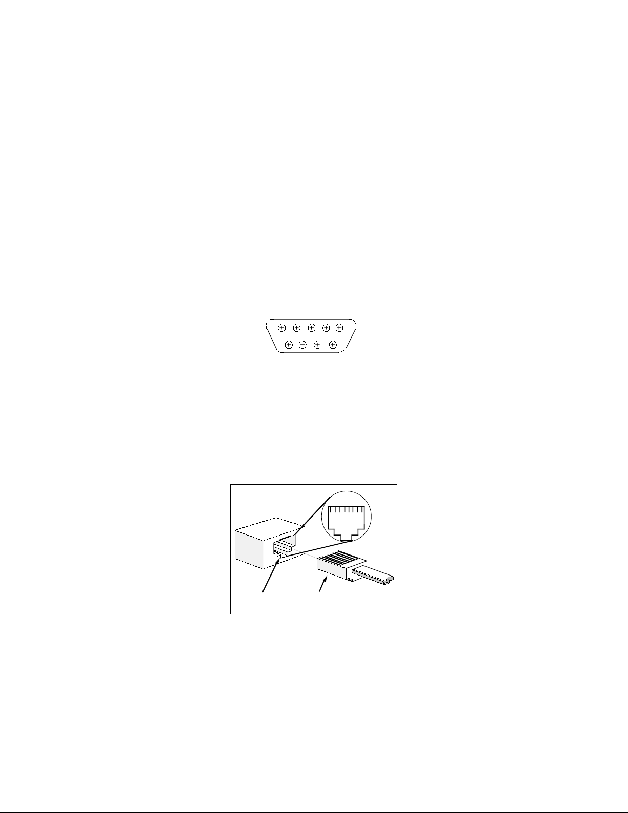
RJ-45 Port RJ-45 Connector
Figure 2. RJ-45 Connections
12345678
165
9
RJ-45 Interface
Type: RJ-45 port
Pin 1 No Connection Pin 5 Rx-
Pin 2 No Connection Pin 6 TX+
Pin 3 TX- Pin 7 No Connection
Pin 4 RX+ Pin 8 No Connection
Environmental Requirements
Operating Temperature:
0°to +60°C (32°to 140°F)
Operating Humidity:
10% to 90% (non-condensing)
Safety
DesignedinaccordancewithUL478,UL910,NEC725-
2(b), CSA, IEC, TUV, VDE class A. Meets FCC, Part
15, Class A limits.
WARNING:
It is the responsibility of the person who
sells the system of which the TRMF-2 will be a part to
ensure that the total system meets allowed limits of
conducted and radiated emissions.
Physical Properties
Dimensions:
3.26 L x 1.33 H inches
8.28 L x 3.36 H cm
INSTALLING THE TRMF-2
The installation of the TRMF-2 is a quick and simple
procedure. Before installing the TRMF-2, be sure you
havemeetalltherequirementslistedunderInstallation
Requirements and Specifications. Failure to do so
will result in improper operation of your network.
To install the TRMF-2:
1. Turn off the power for your PC.
2. Usingtheattachedcaptivemountingscrews,connect
theDB-9connector(1,Figure3)totheDB-9port(2,
Figure 3) on the adapter card.
3. Tighten the screws (3, Figure 3) to secure the
connector to the port.
4. Attach an RJ-45 connector (4, Figure 3) from the
UTP lobe link to the RJ-45 port (5, Figure 3) on the
TRMF-2.
5. Power up your PC.
The TRMF-2 is now ready for operation.