Cachelan SolarVu User manual

Fig 1 Typical connection for Acuvim II meter
TM
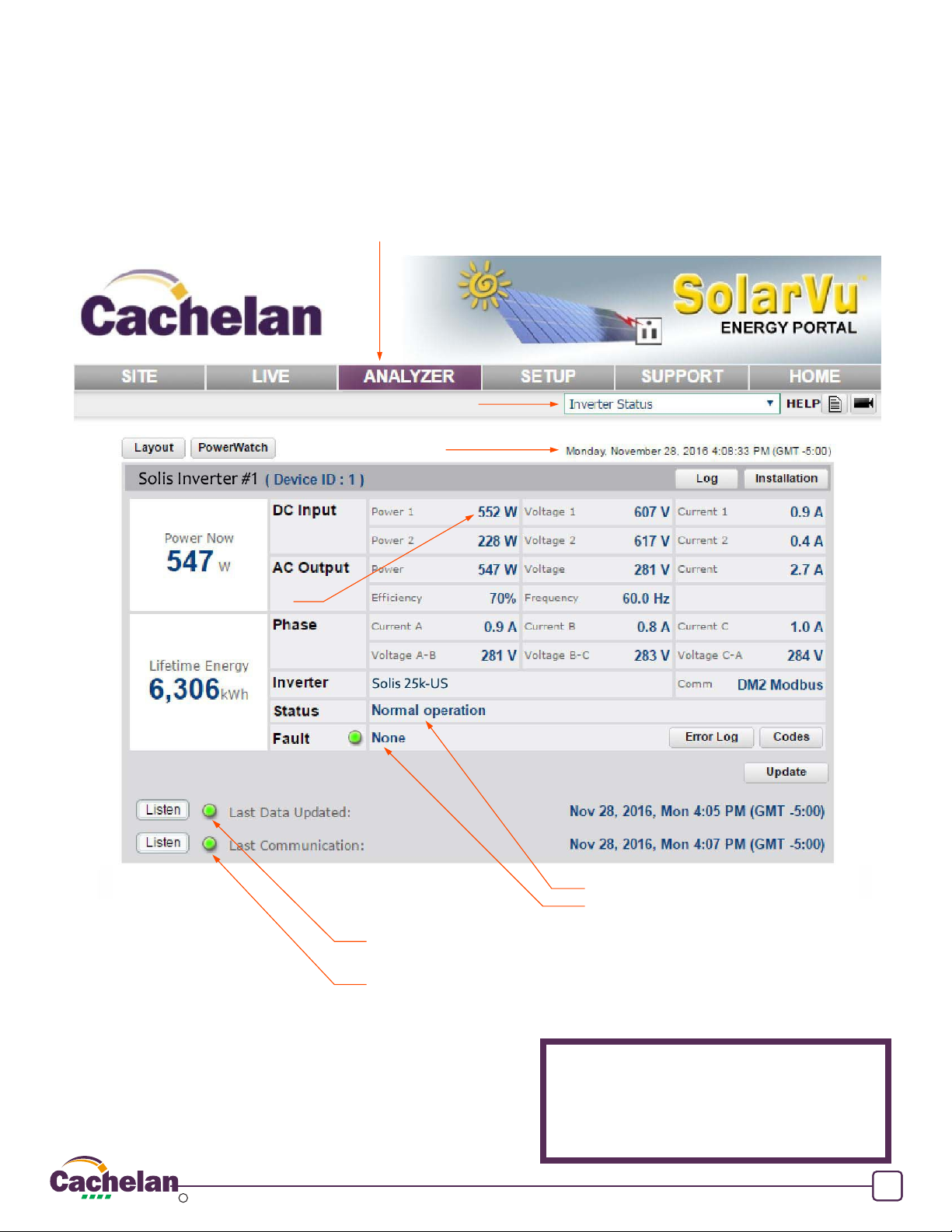
SolarVu is an energy portal that enables remote monitoring of renewable
energy generation sites over the internet. It requires the installation of a
SolarVu gateway which continuously transfers data from the inverters to the
remote SolarVu servers. This guide explains how to connect the M504
gateway to Solis Three Phase inverters. Several steps are required:
1) Connect the SolarVu gateway to the inverters
2) Connect the SolarVu gateway to the building LAN for internet access
3) Enter the communications settings into each inverter
4) Access SolarVu from a browser and configure the energy portal
Introduction
Site Preparation
1
®
SolarVu Installation Guide
For Solis Three Phase Inverters
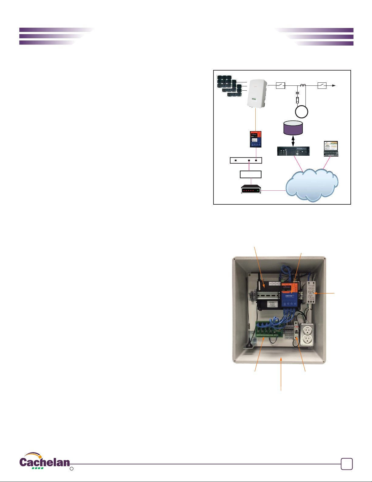
Fig 2 Typical SolarVu enclosure
M
To Grid
Utility Meter
FIREWALL
ROUTER
CORPORATE
ETHERNET LAN
CABLE/DSL
MODEM
Ethernet
Ethernet
INTERNET
SolarVu
SERVER
REMOTE BROWSER
ACCESS
ISP
DATABASE
RS485
To access SolarVu from a browser, the inverters communicate serially with a
SolarVu M504 gateway connected to the site network as shown in fig 1. The
M504 connects to inverter(s) over RS485 using shielded twisted pair wire,
daisy chained for multiple inverters. The LAN must have high speed internet
service to an ISP to provide access to the internet. The M504 RJ45 ethernet
jack plugs into an RJ45 LAN router or wall jack using a standard Cat5e patch
cable of convenient length. Alternatively, SolarVu can be ordered with a 3G
cellular modem for wireless internet connection. A 120VAC outlet for the
gateway power dongle is required.
SolarVu Gateway
(Datalogger)
3G Cellular Modem
or Optional Router
M504-485 terminal board.
Connect 485 Cat5e cable
to first inverter DM2 card
120VAC Breaker
24VDC
Power
supply
Drill holes and
attach conduit
M504 Gateway Installation
Power Supply: Connect from a 120VAC source to the breaker (terminal L),
terminal N and GND inside SolarVu enclosure as shown in fig 2.
RS485 Serial: Connect the RS485 serial Cat5e cable between the gateway
terminals and the Solis inverter’s RS485 terminal as shown in fig 3 and 4.
Being careful to match the inverter type and correct wire colour to the
terminals. Recommended cable type is Cat5e, 8 wire, UTP, #24 solid.
Twisted pair must be used for the RS485 serial data wires. Use a tie wrap to
provide strain relief for the Cat5e cable. Over 1000 feet of wire can be used
for reliable serial communications.
Ethernet: Use a standard ethernet patch cable with RJ45 plug on each end
of the appropriate length to connect from the RJ45 ethernet jack on the
gateway to the network ethernet at a RJ45 wall jack or router/switch. This is
usually an auto IP assignment using DHCP from a small sites but a larger
commercial organization my require static IP settings specified by the IT
system administrator. This should be specified at time of order. Settings as
shipped can be verified from the SolarVu configuration sheet included in the
enclosure document pouch. Alternatively, SolarVu can be ordered with a 3G
cellular modem/router installed for wireless connection. This requires
installation of a customer supplied SIM card with an active telco account for
service.
SMART GRID ENERGY 2018 Copyright CACHELAN cachelan.com SolarVu Installation Guide for Solis Three Phase Inverters IM1031-180306
c

2
1
Fig 3 Solis inverter RS485 terminal layout
Fig 4 Wiring one or several Solis Inverters
N Inverters
1 Inverter
Blue
Blue-White
1234
1D+ 1D- 1C 1G
P1
SolarVu M504-485 Terminal Board
* See drawing in
doc pouch for
port number P1-P4
Use twisted
pair
Inverter Communication Wiring
Blue
Blue-White
If there is only one inverter, connect the inverter’s RS485 terminal A-IN and B-IN contacts (1 and 2) to the SolarVu M504-485
Terminal Board’s D+ and D- contacts using a twisted pair. To connect more inverters, use another twisted pair to wire the A-
OUT and B-OUT (3 and 4) contacts of the connected inverter together with the A-IN and B-IN (1 and 2) contacts of the inverter
being added.
M504-485 D- Signal (blue-white wire)
M504-485 D+ Signal (blue wire)
ABA B
IN OUT
1 2 34
A B A B
IN OUT
1 2 34
MPPTs grid terminal
A B A B
IN OUT
1 2 34
MPPTs grid terminal
Solis inverter #1
Blue
Blue-White
1234
1D+ 1D- 1C 1G
P1
SolarVu M504-485 Terminal Board
* See drawing in
doc pouch for
port number P1-P4
Use twisted
pair
Blue
Blue-White
A B A B
IN OUT
1 2 34
MPPTs grid terminal
Solis inverter #1
Blue
Blue-White
1234
1D+ 1D- 1C 1G
P1
SolarVu M504-485 Terminal Board
* See drawing in
doc pouch for
port number P1-P4
Use twisted
pair
Blue
Blue-White
A B A B
IN OUT
1 2 34
MPPTs grid terminal
Solis inverter #1
Blue
Blue-White
1234
1D+ 1D- 1C 1G
P1
SolarVu M504-485 Terminal Board
* See drawing in
doc pouch for
port number P1-P4
Use twisted
pair
Blue
Blue-White
A B A B
IN OUT
1 2 34
MPPTs grid terminal
Solis inverter #1
Blue
ABA B
IN OUT
1 2 34
MPPTs grid terminal
Solis inverter #1
Blue-White
ABA B
IN OUT
1 2 34
MPPTs grid terminal
Solis inverter #2
Blue
Blue-White
A B A B
IN OUT
1 2 34
MPPTs grid terminal
Solis inverter #1
Blue
Blue-White
A B A B
IN OUT
1 2 34
MPPTs grid terminal
Solis inverter #N
Blue
Blue-White
...
SMART GRID ENERGY 2018 Copyright CACHELAN cachelan.com SolarVu Installation Guide for Solis Three Phase Inverters IM1031-180306
c

Inverter Configuration
Each Solis inverter must be configured with a unique Slave Address, which is also referred to as its ModBus address or ID. Required
inverter number settings are found in the SolarVu enclosure document pouch on the door and are normally assigned as 1,2,3... to
match the inverter number. Each Solis inverter must be powered on with a DC input to access the front panel display for entering
settings. Follow the following sequence for entering the settings for each inverter individually. It may be necessary to power cycle (off
then on) the inverter after making changes to ensure the inverter is using the newly assigned address ID.
On the initial interface, press the ‘ENTER’ key to view the menu.
Once the main menu is open, use the ‘DOWN’ key to select the ‘Settings’ tab,
then press the ‘ENTER’ key to open the sub-menu.
Within the ‘Settings’ sub-menu, use the ‘DOWN’ key to select the ‘Set
Address’ tab, then press the ‘ENTER’ key to open the ‘Set Address’ screen.
Refer to Cachelan communication SLD for detailed inverter address
assignment. Typically configure inverter address to match the inverter
number, i.e. inverter #1 has address 1, inverter #2 has address 2 and etc...
To enter the address, use the ‘UP’ and ‘DOWN’ keys to get to the required
address, then press the ‘ENTER’ key to submit the change.
3
Fig 5 Configuring Inverter Address
‘ESC’ Button
‘UP’ Button
‘DOWN’ Button
‘ENTER’ Button
SMART GRID ENERGY 2018 Copyright CACHELAN cachelan.com SolarVu Installation Guide for Solis Three Phase Inverters IM1031-180306
c

JUMPER SETTINGS
Terminator Resistor + Biasing
B+ B- T
ON
OFF
B+ Bias high = ON
B- Bias low = ON
504-485 Comm Board
T 120R termination = ON
PORT1 PORT2 PORT3 PORT4
485 serial communication ports
PayCheck is normally connected to
PORT 2.
See SLD drawing in doc pouch for
details
Blue data LED flashes when
transmitting and receiving
Power OFF-no power ON-power OK
Ready ON M504 booted up and running
Link/Act OFF-no ethernet connection
FLASH- data traffic activity
P1
P2
P3
P4
INDICATOR STATUS
LED NORMAL STATUS
IP Address Obtain IP by DHCP or set static IP
Network must be configured to same settings
Serial Check inverter connected to correct port.
Polarity of serial twisted pair wires.
Serial ID entered correctly in each inverter
Inverter Powered on.
Serial ID has been set to match SLD drawing.
Serial wiring correct.
Internet Internet connection for ISP to LAN working
Support For Cachelan technical support
905.470.8400 x224 [email protected]
TROUBLESHOOTING CHECKLIST
GE829
Serial Port 1 usually inverter
Transmit=orange, Receive=green, flashing
Serial Port 2 usually option
Transmit=orange, Receive=green, flashing
Serial Port 3 usually option
Transmit=orange, Receive=green, flashing
Serial Port 4 usually option
Transmit=orange, Receive=green, flashing
Fig 6 M504 Gateway Indicators
data from the inverter
GE828
ly connect to the internet through a browser then the network is already configured to accept the gateway. If a dedicated IP address was
programmed instead, subnet mask and DNS server address are required. This needs to be entered into the gateway before shipment.
Network configuration is shown on the gateway label and the Configuration Settings page in the doc pouch. Once the gateway receives
its IP address it acts as a client. It will automatically try to connect to the SolarVu server and begin transferring data from the inverter to
the server.
On power up, the gateway looks for a DHCP server to provide it a dynamic IP address. If a PC connected to the network can automatical-
Network Setup
4
SMART GRID ENERGY 2018 Copyright CACHELAN cachelan.com SolarVu Installation Guide for Solis Three Phase Inverters IM1031-180306
c

Testing the System
At this point the installation should be complete ready for testing. It is helpful to have access to a PC that is connected to the internet for
viewing SolarVu screens. Using the URL supplied for the system. The gateway is preconfigured to automatically send inverter data to
the SolarVu servers. To do this it must first establish an internet connection. Then it will collect data from the inverters and periodically
transmit it. Verifying correct operation is described in the sections that follow. Indicator lights and actual values accessible from the
SolarVu Analyzer > Inverter Status screen figure 6 are useful for determining the status of the system.
Fig 6 Use the ANALYZER > Inverter Status screen to check system status
Support
See the What is SolarVu? video at www.solarvu.net for a feature overview.
Each screen has a HELP button with details for the items on that view. A
printable HELP guide can be downloaded in SETUP > DOWNLOAD.
For additional technical support, send an email to [email protected]
or dial our support line in Toronto, Canada at 905.470.8400
Cachelan Technical Support
905.470.8400 x224
5
To access the inverter status screen, enter the SolarVu URL in your browser. Click ANALYZER
Inverter Status
Time of last update received
from SolarVu gateway
Measured values from the inverter
Faults reported by inverter
Status reported by inverter
Light is green if K135 is reading valid data from the inverter over RS485.
SolarVu gateway must be connected to the internet
Light goes green if SolarVu gateway to the internet
SMART GRID ENERGY 2018 Copyright CACHELAN cachelan.com SolarVu Installation Guide for Solis Three Phase Inverters IM1031-180306
c
Table of contents