1
1
3
4
5
2
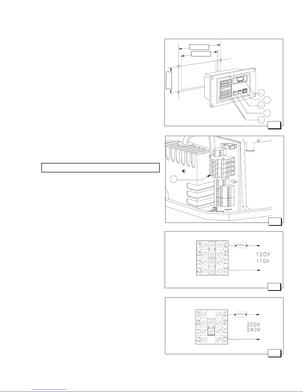
Fig.14
Fig.15
Fig.17
Fig.16
4.0. ELECTRICAL CONNECTIONS
4.1. Battery connection
To start the genset, an independent 12V battery, 18 - 30
capacity Ah min is needed.
It should be connected to the generator as shown in fig.
11 with cables up to 16'. For longer distances, follow the
sequence of operations described below:
- First connect the positive pole (+) of the battery to the
terminal marked with the symbol (+) on the generator,
(the starter).
- Then connect the negative pole (-) of the battery to the
terminal marked with the symbol (-) on the generator.
- Apply non-conductive grease to the connections to
protect against oxidation and corrosion.
- The generator has a built-in 10A charging circuit to
automatically recharge the start-up battery, giving
10 A, at a voltage of 12 V, when fully charged.
IMPORTANT
Install the battery in a well-ventilated area, away
from the generator and from any device which might
produce heat or sparks.
Periodically check the state of the connections of
the terminals and the water level of the battery. If the
cables need to be disconnected, follow the
instructions for connection in reverse order.
Do not invert the poles of the connecting cables
since serious damage might be caused to the
generator and the battery.
Do not connect other loads to the battery.
In order to minimize galvanic currents, the (-) of the
battery of the electric generator should not be connected
to the (-) of the other batteries on board.
4.2. Control panel connection
This connection can be made with the terminal strips (fig.
12, ref. 1) using the cables already connected to the
control panel. The terminals to be used are those marked
1 to 9 for the control cables. The ground should be
connected to the push-on terminal (fig. 12, ref. 3) insulating
them carefully and using a pre-insulated female push-on
connection. In making the connections it is important to
follow the diagram and the colours codes as indicate (fig.
13). Fasten the cable with the provided plastic support on
the bail (fig. 12, ref. 3).
The control panel contains 5 LEDs for operation and
alarm (fig. 14, ref. 1), an hour counter (fig. 14, ref. 2) and
the start and stop buttons (fig. 14, ref. 3/4/5).
For fixing the control panel is necessary to perforate as
shown in fig.14.
9
5-1/32"
4-3/4"
3-3/8"