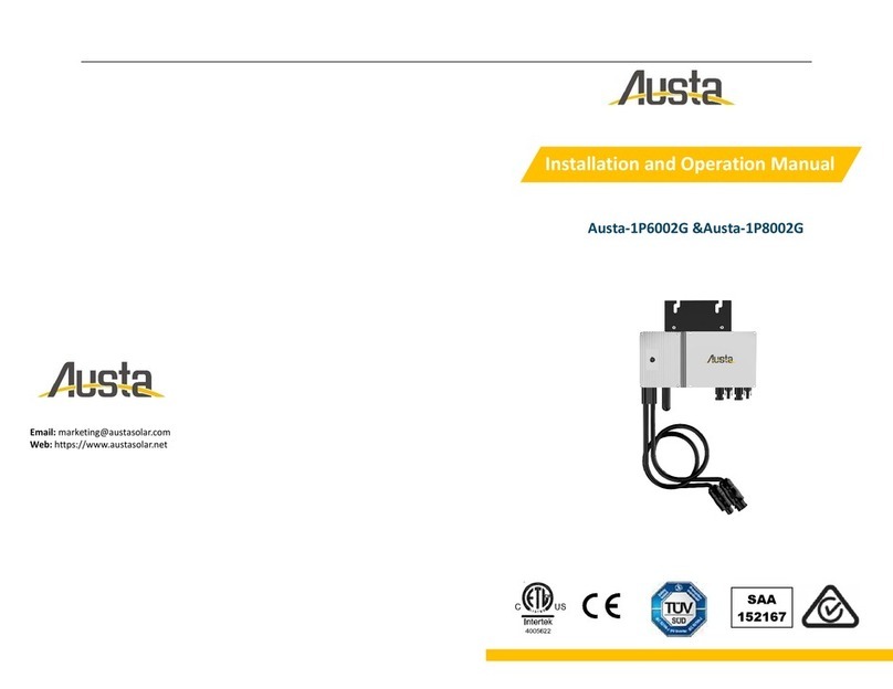
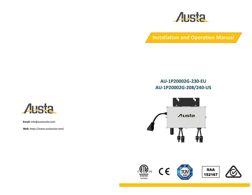
Austa AU-1P3002G User manual

AU-1P4002G
AU-1P3002G AU-1P3502G
AU-1P6002G
MICROINVERTER SYSTEM
MIKRO-WECHSELRICHTER SYSTEM
USER MANUAL
BENUTZERHANDBUCH
Scan Here for Austa App
Search "Austa Solar"
on Google Play and App Store
Android ios
NINGBO AUSTA SOLAR TECH CO.,LTD
www.austasolar.net
AU-1P8002G AU-1P10002G
AU-1P16002G AU-1P20002G

General Introduction
Austa Microinverter User Manual 1
This system is composed of a group of microinverters that convert direct current (DC) into alternating
current (AC) and feed the power to the public grid. The system is designed for one microinverter is
connected with one or two PV modules.
Each microinverter works independently so as to guarantee the maximum power generation of each
PV module. This setup is highly fexible and reliable as the system enables direct control of the
production of each PV module.
About the Manual
This manual contains important instructions for AU-1P300/350/400/600/800/1000/1600/20002G
microinverters, for security reasons, please install or debuge the equipment after reading the
instructions in this maual carefully.
Other Information
Product information is subject to change without notice.
User manual will be updated regularly, so please refer to Ausat offcial website at www.austasolar.net
for the latest version.

CONTENTS
Austa Microinverter User Manual 2
1. Important Notes
2.1 Important Safety Instructions
2.2 Explanation of Symbols
1.1 Product Range
1.2 Target Group
1.3 Symbols Used
1.4 Electromagnetic interference statement
2. Safety Instructions
3. Product Introduction
4.1
Position and Space Required
4.2 How to Connect PV Modules to Microinverter
4.3 Installation Tools
4.4 AC Branch Circuit Capacity
3.1 About PV Inverter System
3.2 About Microinverter
4. Installation Preparation
5. Microinverter Installation
6. Troubleshooting
6.1 Troubleshooting List
6.2 LED Indicator Status
7. Technical Data
3
3
3
3
3
4
4
5
6
6
6
7
7
7
7
8
9
12
12
12
13

1.Important Notes
1.1 Product Ranges
1.2 Target Group
1.3 Symbols Used
1.4 Electromagnetic interference statement
This manual describes the assembly, installation, debuging, maintenance and troubleshooting of the
following models of Austa Microinverter AU-1P300/350/400/600/800/1000/1600/20002G
Note:
‶600”means 600W output.
The safety symbols in this user manual are shown as below.
This indicates a hazardous situation that can result in deadly electric shocks, ot
her serious physical injuries, or fre incidents.
This indicates that directions must be strictly followed to avoid safety hazards
including equipment damage and personal injury.
This indicates that the act is forbidden. You should stop, use caution and fully
understand the operations explained before proceeding
This microinverter has been tested and complies with the requirements of CE EMC, meaning that it
will not be afected by electromagnetic interference. Please note that incorrect installation may cause
electromag-neticdisturbances.
You can turn the equipment of and on to see if radio or television reception is interfered by this
equipment. If this equipment does cause harmful interference to radio or television, please try the
following measures to fix the interference:
Austa Microinverter User Manual 3
Austa micro inverters are designed for residential use and it has feature of quick installation.
Users must read and follow the instructions in this manual to install the inverter, no professional
installers are required.
However, if the feed power exceeds the upper limit allowed by the state, it must be installed by
professional installers
We strongly recommend that children or people lacking relevant knowledge not attempt to operate
this system
1)Relocate other apparatus' antenna.
2) Move the microinverter farther away from the antenna.
3) Separate the microinverter and the antenna with metal/concrete materials or roof.
4) Contact your dealer or an experienced radio/TV technician for help.

Austa Microinverter User Manual 4
2.Safety Instructions
2.1 Important Safety Instructions
•
•
•
•
•
•
•
•
•
•
•
•
•
All operations including transportation, installation, start-up and maintenance must be carried outby
qualifed, trained personnel.
Check the product before installation to make sure there is no damage caused during transportation
because such damage can compromise the insulation integrity and safety clearances.
Choose installation location carefully and adhere to specifed cooling requirements. Unauthorized
removalof necessary protections, improper use, incorrect installation and operation may cause damage
to the equipment or incur serious safety and shock hazards.
You should get necessary approvals from local power operator before connecting the microinverter to the
power grid. This connection must be made only by qualifed technical personnel. It is the responsibility of
the installer to provide external disconnect switches and Over Current Protection Devices (OCPD).
Whenever the inverter has been disconnected from the public grid, please be extremely careful as some
components can retain charge sufcient to create a shock hazard. Before touching any part of the inverter,
please ensure the surface and the whole equipment are within the limit of safe temperature and voltage
potential.
Each input of the inverter is connected to one PV module. Do not connect batteries or other sources of
power supply. The inverter can be used only if all the technical parameters are observed and applied.
Do not install the equipment in flammable, explosive, corrosive, extremely hot/cold, and humid environm
-ent. Do not use the equipment when safety devices in these environments are not working.
Personal protective equipment such as gloves and goggles must be used during installation.
Inform the manufacturer about non-standard installation conditions.
Do not use the equipment if any operating anomalies are found.
Austa is not liable for any damage caused by incorrect or improper operation.
Electrical installation and maintenance shall be conducted by licensed electrician and shall comply with
local wiring rules
All repairs must be done with qualifed spare parts which must be installed in accordance with their inten
ded use and by a licensed contractor.
Liabilities arising from components that are not produced by Austa are on the part of their respective
manufacturers.
The AU-1P300/350/400/6002G microinverter is designed and tested according to international safety
require ments. However , certain safety precautions must be taken when installing and operating this
inverter. The installer must read and follow all instructions, cautions and warnings in this installation
manual.

Austa Microinverter User Manual 5
2.2 Explanation of Symbols
To comply with European Directive 2002/96/EC on Waste Electrical and Electronic
Equipment and its implementation as national law, electrical equipment that has
reached the end of its life must be collected separately and returned to an approved
recycling facility. Any device no longer needed must be returned to an authorized
dealer or approved collection and recycling facility.
Keep people out of 8 inches (20 cm) of the microinverter while it is operating.
Treatment
Caution
High voltage in the microinverter can cause dangers to life.
Danger of high voltage
The inverter can become hot during operation. Avoid contact with metal surfaces
during operation.
Beware of hot surface
The inverter complies with the Low Voltage Directive for the European Union &
2014/53/EU The Radio Equipment Directive (RED).
CE mark
Risk of electric shock,Energy storage timed discharge.
Caution
Please read the installation manual first before installation, operation and mainten-
ance.
Read manual first
2.Safety Instructions

3.Product Introduction
3.1 About PV Inverter System
3.2 About Microinverter
Screwdriver and wrenchDC Cable AC Cable/Schuko DC Connector-BC03
Wi-Fi Module
AC Connector-BC01
A typical grid-tied PV inverter system includes PV modules, PV inverter , and power grid , as shown be
low. PV inverter converts the DC power generated by PV modules into AC power that meets the requir
ements of the power grid. The AC power is then feed into the grid.
APV module
inverter
Power grid
B
C
Wi-Fi
App/Web
Microinverter
Note: See the bracket installation manual for more mounting accessories
Grid-tied PV system consists of PV panels, grid-tied inverter. The DC output from the PV panels is con
verted into AC energy and feedback tothe grid through the AU-1P300/350/400/6002G. AU-1P300/350/
400/6002G PV micro inverter contains isolation transformer with basic insulation between PV input
and AC grid output. This manual provides detailed product information and installation instructions
for the AU-1P600/8002G micro inverter. Please read through this manual before installation and
operation.
Austa Microinverter User Manual 6

4.Installation Preparation
4.1 Position and Space Required
4.2 How to Connect PV Modules to Microinverter
Please install the microinverter and all DC connections under the PV module to avoid direct sunlight,
rain exposure, snow buildup, UV etc. The silver side of the microinverter should be up and facing the
PV moduleLeave a minimum of 2 cm of front side the microinverter enclosure to ensure ventilation
and heat dissipation.
General Guidelines:
1. PV modules should be connected to DC input ports of a microinverter.
2. Use DC cable . Please consult the local power opera-tor to make sure that the DC cable complies
with local regulations.
The typical wiring method is shown below.
The voltage of modules (considering the effect of local temperature) must not exceed the maximum
input voltage of the microinverter. Otherwise, the microinverter maybe damaged.
(refer to theTechnical Data section to determine the absolute maximum input voltage).
Note:
4.3 AC Branch Circuit Capacity
Note:
1. Microinverters can be connected to the same AC branch, as long as the total currentdoes not exceed
the ampacity specifed in local regulations.
The Austa AU-1P300/350/400/600/800/1000/1600/20002G can be paralleled using the paralleling
interface on the microinverter. The number of microinverters on the AC branch must not exceed the
limits. Do not exceed the maximum number of microinverters in the AC branch circuit, as indicated on
the unit rating label. For 12AWG trunk cables, each microinverter's AC branch circuit must come from
a dedicated branch circuit protected by a 20A maximum circuit breaker.
The Austa microinverter system is designed to connnect max four PV modules.
AU-1P300/350/4002G can connect one PV module. AU-1P600/8002G can connect two PV modules.
AU-1P1000/1600/20002G can connect four PV modules.
The inverter can support over matching 1.5 times, such as AU-1P6002G can connect max 900W PV
modules input.
Austa Microinverter User Manual 7

4.Installation Preparation
4.4 Precautions
The equipment is installed based on the system design and the location .
2. Ensure that protective end caps are installed on all unused AC connectors. Unused AC harness
connectors are energised when the system is powered up.
3. AU-1P300/350/4002G supports up to maximum 11 units branch. AU-1P6002G supports up to
maximum 6 units branch. AU-1P8002G supports up to maximum 5 units branch. AU-1P10002G
supports up to maximum 3 units branch. AU -1P1600/20002G supports up to maximum 2units branch.
•
•
•
•
•
•
•
•
The installation must be done with the equipment disconnected from the grid (power disconnect
switch open) and with the PV modules shaded or isolated.
Make sure the environmental conditions of the microinverter’s requirement (degree of protection,tem
perature, humidity, altitude, etc.) as specifed in the Technical Data section.
Avoid direct sunlight to prevent power derating which can be caused by an increase in the internal
temperature of the micro inverter.
Keep the inverter in well-ventilated place to avoid over heating.
Keep the inverter away from gases or fammable substances.
Avoid electromagnetic interference because it can compromise the normal operation of electronic
equipment.
Install only on structures specifcally designed for PV modules (supplied by installation technicians).
Install microinverter underneath PV modules to make sure it works in the shadow. Nonobservance
may cause the derating of inverter production.
Installation location shall meet the following conditions:
Austa Microinverter User Manual 8

Note:
The voltage of modules (considering the effect of local temperature) must not exceed the maximum
input voltage of the microinverter. Otherwise, the microinverter maybe damaged (refer to the
Technical Data section to determine the absolute maximum input voltage).
5.Microinverter Installation
Step 1. Plan and Install the Microinverter
Step 2. Connect PV Modules
Note:
1.Microinverter installation and DC connections must be done under the PV module to avoid direct
sunlight,rain exposure, snow buildup, UV etc.
2.Leave a minimum of 2 cm of space around the microinverter enclosure to ensure ventilation and
heat dissipation.
Note:
1. Make sure that the AC Connectors are kept away from any drainage channels.
2. In case you need to remove the microinverter AC cable from interface, Removal is accomplished by
inserting an MC4 spanner into the side connector.
3. The order of Step 1 and Step 2 can be reversed according to your planned needs.
Before you install, you should have the following devices:
MicroInverter
Required photovoltaic modules
Mounting brackets according to your installation design
AC cable and solar cables that meet your requirements in length
Suitable installation tools and no less than 2 people
A) Mount the PV modules above the microinverter.
B) Connect the PV modules’ DC cables to the DC input side of the microinverter. Wait five minutes
and you'll see the LED will turn red and flashing.
A B C
PV module DC cable Microinverter
Austa Microinverter User Manual 9
1
2
3
+
-
+
-
+
-
+
-

5.Microinverter Installation
Austa Microinverter User Manual 10
Step 3. Connect the inverter to the monitoring App
Before starting this operation, please ensure that you already have the following conditions
1. 2.4Ghz Wi-Fi network is available
2. Make sure you know the access password of this Wi-Fi network
3. You have a inverter without defective
4. You have correctly downloaded the latest version of the Austa App
Click“Wi-Fi Configuration”
ready to enter
Your microinverter is
configurated successfully!
Select your home Wi-Fi
Click“Setup Wi-Fi connection”
Access the Home Wireless Click to select
home Wi-Fi
Android ios
01
02 03
07
Download and Install "Austa Solar" App
Please wait for 90 secs
Click to“Connect to the
Device's WiFi”
04
Connect the inverter
network MI-xxxxxxxx
05
08
Note: Microinverter support 2.4Ghz Wi-Fi only
Click the blue
test button,
and click the
setting
06

Austa Microinverter User Manual 11
5.Microinverter Installation
APP Registertion
Click the Register option
How to disconnect inverter from PV Module safely
To ensure the inverter is not disconnected from the PV modules under load,adhere to the following
disconnection steps in the order shown:
1. Disconnect the AC by opening the branch circuit breaker.
2. Disconnect the first AC connect or in the branch circuit.
3. Cover the module with an opaque cover.
4. Using a DC current probe verify there is no current flowing in the DC wires between the PV module
and the AU-1P300/400/600/800/1000/1600/20002G.
5. Care should be taken when measuring DC currents,most clamp-on meters must be zeroed first and
tend to drift with time.
6. Disconnect the PV module DC wire connectors from the AU-1P300/400/600/800/1000/1600/20002G.
7. Remove the AU-1P300/400/600/800/1000/1600/20002G from the PV array racking
Note: Only operate when AC grid is connected
Connecting the AC port to the power grid,after LED flashes GREEN every 3 secs, then configuration is
done.Be careful to connect the AC cable to the inverter first.If the green light does not come on, it
means that the configuration is wrong, please unplug the AC terminal from the grid connection and
the DC port connection, and let it stand for 1 minute to reopen the network operation.
+
-
+
-
2
1
1
2
09
Use AUSTA APP
and register your ID with
your avaliable information
Note that '*'is a required field
Add inverter
10
11
Inverter adding sucessful
Press the inverter list
12
you can check
Status for each
inverters
Step 4. Add inverter in APP

6.Troubleshooting
6.1 Troubleshooting List
6.2 LED Indicator Status
In case of fault, Austa inverter has multiple protective functions and stops output power. The fault m
essage may be sent to a connected gateway through power line communication.
1. Do not attempt to repair the microinverter; the microinverter contains no user-serviceable parts. If
troubleshooting methods fail, return the microinverter to your dealer for repair.
2. Never disconnect the DC lead connector under load. Make sure there is no current in the DC leads
before disconnecting. Before disconnecting, the module can be covered with thermal insulation.
3. The product is powered by the DC power supply of the PV module. Make sure you disconnect the D
C power supply Make sure you disconnect the DC power supply and reconnect the DC power supply
to observe the LEDs come on for two seconds and the LEDs go off for two seconds after the DC power
supply is turned on.
4. Always disconnect AC power before disconnecting PV module wiring from the microinverter.Micro-
inverter AC Once the AC branch circuit breaker at the load centre has been opened, the AC connector
of the first microinverter in the branch circuit serves as the means of disconnection.
The micro inverter is powered on when sufficient DC voltage from the module is applied. The status
LED will start flashing after sufficient DC power is applied as an indication that the micro inverter is
live.
The“ LED indicator”is placed at the bottom
Do not attempt to repar the microinverter yourself. If the troubleshooting fails, please return it to
the dealer for replacement.
Note:
The microinverter is powered by DC side. If the LED light is not on,please check the DC side connec-
tion. If the connection and input voltage are normal, contact your dealer or Austa technical support
team.
LED
Status Meaning
LED turn Green and Flashing every 2 seconds
LED turn Red and Flashing every 2 seconds
LED trurn Orange and Flashing every 2 seconds
LED turn Green and Flashing every seconds
LED turn and keep Red color
LED turn Orange and Flashing every seconds
Standby
Standby
Standby
Error
Wireless connection -Error
Producing
Producing
Producing
Normal
Grounding Fault
Wireless connection -Error
Normal
Austa Microinverter User Manual 12

7.Technical Data
Verify that the voltage and current specifcations of the PV module match those of the microinverter.
The maximum open circuit voltage rating of the PV module must be within the operating voltage
range of the microinverter.We recommend that the maximum current rating at MPPT should be equal
to or less than the maximum input DC current.
Recommended PV Module Power Range / W 300~450
33-55
24
14
18
II
350
350300
230
Configurable
1.3
2.2 4.4
2.5
50 / Configurable
50 / Configurable 50 / Configurable
<3%
III
-40~65
0-100%
180 x 186 x 25
1.5
MC4 MC4
MC4
Daisy Chain AC Bus
PLC or WiFi
IP-66 /67
97.1%
>99.5%
>0.99 >0.99 >0.99
80 80 80
>99.5% >99.5%
97.3% 96.9%
IP-66 /67 IP-66 /67
PLC or WiFi PLC or WiFi
Daisy Chain AC Bus Daisy Chain AC Bus
1.9 2.9
180 x 186 x 25 277x 132x 50
0-100% 0-100%
-40~65 -40~65
III III
<3%<3%
1.52 2.5
Configurable Configurable
230 230
400 600
600
II II
18
16
60 60
24 24
33-55 22-55
400~600
350
2.5
50 / Configurable
MC4
>0.99
80
>99.5%
97.3%
IP-66 /67
PLC or WiFi
Daisy Chain AC Bus
1.9
180 x 186 x 25
0-100%
-40~65
III
<3%
1.5
Configurable
230
350
II
18
16
60
24
33-55
350~525 (300~450)x2
14x2
18x2
Input | DC
MPPT Voltage Range / V
Startup Voltage / V
Max. Input Voltage / V
Max. Input Current / A
Max. DC Short Circuit Current/A
DC Overvoltage Protection Category
Peak Output Power / VA
Max. Continous Output Power / VA
Rated Output Voltage / V
Nominal Output Voltage Range / V
Max. Continous Output Current / A
Nominal Frequency / Range / Hz
Power Factor (Nominal/Adjustable Range)
AC Short Circuit Fault Current
THDi@Rated Power
AC Overvoltage Protection Category
Operating Ambient Temperature Range / ℃
Relative Humidity Range
Dimensions (W x H x D) / mm
Weight / kg
DC Connector Type
AC Connection Type (inverter-inverter)
Communication Method
Protection Class
Peak Efficiency
MPPT Efficiency
Night Power Consumption / mW
AU-1P3002G AU-1P3502G AU-1P4002G AU-1P6002G
Austa Microinverter User Manual 13
60

7.Technical Data
Recommended PV Module Power Range / W (400~600)x 2
17x 2
20x 2 20x 2
17x 2 20x 4
25x 4 25x 4
20x 4
22-55
24
80
800
II II II II
230
Configurable
3.48
9.6A 9.6A 18A 18A
50 / 60 50 / 60 50 / 60 50 / 60
<3%
III
-40~65
0-100%
268 x 250 x 42 268 x 250 x 42
2.9
MC4 MC4MC4
Daisy Chain AC Bus
PLC or WiFi
97.1%
>99.5%
>0.99 >0.99 >0.99
10 years 10 years 10 years
>99.5% >99.5%
97.1% 97.1%
PLC or WiFi PLC or WiFi
Daisy Chain AC Bus Daisy Chain AC Bus
2.9 5.33
0-100% 0-100%
-40~65 -40~65
III III
<3%<3%
4.34 9.62
Configurable Configurable
230 230
1000 2000
80 80
6060 60
24 24
22-55 22-55
(500~750)2 (500~700)x 4
MPPT Voltage Range / V
Startup Voltage / V
Max. Input Voltage / V
Max. Input Current / A
Max. DC Short Circuit Current/A
Night Power Consumption / mW
Rated Output Power /W
DC Overvoltage Protection Category
Rated Output Voltage / V
Nominal Output Voltage Range / V
Max. Continous Output Current / A
Nominal Frequency / Range / Hz
Power Factor (Nominal/Adjustable Range)
Max. AC Fault Current
THDi@Rated Power
AC Overvoltage Protection Category
Operating Ambient Temperature Range / ℃
Relative Humidity Range
Dimensions (W x H x D) / mm
Weight / kg
DC Connector Type
AC Connection Type (inverter-inverter)
Communication Method
Protection Class
Peak Efficiency
MPPT Efficiency
Warranty
AU-1P8002G AU-1P10002G AU-1P16002G
MC4
>0.99
10 years
>99.5%
97.1%
PLC or WiFi
Daisy Chain AC Bus
5.33
300 x 233 x 38 300 x 233 x 38
0-100%
-40~65
III
<3%
6.52
Configurable
230
1600
80
60
24
22-55
(400~600)x4
AU-1P20002G
Austa Microinverter User Manual 14
IP-66 /67 IP-66 /67 IP-66 /67 IP-66 /67

Austa Mikrowechselrichter 15
Allgemeine Einführung
Dieses System besteht aus einer Gruppe von Mikro-Wechselrichtern, die Gleichstrom (DC) in
Wechselstrom (AC) umwandeln und den Strom in das öffentliche Netz einspeisen. Das System ist für
einen Mikro-Wechselrichter ausgelegt, der mit einem oder zwei PV-Modulen verbunden ist.
Jeder Mikro-Wechselrichter arbeitet unabhängig, um die maximale Stromerzeugung jedes PV-Moduls
zu gewährleisten. Dieser Aufbau ist äußerst flexibel und zuverlässig, da das System eine direkte
Steuerung der Produktion jedes PV-Moduls ermöglicht.
Über das Handbuch
Dieses Handbuch enthält wichtige Anweisungen für AU-1P300/350/400/600/800/1000/1600/20002G
Aus Sicherheitsgründen sollten Sie das Gerät erst installieren oder testen, nachdem Sie die Anweis-
ungen in diesem Handbuch sorgfältig gelesen haben.
Andere Informationen
Die Produktinformationen können ohne vorherige Ankündigung geändert werden.
Das Benutzerhandbuch wird regelmäßig aktualisiert, daher finden Sie die neueste Version auf der
offiziellen Austa-Website unter www.austasolar.net.

INHALT
Austa Mikrowechselrichter 16
1. Wichtige Hinweise
2.1 Wichtige Sicherheitshinweise
2.2 Erläuterung von Symbolen
1.1 Produktpalette
1.2 Zielgruppe
1.3 Verwendete Symbole
1.4 Erklärung zu elektromagnetischen Störungen
2. Sicherheitshinweise
3. Produkt-Einführung
4.1
Position und Platzbedarf
4.2 Anschluss von PV-Modulen an Mikro-Wechselrichterr
4.3 Installationswerkzeuge
4.4 Kapazität des AC-Zweigstromkreises
3.1 Über das PV-Wechselrichtersystem
3.2 Über Microinverter
4. Vorbereitung der Installation
5. Mikro-Wechselrichter-Installation
6. Fehlersuche
6.1 Fehlersuchliste
6.2 LED-Anzeige Status
7. Technische Daten
17
17
17
17
17
18
18
19
20
20
20
21
21
21
21
22
23
26
26
26
27

1.Wichtige Hinweise
1.1 Produktpaletten
1.2 Zielgruppe
1.3 Verwendete Symbole
1.4 Erklärung zu elektromagnetischen Störungen
Anmerkung:
‶600”bedeutet 600 W Leistung.
Die Sicherheitssymbole in diesem Benutzerhandbuch sind wie folgt dargestellt.
Dies weist auf eine gefährliche Situation hin, die zu tödlichen Stromschlägen,
anderen schweren Körperverletzungen oder Brandfällen führen kann.
Dies bedeutet, dass die Anweisungen strikt befolgt werden müssen,
um Sicherheitsrisiken, wie z. B. Schäden am Gerät und Verletzungen,
zu vermeiden.
Dies bedeutet, dass die Handlung verboten ist. Halten Sie an, seien Sie vorsichtig
und machen Sie sich mit den erklärten Vorgängen vertraut, bevor Sie fortfahren.
Dieser Mikrowechselrichter wurde geprüft und erfüllt die Anforderungen der CE-EMV, was bedeutet,
dass er nicht durch elektromagnetische Störungen beeinträchtigt wird. Bitte beachten Sie, dass eine
falsche Installation elektromagnetische Störungen verursachen kann.
Sie können das Gerät aus- und einschalten, um zu sehen, ob der Radio- oder Fernsehempfang durch
dieses Gerät gestört wird. Wenn dieses Gerät Störungen beim Radio- oder Fernsehempfang
verursacht, versuchen Sie bitte, die folgenden Maßnahmen zu ergreifen, um die Störungen zu
beheben:
Austa Mikrowechselrichter 17
Die Austa-Mikro-Wechselrichter sind für den privaten Gebrauch konzipiert und zeichnen sich durch
eine schnelle Installation aus.
Der Benutzer muss die Anweisungen in diesem Handbuch lesen und befolgen, um den Wechselrichter
zu installieren; ein professioneller Installateur ist nicht erforderlich.
Übersteigt die Einspeiseleistung jedoch die staatlich zugelassene Obergrenze, muss die Installation
von professionelle Installateure installiert werden.
Wir empfehlen dringend, dass Kinder oder Personen ohne einschlägiges Wissen nicht versuchen,
dieses System zu bedienen
1)Versetzen Sie die Antenne eines anderen Geräts.
2) Stellen Sie den Mikro-Wechselrichter weiter von der Antenne entfernt auf.
3) Trennen Sie den Mikro-Wechselrichter und die Antenne durch Metall/Beton oder ein Dach.
4) Wenden Sie sich an Ihren Händler oder einen erfahrenen Radio-/Fernsehtechniker, um Hilfe zu erhalten.
Dieses Handbuch beschreibt die Montage, Installation, Fehlersuche, Wartung und Fehlerbehebung
der folgenden Modelle der Austa Microinverter AU-1P300/350/400/600/800/1000/1600/20002G

Austa Mikrowechselrichter 18
2.Sicherheitstechnische Hinweise
2.1 Wichtige Sicherheitshinweise
•
•
•
•
•
•
•
•
•
•
•
Der Mikro-Wechselrichter AU-1P300/350/400/6002G wurde gemäß den internationalen Sicherheitsan-
forderungen entwickelt und getestet. Dennoch müssen bei der Installation und dem Betrieb dieses
Wechselrichters bestimmte Sicherheitsvorkehrungen getroffen werden. Der Installateur muss alle
Anweisungen, Vorsichtshinweise und Warnungen in diesem Installationshandbuch lesen und
befolgen.
Alle Arbeiten, einschließlich Transport, Installation, Inbetriebnahme und Wartung, müssen von qualifizier-
tem und geschultem Personal durchgeführt werden.
Vor dem Anschluss des Mikro-Wechselrichters an das Stromnetz sollten Sie die erforderlichen
Genehmigungen des örtlichen Stromversorgers einholen. Dieser Anschluss darf nur von qualifiziertem
Fachpersonal vorgenommen werden. Es liegt in der Verantwortung des Installateurs, externe Trennschal-
ter und Überstromschutzvorrichtungen (OCPD) bereitzustellen.
Jeder Eingang des Wechselrichters ist mit einem PV-Modul verbunden. Schließen Sie keine Batterien oder
andere Stromversorgungsquellen an. Der Wechselrichter kann nur verwendet werden, wenn alle
technischen Parameter eingehalten und angewendet werden.
Installieren Sie das Gerät nicht in entflammbaren, explosiven, ätzenden, extrem heißen/kalten und
feuchten Umgebungen. Verwenden Sie das Gerät nicht, wenn die Sicherheitsvorrichtungen in diesen
Umgebungen nicht funktionieren.
Bei der Installation ist eine persönliche Schutzausrüstung wie Handschuhe und Schutzbrille zu tragen.
Informieren Sie den Hersteller über nicht normgerechte Einbaubedingungen.
Verwenden Sie das Gerät nicht, wenn Sie Anomalien im Betrieb feststellen.
Alle Reparaturen müssen mit qualifizierten Ersatzteilen durchgeführt werden, die entsprechend ihrem
Verwendungszweck und von einem zugelassenen Fachmann eingebaut werden müssen.
Haftung für Komponenten, die nicht von Austa produziert werden, liegt bei den jeweiligen Herstellern.
Wenn der Wechselrichter vom öffentlichen Stromnetz getrennt wurde, seien Sie bitte äußerst vorsichtig,
da einige Komponenten eine ausreichende Ladung behalten können, um eine Stromschlaggefahr
darzustellen. Bevor Sie einen Teil des Wechselrichters berühren, vergewissern Sie sich bitte, dass die
Oberfläche und das gesamte Gerät innerhalb der sicheren Temperatur- und Spannungsgrenzen liegen.
Überprüfen Sie das Produkt vor der Installation, um sicherzustellen, dass es keine Transportschäden
aufweist, da solche Schäden die Integrität der Isolierung und die Sicherheitsabstände beeinträchtigen
können.
Wählen Sie den Aufstellungsort sorgfältig aus und halten Sie die vorgeschriebenen Kühlungsanforderun-
gen ein. Unerlaubtes Entfernen notwendiger Schutzvorrichtungen, die unsachgemäße Verwendung, die
falsche Installation und der falsche Betrieb können zu Schäden am Gerät oder zu ernsthaften Sicherheits-
und Stromschlaggefahren führen.

Austa Mikrowechselrichter 19
2.Sicherheitstechnische Hinweise
•
•
2.2 Erläuterung von Symbolen
Austa haftet nicht für Schäden, die durch falsche oder unsachgemäße Bedienung entstehen.
Die Elektroinstallation und -wartung muss von einem lizenzierten Elektriker durchgeführt werden und
den örtlichen Verdrahtungsvorschriften entsprechen.
Behandlung
Vorsicht
Gefahr durch Hochspannung
Gemäß der europäischen Richtlinie 2002/96/EG über Elektro- und Elektronik-Alt-
geräte und ihrer Umsetzung in nationales Recht müssen Elektrogeräte, die das Ende
ihrer Lebensdauer erreicht haben, getrennt gesammelt und einer zugelassenen
Recyclinganlage zugeführt werden. Jedes nicht mehr benötigte Gerät muss bei
einem autorisierten Händler oder einer zugelassenen Sammel- und Recyclingstelle
abgegeben werden.
Halten Sie Personen während des Betriebs vom Mikrowechselrichter fern (20 cm).
Eine hohe Spannung im Mikrowechselrichter kann lebensgefährlich sein.
Vorsicht
Gefahr eines elektrischen Schlages, Energiespeicher mit zeitlicher Entladung.
Lesen Sie zuerst das Handbuch
Bitte lesen Sie vor der Installation, dem Betrieb und der Wartung zuerst die
Installationsanleitung.
CE-Kennzeichnung
Der Wechselrichter entspricht der Niederspannungsrichtlinie für die Europäische
Union &2014/53/EU The Radio Equipment Directive (RED).
Vorsicht vor heißer Oberfläche
Der Wechselrichter kann während des Betriebs heiß werden. Vermeiden Sie während
des Betriebs den Kontakt mit Metalloberflächen.
This manual suits for next models
7
Table of contents
Languages:
Other Austa Inverter manuals
Popular Inverter manuals by other brands

Mitsubishi Electric
Mitsubishi Electric FR-A700 Series INSTALLATION GUIDELINE
Agilent Technologies
Agilent Technologies AGILENT U2761A user guide
SycoTec
SycoTec easyDrive 4330 IP00 operating manual

Omron
Omron SYSDRIVE 3G3HV SERIES user manual
PNI
PNI GreenHouse SC1800B user manual
DieHard
DieHard 200.71495 owner's manual
Carrier
Carrier 38QUS014D8S2-1 Service manual

Mitsubishi Electric
Mitsubishi Electric FR-D700 Series instruction manual
SMA
SMA SB3000TL-US-22 Assembly

Telwin
Telwin CONVERTER 300 Instuction manual
Extel
Extel UNIVERSAL 15 Installation and user guide
Grid Tie
Grid Tie PV-5000T-U Installation & operation manual
