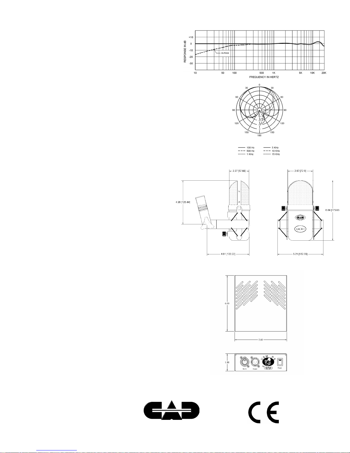
manuals.online logo
Brands
  1. Home
  2. •
  3. Brands
  4. •
  5. CAD
  6. •
  7. Microphone
  8. •
  9. CAD VSM User manual

CAD VSM User manual

The VSM is a cardioid single tube true
condenser microphone that features servo-
valve technology and the exclusive CAD
Optema OS 110 capsule. The VSM is a natu-
ral bridge between the valve technology
developed for the VX2 microphone and the
servo opamp technology developed for the
Equitek series microphones. The head amp
in the VSM microphone is a 12AX7 tube in a
circuit that is optimized for maximum headroom
and low noise. The output stage is a high
speed dual opamp in a balanced differential
configuration that allows long cables to be
used without affecting microphone perfor-
mance.
 True large diameter capsule with 1.1" inside diameter. (1.34" out-
side diameter.)
 3 Micron thick high tension, diaphragms made from the latest
high strength polymer film.
 24K Gold sputtered diaphragm coating.
 Each capsule is hand adjusted for proper damping and consistent
frequency response.
 Other capsule components made from precision machined brass
and stainless steel.
The VSM has extremely wide frequency
response and dynamic range with a slight
rising response characteristic at 15KHz. The
VSM is ideal for both vocal and instrument
recording applications. The VSM comes
complete with an elastic suspension mount,
heavy duty analog power supply, and a 30
foot professional 7 conductor cable.
Optema Series,
OS 110 Condenser
Capsule
The VSM comes with an OS 110 series capsule that is manufac-
tured in our capsule facility in Conneaut, Ohio. The OS 110 capsule
features:
VSM Shock Mount
The VSM shock mount is an integral part of the VSM micro-
phone and only needs to be removed to service the microphone. To
remove the shock mount, unscrew the two knurled knobs on either
side of the microphone and the knurled knob in the back of the micro-
phone.
Use and Operation
Mount the microphone in the desired location. Plug the included
seven pin cable into the microphone and the power supply. The out-
put of the microphone is at the 3 pin XLR connector on the power
supply. Use a standard balanced 3 pin XLR cable to connect the
microphone output to the input of your mixer or recorder. Phantom
power is not required. Plug the power supply into your AC mains
supply. Turn the power supply on using the rocker switch on the right
side of the front panel of the power supply. The LED on the rocker
switch will light. Allow a few minutes for the vacuum tube in the micro-
phone to warm-up and stabilize. The output level of the VSM is quite
high. It is recommended that you start with trim control or input level
control turned down on your mixer or recorder. It is also recommended
that you turn down your input level whenever changing any of the
switch settings on the microphone.
Large Diaphragm
Condenser Tube
Microphone
Pad Off
(0 dB)
Flat
Response
High-Pass
On
-8 dB Pad
Engaged
-16 dB Pad
Engaged
This Microphone Demands Respect!!*
* For the potentially lethal voltages inside the micro-
phone and power supply during operation. Never
open the microphone housing when it is connected
to the power supply. The power supply has no user
serviceable parts inside. The power supply should
only be opened by a qualified service technician.
VSM Switch Functions
Power Supply
The VSM power supply is set for 117VAC opera-
tion at the factory. (For units sold in the U.S.A.) For
220VAC operation, change the switch on the rear panel
of the supply to 220V.
Tube Replacement
The tube used in the VSM has been hand selected for
low noise, and burned in to provide years of service. The
tube used in the VSM is 12AX7 type. The actual number that
appears on the tube in your microphone may be different.
This tube is a very popular type used in a variety music and
recording related products. However, to insure continued op-
eration within factory specs, it is recommended that you
purchase replacement tubes from CAD. Contact the CAD Cus-
tomer Service Department at 1-888-702-7075.
To gain access to the tube, first disconnect the micro-
phone from its power supply. Remove the microphone from
the shock mount by unscrewing the two knurled knobs on
either side of the microphone head. Then unscrew the single
knurled knob on the back of the mic near the XLR connector.
Remove the switch bezel by removing the screws on the sides
of the bezel. Remove the mic housing by unscrewing the two
screws on the end of the mic near the XLR connector. Care-
fully slide the housing off, making sure the housing clears the
small toggle switches.
Remove the tube through the opening in the microphone
chassis. Make sure that the replacement tube is seated firmly
in the socket.
Replace the body by sliding it over the chassis, being
careful to clear the toggle switches. Center the body over the
XLR connector at the end of the chassis. Replace the screws
in the end of the housing. Replace the switch bezel and the
switch bezel screws. Note: If the screws in the switch bezel
do not align properly, the body may not be fully seated. Loosen
the screws on the body and realign it first. Replace the micro-
phone in the shock mount.
Care and Maintenance
The VSM should be kept in clean dry environ-
ment, free from temperature extremes. If the housing
becomes soiled, it can be cleaned with a cloth moist-
ened in isopropyl alcohol.
Fuse
The fuse holder for the VSM power supply is located on
the rear panel. The fuse is a 5mm X 20mm size, .160 A. Slow
Blow, @ 250V. In the event that the fuse needs to be re-
placed, make sure to select a replacement fuse of equal rating.
VSM Power Supply
For most applications, the pad switch should be
left in the 0dB position, and the Hi-Pass switch should
be in the flat position. When miking loud sources such
as drums and amplified instruments, the pad switch
may be needed. If audible clipping occurs, first try
adjusting the input pad or trim control on your mixer.
If this has no effect, then engage either the -8 dB or
-16 dB pad on the microphone. The HI-Pass filter
can be engaged when it is desired to reduce low
frequency levels.
VSM Specifications
Type:
Side address, true condenser.
Capsule:
Optema OS 110 series, 1.1" inside diameter, gold sputtered.
Frequency Response:
10Hz - 20 kHz.
Polar Pattern:
Cardioid.
Impedance:
Low (200 ohms nominal).
Output Level At 1 kHz.:
Open Circuit Voltage:
-53 dB (0 dB = 1 volt per microbar).
22.4 mV/Pascal.
Dynamic Range:
118 dB (Noise floor to max SPL @ less than 0.5% THD).
119.5 dB (Noise floor to max SPL @ less than 5.0% THD).
Equivalent Noise Level:
15 dB Equivalent SPL, A weighted.
Maximum Output Level:
+7.5 dBV (@ 134.5 dB SPL, less than 5.0% THD).
Maximum SPL:
149 dB SPL (With 16 dB pad, less than 0.5% THD ).
150.5 dB SPL (With 16 dB pad, less than 5.0% THD ).
Total Harmonic Distortion:
Less than 0.5% @ 133dB SPL without pad.
Less than 5.0% @ 134.5 dB SPL without pad.
Signal-To-Noise Ratio:
79 dB (At 94 dB SPL).
Switches:
Hi-Pass: (3dB @ 80Hz.)
Pad: 0dB, -8dB, & -16dB (Non-Capacitive)
Capsule Capacitance:
60 pF.
Powering:
Included VSM analog power supply
Connector:
7 pin XLR, gold plated, on microphone and power supply.
3 pin XLR, audio out from power supply, gold plated
Cable:
Professional quality 7 conductor, 30 ft. long. Gold plated connectors.
Finish:
Matte grey housing, nickel plated screen assembly with black accents.
Dimensions (Microphone):
2.42" x 2.87" x 6.84" long.
Included Accessories:
30 ft. professional quality 7 conductor cable with gold plated XLR
male and female connectors.
VSM Power Supply.
Line Cord.
Rugged carrying case.
Optional Accessories:
EPF-15 pop filter with 15" gooseneck.
VSM Frequency Response and Polar
Characteristics
CAD  341 Harbor St.  Conneaut, OH 44030  (440) 593-1111  Fax (440) 593-5395
Professional Microphones
12R02E99

Other CAD Microphone manuals

CAD E350 Installation instructions

CAD

CAD E350 Installation instructions

CAD E-200 Installation instructions

CAD

CAD E-200 Installation instructions

CAD Equitek E100-2 User manual

CAD

CAD Equitek E100-2 User manual

CAD ZOE User manual

CAD

CAD ZOE User manual

CAD E 100 Installation instructions

CAD

CAD E 100 Installation instructions

CAD E-350 Installation instructions

CAD

CAD E-350 Installation instructions

CAD VX2 Owner's manual

CAD

CAD VX2 Owner's manual

CAD WX3000 User guide

CAD

CAD WX3000 User guide

CAD E-200 Installation instructions

CAD

CAD E-200 Installation instructions

CAD M177 User manual

CAD

CAD M177 User manual

CAD Equitek E 100 Installation instructions

CAD

CAD Equitek E 100 Installation instructions

Popular Microphone manuals by other brands

Digital Reference DR-4000 Series manual

Digital Reference

Digital Reference DR-4000 Series manual

Savio SONAR-PRO user manual

Savio

Savio SONAR-PRO user manual

FiveO by Montarbo E3C manual

FiveO by Montarbo

FiveO by Montarbo E3C manual

Motorola PMLN6535 manual

Motorola

Motorola PMLN6535 manual

LeoSounds AvMike-1 user guide

LeoSounds

LeoSounds AvMike-1 user guide

Nady Systems ProPower PPM-3 user guide

Nady Systems

Nady Systems ProPower PPM-3 user guide

Shure Microflex MX424/N Online user's guide

Shure

Shure Microflex MX424/N Online user's guide

SE Electronics BL8 user manual

SE Electronics

SE Electronics BL8 user manual

Audio Technica ATR6250 Series quick guide

Audio Technica

Audio Technica ATR6250 Series quick guide

AMC 1040 VC Installation and operating instructions

AMC

AMC 1040 VC Installation and operating instructions

Monacor JTS RU-G3TH/5 instruction manual

Monacor

Monacor JTS RU-G3TH/5 instruction manual

Audio Technica ES933PM Installation and operation

Audio Technica

Audio Technica ES933PM Installation and operation

TONOR TC20 instruction manual

TONOR

TONOR TC20 instruction manual

Comica CVM-VS10 user manual

Comica

Comica CVM-VS10 user manual

Shure 550L user guide

Shure

Shure 550L user guide

Bosch MW1-RX Installation and user instructions

Bosch

Bosch MW1-RX Installation and user instructions

Axis TU1001-VE installation guide

Axis

Axis TU1001-VE installation guide

Shinkawa VM-5 instruction manual

Shinkawa

Shinkawa VM-5 instruction manual

manuals.online logo
manuals.online logoBrands
  • About & Mission
  • Contact us
  • Privacy Policy
  • Terms and Conditions

Copyright 2025 Manuals.Online. All Rights Reserved.