CAEL 4PG8000 User manual

Capital Automotive Equipment Model:4PG8000
Four Post Car parking Lift
4PG8000 manual operation and manual lock release
Installation and Operation Manual
4PG8000 with optional casters

Capital Automotive Equipment Model:4PG8000
IMPORTANT SAFETY INSTRUCTIONS SAVE THESE INSTRUCTIONS
PLEASE READ THE ENTIRE CONTENTS OF THIS MANUAL PRIOR TOINSTALLATION AND OPERATION. BY
PROCEEDING WITH LIFT INSTALLATION AND OPERATION YOU AGREE THAT YOU FULLY UNDERSTAND AND
COMPREHEND THE FULL CONTENTS OF THIS MANUAL. FORWARD THIS MANUAL TO ALL OPERATORS.
FAILURE TO OPERATE THIS EQUIPMENT AS DIRECTED MAY CAUSE INJURY OR DEATH
BE SAFE
Your new lift was designed and built with safety in mind. However, your overall safety can be increased with
proper training and thoughtful operation on the part of the operator. DO NOT operate or repair this
equipment without reading this manual and the important safety instructions shown inside. Keep this
operation manual near the lift at all times. Make sure that ALL USERS read and understand this manual.
PRODUCT WARRANTY
Four post lift is covered under warranty for 5 years on equipment structure, to be free of defects in material and
workmanship. Power units, hydraulic cylinders, and all other assembly components (such as cables, chains, valves,
switches etc.) are warrantied for one year against defects in material or workmanship under normal use. We shall repair or
replace at its discretion, within the warranty period, those parts returned to the factory freight, prepaid, which prove upon
inspection to be defective.
The warranty does not extend to:
Defects caused by ordinary wear, abuse, misuse, negligence, shipping damage, improper installation, voltage or lack
of required maintenance;
Damages resulting from purchaser’s neglect or failure to operate products in accordance with instructions provided in
the owner’s manual(s) and/or other accompanying instructions supplied;
Normal wear items or service normally required to maintain the product in a safe operating condition;
Any component damaged in shipment;
Other items not listed but may be considered general wear parts;
Damage caused by rain, excessive humidity, corrosive environments or other contaminants.
THESE WARRANTIES DO NOT EXTEND TO ANY COSMETIC DEFECT NOT INTERFERING WITH EQUIPMENT FUNCTIONALITY OR
ANY INCIDENTAL, INDIRECT, OR CONSEQUENTIAL LOSS, DAMAGE, OR EXPENSE THAT MAY RESULT FROM ANY DEFECT,
FAILURE, OR MALFUNCTION OF OUR PRODUCT OR THE BREACH OR DELAY IN PERFORMANCE OF THE WARRANTY.
IMPORTANT NOTICE
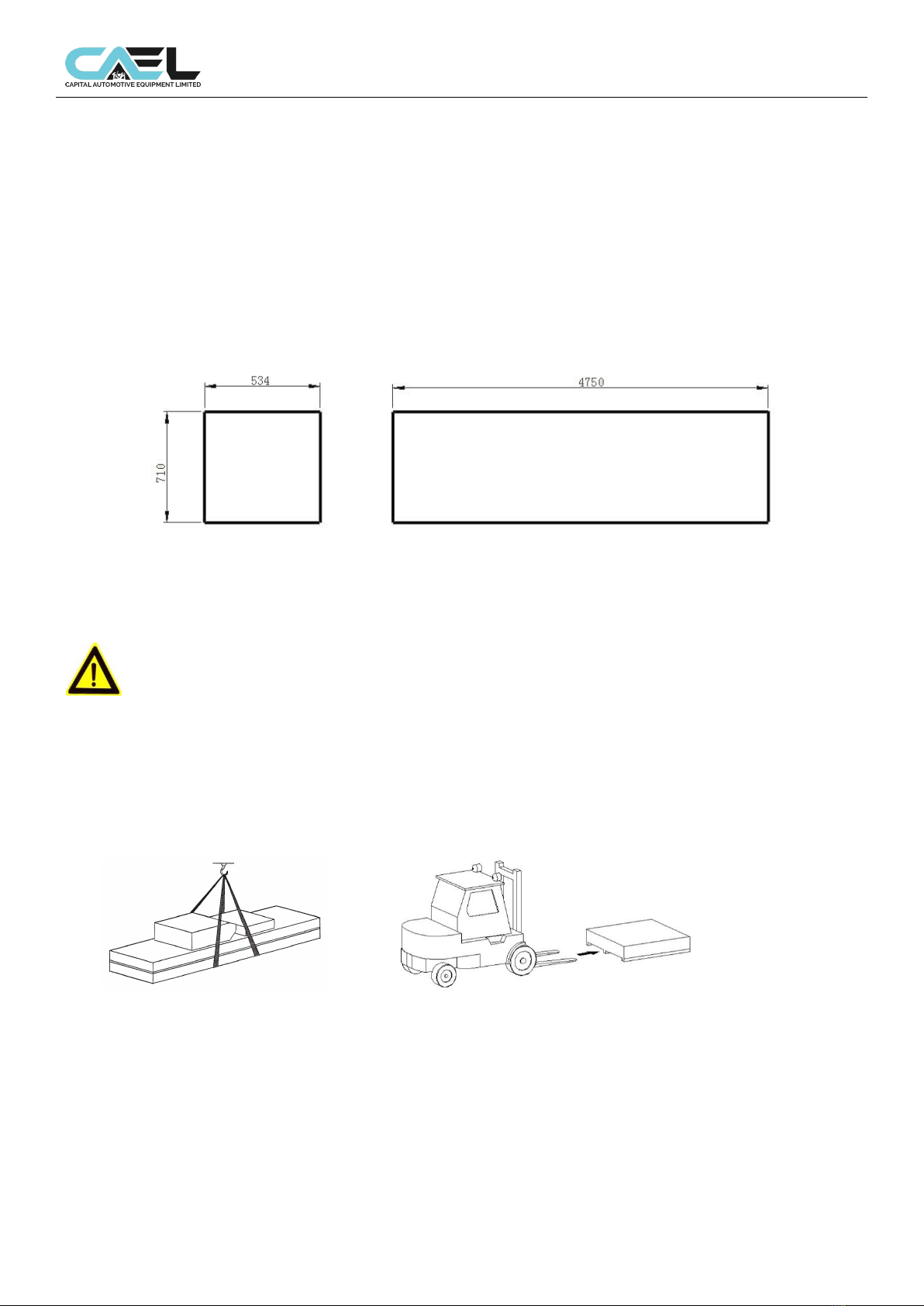
Do not attempt to install this lift if you have never been trained on basic automotive lift installation procedures. Never
attempt to lift components without proper lifting tools such as a forklift or cranes. Stay clear of any moving parts that can
fall and cause injury. These instructions must be followed to insure proper installation and operation of your lift. Failure to
comply with these instructions can result in serious bodily harm and void product warranty. Manufacturer will assume no
liability for loss or damage of any kind, expressed or implied resulting from improper installation or use of this product.

Capital Automotive Equipment Model:4PG8000
Chapter 1 Packing, transport and storage
ALL PACKING, LIFTING, HANDLING, TRANSPORT AND UNPACKING ORERATIONS ARE TO BE PERFORMED EXCLUSIVELY BY
EXPERT PERSONNEL WITH KNOWLEDGE OF THE LIFT AND THE CONTENTS OF THIS MANUL.
1.1Package
The dimension of package, please see below, and the package weight is 910kg
1.2 Transport
Packing can be lifted or moved by lift trucks, cranes or bridge cranes. In case of
slinging, a second person must always take care of the load, in order to avoid
dangerous oscillations.
During loading and unloading operation, goods must be handled by vehicles or ships. At the arrival of the goods, verify that
all items specified in the delivery notes are included. If finding missing parts, possible defects or damage due to transport,
one should examine damaged cartons according to ‘Packing List’ to verify the condition of damaged goods and missing
parts, also the person in charge or the carrier must be immediately informed. The machine is heavy goods! Don’t take
manpower load and unload and transporting way into consideration, the safety of working is important. Furthermore,
during loading and unloading operation goods must be handled as shown in the picture
Handled by crane
Handled by fork-lift truck

Capital Automotive Equipment Model:4PG8000
1.3 Storage
-The machine equipment should be stocked in the warehouse, if stocked outside should do the disposal well of
waterproof.
-Use box truck in the process of transport, use container storage when shipping.
-The control box should be placed perpendicularly during the transport; and prevent other goods from extrusion.
-The temperature for machine storage: -25ºC-- 55ºC
1.4 Opening
When the crates arrive, check that the machine has not been damaged during transport and that all parts listed are
present. The crates must be opened using all possible precautionary measure to avoid damaging the machine or its parts.
Make sure that parts do not fall from the crate during opening.

Capital Automotive Equipment Model:4PG8000
Chapter 2 Description of the machine
2.1 Introduction
The 4 post parking lifts are products of our research and development division, its special features include a lifting
capacity of 8000 lbs (3600kg).
2.2 Intend use
This Four post lift can lift various vehicles which weight is less than 8000 lbs (3600kg). And it is suitable for vehicle
test, repair, maintenance and care.
This lift is designed to lift vehicles, not for other usage.
Forbid to use for washing and spraying vehicles!
Forbid to lift vehicle which weight is over 8000 lbs (3600kg).
2.3 Layout dimension

Capital Automotive Equipment Model:4PG8000
Chapter 3 Safety caution
Read this chapter carefully and completely because it contains important information for the safety of the operator
and the person in charge of maintenance.
The lift has been designed and built for lifting vehicles and making them stand
above level in a closed area any other use is forbidden.
The manufacturer is not liable for possible damages to people, vehicles or
objects resulting from an improper or unauthorized use of the lift.
For operator and people safety, a square space for a safety area at least 1m free away from the lift must be
vacated during lifting and lowering. The lift must be operated only from the operator’s control site in this safety
area.
Operator’s presence under the vehicle, during working, is only admitted when the vehicle is lifted and the safety
lock is engaged.
Never use the lift when safety devices are off-line. People, the lift and the
vehicles lifted can be seriously damaged if these instructions are not followed.
3.1 General warnings
The operator and the person in charge of maintenance must follow accident-prevention laws and rules in force in
the country where the lift is installed.
They also must carry out the following:
Neither remove nor disconnect hydraulic, other safety devices;
Carefully follow the safety indications applied on the machine and included in the manual;
Observe the safety area during lifting;
Be sure the motor of the vehicle is off, the gear engaged and the parking brake put on;
Be sure only authorized vehicles are lifted without exceeding the maximum lifting capacity;
3.2 Safety device
To avoid overloading and possible breaking, the following safety devices have been used:
A maximum pressure valve is placed inside the hydraulic unit to prevent excessive weight.
The maximum pressure valve has been preset by the manufacturer to
a proper pressure. DO NOT try to adjust it to overrun the rated lifting
capacity.
A mechanical safety mechanism is built inside each post
It is strictly forbidden to modify any safety device. Always ensure the
safety device for proper operation during the service.
3.3 Warning labels
All safety warning signs displayed on the machine are with the purpose to draw the operator’s attention to
dangerous or unsafe situations. The labels must be kept clean and they have to be replaced if detached or
damaged. Read the meaning of the labels carefully and memorize it.

Capital Automotive Equipment Model:4PG8000
Chapter 4 Installation
Only skilled technicians, appointed by the manufacturer, or by authorized
dealers, must be allowed to carry out installation. Serious damage to people
and to the lift can be caused if installations are made by unskilled personnel.
Always refer to the exploded views attached during installation
4.1 Tools required
Rotary Hammer Drill or Similar
3/4” Masonry Bit
Hammer
4 Foot Level
Open-End Wrench Set: SAE/Metric
Socket And Ratchet Set: SAE/Metric
Hex-Key / Allen Wrench Set
Large Crescent Wrench
Large Pipe Wrench
Crow Bar
Chalk Line
Medium Flat Screwdriver
Tape Measure: 25 Foot Minimum
Needle Nose Pliers
Important notice
These instructions must be followed to insure proper installation and operation of your lift. Failure to comply with these
instructions can result in serious bodily harm and void product warranty. Manufacturer will assume no liability for loss or
damage of any kind, expressed or implied, resulting from improper installation or use of this product. Please read entire
manual prior to installation
4.2 Selecting site
Before installing your new lift, check the following.
1. LIFT LOCATION: Always use architectural plans when available. Check the layout dimension against the floor
plan requirements making sure that adequate space is available.
2. OVERHEAD OBSTRUCTIONS: The area where the lift will be located should be free of overhead obstructions
such as heaters, building supports etc.
3. DEFECTIVE FLOOR: Visually inspect the site where the lift is to be installed and check for cracked or defective
concrete.
4. Your new Two-Post lift is designed for INDOOR INSTALLATION ONLY.
4.3 Floor requirements
The lift MUST be installed on 3000 PSI concrete with the minimum thickness 150mm and an extension of at least
1.5m from anchoring points. New concrete must be adequately cured by at least 20 days minimum.
DANGERS
DO NOT install or use this lift on any asphalt surface or any surface other than concrete.
DO NOT install or use this lift on expansion seams or on cracked or defective concrete.
DO NOT install or use this lift on a second / elevated floor without first consulting building
architect.
DO NOT install or use this lift outdoors.
4.4 Installation
1. According to the instructions in the packing list, to check if is missing parts or damage pats.
2. According to 3 view drawing to install lift. Use chalk to draw the installation range of column lift.
3. After marking proper position for lift column, to draw with a rough outline of column position with chalk, column
base as a template.

Capital Automotive Equipment Model:4PG8000
4. Re-check all the dimensions to ensure that each column of the base shape and position consistent with the
chalk line.
5. Firstly, place cylinder in the positioning hole in the column bottom, then after fixing slider to slide, push the slide
to bottom of the column from top. Two columns in place to ensure that the two opposite sides of the column
spacing was equal to the length of cross beam.
6. Base on column bottom hole for position, to drill a hole about 150 mm deep with churn drill on concrete. To
ensure the expansion bolts' fixed-strength, do not get churn drill shaking when drilling hole after drilling with a
vacuum cleaner or wire brush to clean the dust of each hole. Ensure the column in the process to prevent the
dumping or shifting.
7. The nuts should be reserved 3-5mm thread after assembling expansion bolts. Inserted into the drilled hole, and
tapping with a hammer until the bolt to the column bottom of the spring washer parts, then taping pivot bolt until it
cannot move. Measured vertical degree of vertical column with squareness gauge .If column vertical degree is
large, use pad to adjust. After vertical adjustment, tighten the nut bolt.nut tightening torque is about 80N.M.
8. The lift beam is installed between two columns, with the bolts tight.
Warning: The column vertical degree must be guaranteed, otherwise it will cause lift cannot rise or damage
to person.
9. Connect equalizer steels ropes
Raise and lock each beam approximately 1m above the ground;
Make sure that the mechanical safety on each column are fully engaged before attempting to route the equalizer
cables. beams must be equal height from the floor before proceeding;
With the beams in equal height, route the equalizer cables as shown in the figure 10. Make sure the cables in the
place on the pulleys. Make sure the cables routed properly;
After the equalizer cables have been routed, adjust the nut to make each cable in equal tension by using the
adjusting wrench supplied with the lift.
10. Install lift pump unit
Attach the power unit to the POWER SIDE post. Install the vibration dampener between the power unit

Capital Automotive Equipment Model:4PG8000
and the power unit mounting plate on the Power Side post, using four M8 hex head bolts and nuts
supplied.
11. According to the hydraulic layout diagram, connect the oil pipes.
•Attach the power unit onto the support mounted on the power side column and secured with included
screws and washers.
•Route the hydraulic hoses referring the below photo.
•Tighten the fittings thoroughly.
Warning: When routing the hose, make sure to fit clips in the central position to keep the hose off the
moving steel cables under the base plate. Make sure to keep the hoses clean from dust.
12. Installation of limit switch
Fix the limit switch onto the power-side column in the position as shown in the figure 14 by using the
supplied screws.
And limit switch cable and motor cable are in parallel connection.
Raise the lift at a height of 70.8” (1800mm) to check for the proper function;
If the switch is not functioned properly, adjust the position of the switch lever
Chapter 5 Adjustment
5.1 Preparation before adjustment
Upright adjustment:
Use plumb to fix the top of post and check whether its install position is upright.
Then hammer the expanded bolt and tighten the ground bolt cap.
Only can hammer the expanded bolt after the expired period of the concrete and the gap between base
plate and ground surface must be filled with iron plate or concrete and then tighten the anchor bolts!
5.2 Process of adjustment
•Check whether the connection of power is correct, pay attention to the turning of 1 phase motor.
•Ensure all bolts are tightened enough.
•Press and HOLD “UP” button on motor, it will go up.
Press UP button on motor, the platform will go up 1 or 2 inch and lock latches leave the lock block, and
press and hold LOCK RELEAE HANDLE, then Pull the LOWERING HANDLE on the power unit until the lift
has descended completely.
•
M8 x1.25 x 35mm
hex head bolts, M8
flat washers and
M8 Nylock nuts

Capital Automotive Equipment Model:4PG8000
5.3 Synchronization adjustment
•Repeat to lift and lower the lift several times, to ensure the tensile force and balance of4 steel cables. If
not, adjust the cable nut.
5.4 Loading test
To check whether hydraulic system works normally when loading heavy weight.
Notice:
•Check every oil pipe and fitting, to ensure no leakage before operating the lift.
•Remove or install any heavy part, one should use safety support like jack to keep the balance of vehicle.
•-Cut off all the power when lift is not on work.
Notice
•ATTENTION:
•All bearings and hinges on this machine must be lubricated once a month
•The lock latch, steel cable, and some other moving parts should be lubricated monthly.
•The hydraulic oil must be replaced once a year. The oil level should always be kept at upper limit
position.
•Check the steel cable every three months and if there is some abrasion, something wrong, stops using
and contact with the manufacturer.
•Check the integration of the insurance system every day.
When change hydraulic oil, put machines to the lowest position, have the oil tank empty, when add new oil,
should be filled by filter.

Capital Automotive Equipment Model:4PG8000
Chapter 6 Operation instruction
Never operate the lift with any person or equipment below.
Never exceed the rate lifting capacity.
Always ensure that the mechanical safeties are engaged before any attempt is made to work on or near the
vehicle.
Never leave the lift in an elevated position unless the safeties are engaged.
If an anchor bolt becomes loose or any component of the lift is found to be defective, DO NOT USE THE LIFT
until repairs is made.
6.1 DEFECTS / MALFUNCTIONS
WARNING: IN CASE OF DEFECTS OR MALFUNCTIONS SUCH AS JERKY LIFT MOVEMENT OR DEFORMATION OF THE
SUPERSTRUCTURE, SUPPORT OR LOWER THE LIFT IMMEDIATELY. CONTACT QUALIFIED SERVICE PERSONNEL.
6.2 To raise the lift
Position vehicle tires in the center of each runway.
I Set parking brake or use wheel chock to hold vehicle in position.
I Before raising vehicle, be sure all personnel are clear of the lift and surrounding area. Pay careful attention
to overhead clearances.
I Raise the lift to the desired height by pressing the push button continuously on the power unit.
After vehicle is raised to the desired height, it will lower the lift autocratically on the nearest safety lock. Do
not allow cables to be remain slack.
Check to make sure all four safeties are engaged BEFORE ENTERING work area.
6.3 To lower the lift
Lock release handle on beam Lower handle on motor

Capital Automotive Equipment Model:4PG8000
Raise the lift off the safety locks by pushing the UP button on the power unit. make sure you raise the lift by
at least two inches to allow adequate clearance for the locks to clear.
Press the LOCK LEASE HANDLE and the lock latches will leave the lock blocks in post continuously.
Push the LOWERING HANDLE on the power unit until the lift has descended completely.
When lowering the lift PAY CAREFUL ATTENTION that all personnel and objects are kept clear.
ALWAYS keep a visual line of site on the lift AT ALL TIMES. ALWAYS make sure that all FOUR
LOCKS are disengaged. If one of the locks inadvertently locks on descent the lift and/or vehicle
may disrupt causing personal injury or death.
Weekly Maintenance
Lubricate all rollers with general purpose oil or WD-40.
I Check all cable connections, bolts and pins to insure proper mounting.
I Lubricate safety lock pivot points with general purpose oil or WD-40.
Monthly Maintenance
I Check safety locks to insure they are in good operating condition.
I Check all cables for excessive signs of wear
I Make a visual inspection of ALL MOVING PARTS and check for excessive signs of wear
I Replace ALL FAULTY PARTS before lift is put back into operation.
WARNING!
NEVER EXCEED THE RATED CAPACITY of lift.
DO NOT USE LIFT if any component is found to be defective or worn.
NEVER OPERATE LIFT with any person or equipment below.
ALWAYS STAND CLEAR of lift when lowering or raising.
ALWAYS INSURE SAFETY LOCKS ARE ENGAGED before entering work area.
NEVER LEAVE LIFT IN ELEVATED CONDITION unless all four safety locks are engaged.

Capital Automotive Equipment Model:4PG8000
Chapter 7 Maintenance
Cut off the power supply before servicing the lift.
The maintenance intervals indicated below apply to average workshop use. The
lift should be inspected more frequently for severe use applications.
7.1 Maintenance Schedule
Establish a periodic preventive maintenance procedure to ensure trouble free operation and long service
life.
Interval
Maintenance to be
performed on
Items
1 week
Support arms/ Disk adapters
Check rubber pads for wear.
6 months
Greasing points
Check and lubricate as required:
Slide tracks
Threads of disk adapters
Nuts of anchor bolts
Check all nuts for correct torque and
retighten them as required.
12 months
Hydraulic system
Check fluid level.
Check tightness of hoses and fittings.
7.2 Annual Inspection
We recommend having the lift inspected by qualified service personnel every 12 months.
7.3 Maintenance by the Operator
7.3.1Hydraulic System
1 Once a year check the fluid level (see below) with the lift fully lowered and add fluid as required.
2 Visually check all hydraulic hoses for tightness. Power Unit
The hydraulic fluid must be replaced periodically depending on aging, soiling
and water absorption. It is recommended to replace the pressure hoses as
required, but after six years at the latest.
Checking the Fluid Level
The fluid level can be read through the transparent reservoir at the power unit.
With the lift fully lowered, the fluid level must reach above the min level.
7.3.2 Greasing Points

Capital Automotive Equipment Model:4PG8000
The slide tracks inside the columns should be greased every six months (or
more frequently in case of noise generation)
Slide Tracks
The slide tracks inside the columns should be greased every six months (or more frequently in
case of noise generation).
1 Slightly grease the slide tracks over their whole
length using a brush.
7.3.3 Operational and Wear Checks
7.3.4 Lift Stability

Capital Automotive Equipment Model:4PG8000
1 Every six months check the nuts of all anchor bolts for correct installation torque Tinst.
2 Retighten them as required.
Installation Torque Tinst
4PG8000
80 Nm
7
.4 Cleaning
Do not use high pressure / steam jet cleaners or caustic cleaning agents.
Risk of damage!
1 Periodically wash off aggressive substances and treat the lift with oil or wax spray.
2 Repair damage to the paintwork immediately to prevent corrosion. The RAL number is
available through the manufacturer.
Chapter 8 Trouble shooting
A list of possible troubles and solutions is given below:
TROUBLE:
POSSIBLE CAUSE:
SOLUTION:
The lift does not work
The main switch is not turned on
Turn the switch on
There is no power
Check Power on to restore if
necessary
The electrical wires are disconnected
Reconnect
Fuses are blown
Check for correct voltage
Replace
The lift does not raise
The lift is overloaded
Check the vehicle weight
The motor direction of rotation is not
correct.
Interchange the two phases on
the main switch
The oil in the power unit is not sufficient.
Add some hydraulic oil
The UP button is faulty.
Check UP button and
connection for proper operation.
Replace if needed
The maximum pressure valve clogged or
leaks
Check and clean if dirty or
replace if faulty
The lowering valve does not close.
Check and clean, if dirty or
replace if faulty

Capital Automotive Equipment Model:4PG8000
The suction tube or pump filter is dirty.
Check and clean if needed.
Presence of air in the hydraulic system
Bleed the hydraulic system
The lifting capacity is not
sufficient
The pump is faulty
Check the pump and replace if
needed.
Oil leakages in hydraulic circuit
Check the circuit for any
leakage
The lift does not lower when
the lowering button is
pressed
The lowering valve does not work
properly
Check the valve and replace if
needed.
The lift does not lower
smoothly
Presence of air in the hydraulic system
Bleed the hydraulic system
Lubrication of sliders is not enough.
Grease
Sliders are damaged
Replace
The motor does not stop
when the lift reaches it
maximum height
The maximum height limit switch does not
work
Check the limit switch and
replace if needed
If the problems remain unsolved, call for technical support.
Chapter 9 Disposal of used oil
Used oil, which is removed from the power unit and the plant during an oil change, must be treated as a
polluting product, in accordance with the legal prescriptions of the country in which the lift is installed.
Chapter 10 Machine demolition
The machine must be demolished by authorized technicians, just like for assembling. The metallic parts can
be scrapped as iron. In any case, all the materials deriving from the demolition must be disposed of in
accordance with the current standards of the country in which the rack is installed. Finally, it should be
recalled that for tax purposes, demolition must be documented; submitting claims and documents
according to the current laws in the country in which the rack is installed at the time the machine is
demolished.
Table of contents
Popular Lifting System manuals by other brands

Artweger
Artweger ARTLIFT ALWA0 Series Assembly instructions

Anthony Liftgates
Anthony Liftgates ETU-20-44 Maintenance manual

Blue Giant
Blue Giant INTERLOCK CHOCK owner's manual

Haulotte
Haulotte H23TPX Technical training

3M
3M DBI SALA Flexiguard M100 User instructions

Garage Smart
Garage Smart UNIVERSAL LIFTER Installation and user guide