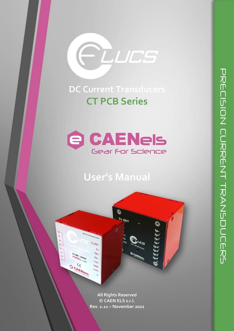
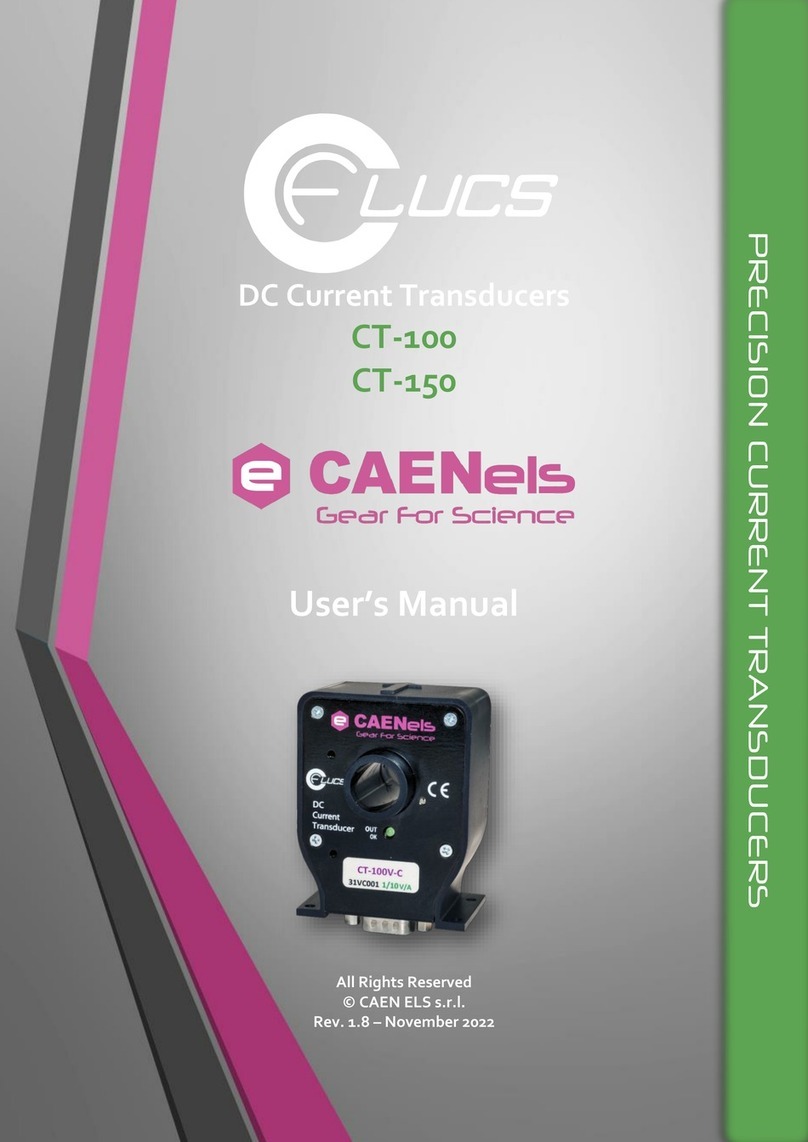
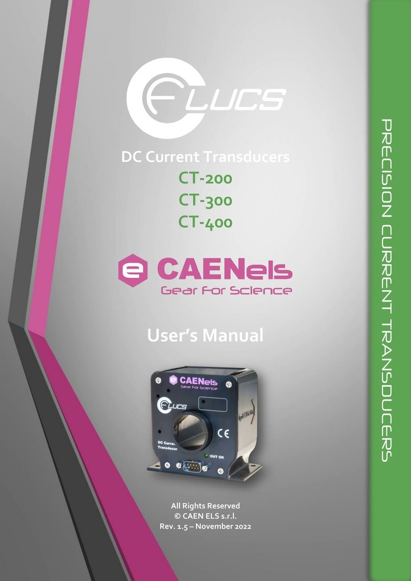
Caen ELS CT-BOX User manual

DC Current Transducers
CT-BOX
CT-BOX Viewer
Quick Start Guide
All Rights Reserved
© CAEN ELS s.r.l.
Rev. 1.1.0 –November 2022
PRECISION CURRENT TRANSDUCERS

2
CAEN ELS s.r.l.
Via Vetraia, 11
55049 Viareggio (LU) –Italy
Mail: [email protected]
Web: www.caenels.com

3
Table Of Contents
1. INTRODUCTION AND INSTALLATION......................................................5
2. QUICK START....................................................................................................6
2.1 ESTABLISHING A CONNECTION........................................................................6
2.2 DEVICE POPUP MENU .....................................................................................7
2.2.1 SETTINGS .....................................................................................7
2.2.2 FAULT .........................................................................................10
2.3 CT-BOX VIEWER MAIN WINDOW................................................................11
2.3.1 Data-Logger Mode...................................................................................11
2.3.2 Oscilloscope Mode...................................................................................12
3. CT-BOX FIRMWARE UPDATE ....................................................................14

4
Document Revision
Date
Comment
1.0.0
July 21st 2015
First Release
1.1.0
November 2022
Redesigned GUI

CT-BOX Viewer –Quick Start Guide
5
1.Introduction and Installation
The CT-BOX Viewer allows for an easy remote control of the CT-BOX using a
Graphic User Interface (GUI). The CT-BOX Viewer allows controlling one or more
CT-BOX units at the same time, acquiring and plotting current (measured through a
matched DCCT head) and temperature readings via the Ethernet interface.
The CT-BOX Viewer software is available for both Windows and Linux
platforms.
To install the CT-BOX Viewer software on Windows platforms, it is necessary
to run the installer ct-box-viewer-js Setup x.x.x.exe as Administrator. Then follow the
procedure [see Figure 1(a)]. To uninstall the software, follow the conventional
procedure from the window Start>Settings>App.
Concerning Linux platforms, the user firstly needs to make executable the file
ct-box-viewer-js-x.x.x.AppImage, either checking the box “Allows Executing file as
program” in the Properties/Permission tab when right-clicking on the file, or by the
terminal console via the command:
➢chmod +x ct-box-viewer-js-x.x.x.AppImage.
Once the file has been made executable, from the file directory, run the file as
administrator via the command:
➢sudo ./ct-box-viewer-js-x.x.x.AppImage
and then follow the procedure [see Figure 1(b)]. In this case, since the application is
portable, it is not necessary a proper uninstallation. Anyway, if the user would like to
completely remove it, remove the configuration folder $HOME/.config/ct-box-viewer-
js.
Figure 1: CT-BOX Viewer Setup for (a) Windows and (b) Linux platforms, respectively.

CT-BOX Viewer –Quick Start Guide
6
2.Quick Start
2.1 Establishing a connection
Remote communication is guaranteed by means of an Ethernet 10/100 auto-
sensing socket present on the frontal side of the CT-BOX unit.
In the CT-BOX Viewer main window (Figure 2), it is possible to add one (or
more) CT-BOX device(s) by means of the yellow hamburger menu at the left upper
corner. At the bottom of the window instead, you can select the CT-BOX viwer mode,
namely Data-Logger (set by default at the opening) or Oscilloscope. The hamburger
menu at the right-upper side gives access to either the Current and Temperature
Limits in Data-Logger mode (see Sec. 2.3.1), or the Channel and Trigger options
when in Oscilloscope Mode (see Sec. 2.3.2). Furthermore, the horizontal stripe menu
(at the right upper side of the viewer) allows an easy access to the main visualization
options (e.g. zoom, autoscale, pan) and saving options (e.g. save a screenshot of the
viewer as png, export a CSV) as well.
Figure 2: CT-BXO Viewer's Main window.
When clicking on the yellow menu hamburger, you can add a new device [Figure
3(a)] or more [Figure 3(b)] by simply typing the CT-BOX IP address.

CT-BOX Viewer –Quick Start Guide
7
Figure 3: (a) Popup menu for a new added CT-BOX. (b) More devices have been added.
Once added, a new popup menu is available for every single device. To go back at the
main window, click on the empty space of the screen.
As mentioned, it is also possible to add multiple CT-BOX units to the software
in order to control and configure them simultaneously via their corresponding popup
menu.
2.2 Device Popup Menu
The four icons in the popup menu shown in Figure 3(a) represent (starting from
the most left one):
•START/STOP the data acquisition in the currently operation mode (Data-
Logger or Oscilloscope);
•SETTINGS menu (see Sec. 2.2.1 for details);
•FAULT status, it shows the status of the connected device and eventual faults
(see Sec. 2.2.1 for details);
•CONNECT/DISCONNECT, it allows to start and stop the communication
with the connected unit (N.B. through this icon the CT-BOX is temporarily
disconnected, to definitely remove the device click on the red circle).
To go back at the main window, click on the empty space of the screen.
2.2.1 SETTINGS
GENERAL
In the GENERAL tab (see Figure 4) of the Settings window, the serial number of the
CT-BOX and the matched head (i.e. the DCCT head that must be used for the current
sensing) are shown, as well as the loaded firmware version. At the bottom, three
editable text fields are present, referred to the name of the device, the system date (in
the format mm/dd/yyyy) and the system time (in the format hh:mm:ss), respectively.

CT-BOX Viewer –Quick Start Guide
8
Figure 4: General settings tab.
NETWORK
In the NETWORK tab (see Figure 5), it is possible to change the IP address of the
CT-BOX, the relative netmask and the gateway address. In case of any change, the
CT-BOX must be added again in the viewer by following the initial procedure
explained in Sec. 2.1.
Figure 5: Network settings tab.
ACQUISITION
In the ACQUISITION tab (see Figure 6), the user can select the operation mode
(among Data-Logger and Oscilloscope) and change the relative settings, namely:
•when Data-Logger mode has been selected, it is possible to set (i) the
acquisition frequency (expressed in [Hz], N.B. resolution is 0.1 Hz), (ii) to
choose whether if acquire or not the head temperature (i.e. matched DCCT)
and the external temperature (through an external temperature sensor), (iii) as
well as to save the acquired data on an eventual SD card (if it is not already
done, it mounts the SD card, see also the SD Card Manger part in this
section). Furthermore, at the bottom, by means of the refreshing icon, it is
possible to read the instantaneous current and to reset an eventual offset after a
power cycle of the CT-BOX. This last procedure must be performed when no
primary current is flowing.

CT-BOX Viewer –Quick Start Guide
9
•concerning the Oscilloscope operation mode, the user can set the sampling
time (expressed in [s], N.B. resolution is 10 s).
In the same tab and for both operation modes, by changing the Ip-turns parameter, the
user can set the scaling factor for the primary current readings (i.e. the number of
windings of the primary conductor fed in the hole of the DCCT head).
N.B. Once back on the main window by clicking on an empty space (see Figure 2),
the highlighted mode at the bottom of the viewer must agree with the one just selected
in the Acquisition tab of the Settings.
Figure 6: Acquisition tab settings.
I/O ALARM
In the I/O ALARM tab (see Figure 7), the user can set both an I/O Trigger and the
limit values to generate an alarm, namely:
•Trigger Source Settings: when I/O Trigger checkbox is selected, there is the
possibility to choose either the Generation of an Output Trigger or the use of
External Trigger to start the acquisition;
•Alarm: when selected, it enables the alarm and the possibility to set both Upper
and Lower limits (both expressed in [A]) for the read current.

CT-BOX Viewer –Quick Start Guide
10
Figure 7: I/O Alarm tab settings.
SD CARD MANAGER
In the SD CARD tab (see Figure 8), a further icon w.r.t. previous tabs is present at
the right-bottom to mount/unmount an eventual SD card in the CT-BOX. Once the SD
Card is mounted, the user can type the name of the text file to save the acquired data.
Figure 8: SD Card Manager tab settings.
2.2.2 FAULT
The FAULT icon [normally yellow colored, in red when a fault occurs as in Figure
3(b)] reveals the status of the CT-BOX, showing eventual errors (left column) and/or
alarms (right column) when the current value is outside the limits (see I/O Alarms in
Sec. 2.2.1).
The reset button on the Status window allows to reset the Alarm and Error conditions
of the CT-BOX. Reset button is shown if and only if the CT-BOX unit is not
acquiring data.
Figure 9 shows an example of a fault condition during the CT-BOX operation:
CT-BOX Not Ready error has occurred since the unit needs an initial warm-up.

CT-BOX Viewer –Quick Start Guide
11
Figure 9: Errors and Alarms that can occur during the CT-BOX operation.
2.3 CT-BOX Viewer Main Window
Once at least one unit has been added and configured, from the Viewer Main Window
(see Figure 2) the user has to select either Data-Logger or Oscilloscope viewer mode
ensuring that it agrees with the one selected in the ACQUSITION tab in the Settings
menu (Sec. 2.2.1).
2.3.1 Data-Logger Mode
When the CT-BOX unit is connected and configured as Data-Logger mode, the plotter
on the Viewer Main Window shows the acquired current (referred to the left y-axis)
and the temperatures (referred to the right y-axis) depending on the previous
configuration. As already mentioned in Sec. 2.1, by clicking on the right hamburger
icon, a column panel on the right opens: the user can easily set both the current limits
(upper yellow box) and temperature limits (lower red box) used in the plot or use the
auto-scale function (see Figure 10). To quickly apply the auto-scale function, double-
click on the plotter (alternatively use the horizontal stripe menu, Figure 2); to come
back to the previous view, double-click again on the plotter.

CT-BOX Viewer –Quick Start Guide
12
To hide/show a single trace, click on the corresponding legend. On the other hand, to
isolate a single trace, double click on the corresponding legend.
Figure 10: Example of acquisition in Data-Logger mode (one unit has been added).
2.3.2 Oscilloscope Mode
When the CT-BOX unit is connected and configured as Oscilloscope mode, the
plotter on the Viewer Main Window shows the acquired current (expressed in [A]).
By clicking on the right hamburger menu icon, it opens the channel, the trigger and
the kind trace settings (see Figure 11).
Figure 11: Example of a window acquisition in Oscilloscope mode (two units have been added).

CT-BOX Viewer –Quick Start Guide
13
CHANNEL SETTINGS
The software treats every CT-BOX as a single channel of a conventional oscilloscope.
From the channel menu, the user can show/hide a channel, change the multiplication
scaling factor (Scale, expressed in [1/A]) and the Offset. Furthermore, the user can
enable the normalization of the signal (every channel is scaled w.r.t. its maximum of
the absolute value of the acquired window) and eventually remove its DC value (again
calculated considering the samples of the window).
COMMON AND TRIGGER SETTINGS
Once the trigger is enabled (see Figure 12), the user can add (i) the trigger Source
choosing among the added CT-BOX, (ii) the trigger Edge (positive, negative or both),
(iii) the trigger Level (expressed in [A]) and (iv) its Position on the time axes
(expressed in [sec]).
Concerning the time axes, the acquisition Window (expressed in [s]) can be changed
in the Common options section. In the same section, the user can find the RUN/STOP
indication (to easily understand the status of the current acquisition) and the trigger
MODE, that can be:
•NORMAL, it plots the signal any time the trigger condition is met, otherwise
it does not update the waveform;
•AUTO, it automatically sets a trigger configuration in order to meet the
condition;
•SINGLE, it plots the signal only the first time the trigger condition is met,
then it stops the window updating;
•STOP, it forces the stop of the window updating.
KIND SETTINS
In the Kind Settings section, the user can choose the type of the waveform among
TRACES (the current as a function of time) or its FFT (Magnitude or Phase) as a
function of the frequency.
Figure 12:Trigger options in Oscilloscope mode.

CT-BOX Viewer –Quick Start Guide
14
3.CT-BOX Firmware update
The firmware of the CT-BOX device can be updated with a USB cable and
using a Windows® OS. A specific third-party software is required to perform this
operation, which can be download from the following link:
http://www.st.com/web/en/catalog/tools/FM147/CL1794/SC961/SS1533/PF257916
After downloading the DfuSE software, simply run the installer and follow the
installation procedure. After installation, please prepare the CT-BOX for the firmware
update following the described steps:
•Switch OFF the CT-BOX unit using the main switch present on the front panel
of the device;
•Set the SWITCH #1 on the rear panel to be positioned high, as illustrated in
Figure 13;
Figure 13: SWITCH position for update firmware.
•Connect the CT-BOX to the computer using the USB cable;
•Switch ON the CT-BOX using the main switch, present on the front panel of
the unit;
•The Windows® OS shall find and install the driver for the USB port;
•Launch the DfuSe Demonstration software; this should automatically find the
DFU Device (i.e. the CT-BOX) connected to the USB port;

CT-BOX Viewer –Quick Start Guide
16
•Check the box “Verify after download”(Figure 15) and click “Upgrade”;
•The DfuSe will download the new firmware in the CT-BOX and verify the
operation;
•Switch OFF the CT-BOX;
•Set the SWITCH #1 on the rear panel to be positioned back low, as illustrated
in Figure 16;
Figure 16: SWITCH position for normal use.
•Switch ON the CT-BOX. Now the CT-BOX is updated with the new
firmware.
Table of contents
Other Caen ELS Transducer manuals
Popular Transducer manuals by other brands

KEPO
KEPO KPR-G3530 specification

Fairchild
Fairchild TT7800 Installation, operation and maintenance instructions

Gems
Gems 2200 Series Operating & installation instructions

Camille Bauer
Camille Bauer SINEAX G 537 operating instructions

S+S Regeltechnik
S+S Regeltechnik PREMASGARD 711 Series Operating Instructions, Mounting & Installation

Lumel
Lumel VTR10 user manual