Caen V560 Series Technical document

Technical
Information
Manual
MOD. V560 series
27 September 2002
Revision n. 1
16 CHANNEL
SCALERS

CAEN will repair or replace any product within the guarantee period if the Guarantor declares that the
product is defective due to workmanship or materials and has not been caused by mishandling,
negligence on behalf of the User, accident or any abnormal conditions or operations.
CAEN declines all responsibility for damages or injuries
caused by an improper use of the Modules due to
negligence on behalf of the User. It is strongly
recommended to read thoroughly the CAEN User's Manual
before any kind of operation.
CAEN reserves the right to change partially or entirely the contents of this Manual at any time and
without giving any notice.

27/09/2002 V560 User Manual
3
TABLE OF CONTENTS
TABLE OF CONTENTS...............................................................................................3
1. DESCRIPTION...............................................................................................................4
1.1. FUNCTIONAL DESCRIPTION..........................................................................4
2. SPECIFICATIONS..........................................................................................................6
2.1. PACKAGING .....................................................................................................6
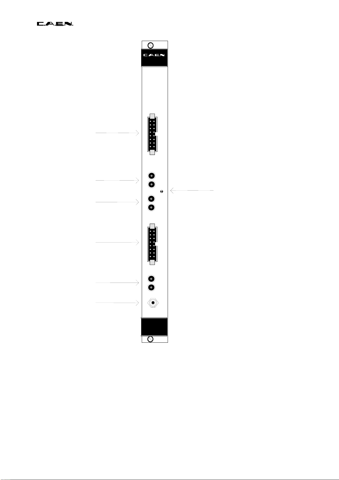
2.2. EXTERNAL COMPONENTS.............................................................................6
2.3. INTERNAL COMPONENTS..............................................................................7
2.4. POWER REQUIREMENTS...............................................................................7
2.5. CHARACTERISTICS OF THE SIGNALS..........................................................7
3. OPERATING MODES....................................................................................................10
3.1. COUNTING SCALES........................................................................................10
3.2. INTERRUPT GENERATION.............................................................................11
3.3. FRONT PANEL SIGNALS.................................................................................12
3.4. SCALE INHIBIT.................................................................................................13
3.5. SCALE CLEAR..................................................................................................13
3.6. CHANNELS TEST.............................................................................................13
3.7. MODULE CONFIGURATION............................................................................14
3.8. V560 POWER SELECTION..............................................................................14
4. VME INTERFACE...........................................................................................................16
4.1. ADDRESSING CAPABILITY.............................................................................16
4.2. DATA TRANSFER CAPABILITY.......................................................................16
4.3. MODULE IDENTIFIER WORDS.......................................................................19
4.4. SCALE STATUS REGISTER............................................................................19
4.5. SCALE INCREMENT ........................................................................................20
4.6. VETO SET/RESET............................................................................................20
4.7. CLEAR SCALES ...............................................................................................20
4.8. COUNTERS ......................................................................................................21
4.9. REQUEST REGISTER......................................................................................22
4.10. CLEAR VME INTERRUPT................................................................................22
4.11. ENABLE/DISABLE VME INTERRUPT..............................................................22
4.12. INTERRUPT LEVEL & VETO REGISTER........................................................23
4.13. INTERRUPT VECTOR REGISTER ..................................................................23
5. MOD. V560 INTERRUPTER..........................................................................................24
5.1. INTERRUPTER CAPABILITY...........................................................................24
5.2. INTERRUPT LEVEL..........................................................................................24
5.3. INTERRUPT STATUS/ID..................................................................................24
5.4. INTERRUPT REQUEST RELEASE..................................................................24
5.5. ENABLE/DISABLE INTERRUPT GENERATION .............................................24
5.6. INTERRUPT SEQUENCE.................................................................................24
6. REFERENCES...............................................................................................................26

27/09/2002 V560 User Manual
4
1. DESCRIPTION
1.1.FUNCTIONAL DESCRIPTION
The model V560 is a 1-unit wide VME module provided with 16 independent 32-bit counting channels
operating at the guaranteed input frequency of 100 MHz.
The channels are grouped in 8 section of two channels; for each section it is possible:
•to enable/disable the channels interrupt generation;
•to connect (via internal changeover switches) the two channels to obtain a single 64 bit
scale.
The module houses a VME RORA INTERRUPTER[1] that generates a VME interrupt (if enabled)
whenever the most significant bit of a scale becomes true
The module operation is fully controlled through VME. Some operations can be also performed by
three external NIM signals (indicated on the front panel connectors with "VETO", "CLEAR", "TEST"):
•VETO: (INHIBIT) an input signal sent through this connector disables the counting.
•CLEAR: (FAST CLEAR) an input signal present on this connector resets all the channels
(it is possible to perform the same operation by pressing the "MAN CLR" push-button
located on the front panel).
•TEST: if the module is configured with 16 independent channels, a pulse sent through this
connector increases all the channels.
These inputs are high impedance and each one is provided with two bridge connectors for daisy
chaining.
The module V560 is an A24/A32 D16/D32 VME slave; its Base address is fixed by 6 internal rotary
switches. A front panel LED (DTACK) lights up each time the module generates the VME signal
DTACK.
The Model uses the P1 and P2 connector of VME and optionally the auxiliary connector for the
CERN V430[2] VMEbus crate (Jaux Dataway).

27/09/2002 V560 User Manual
5
MAN CLR
CLEAR
VETO
TEST
COUNTER 2n
clock
inhibit
clear
COUNTER 2n+1
clock
inhibit
clear
IDENTIFIER
INPUT 2n+1
INPUT 2n
MSB
MSB
OE
OE
VME
INTERFACE
SCALE STATUS
REQUEST REG.
Sn
Enable n
INTERRUPTER IRQ
Req n
INT. LEVEL
STATUS /ID
Enable
to other sections
SECTION n
Clear scales
VME VETO
Increase scales
rd counter 2n
rd counter 2n+1
Fig. 1.1: Mod. V560 block diagram

27/09/2002 V560 User Manual
6
2. SPECIFICATIONS
2.1.PACKAGING
1-unit wide VME unit. Height: 6U.
2.2.EXTERNAL COMPONENTS
CONNECTORS
- No.2, "IN 0..7", "IN 8..15", 16 pin lead flat cable connector, 110Ωimpedance; for the 16 input
channels.
- No.2, "TEST", LEMO 00 type, 50Ωimpedance; two bridge connectors (for daisy chaining) for the
TEST input signal.
- No.2, "CLEAR", LEMO 00 type, 50Ωimpedance; two bridge connectors (for daisy chaining) for the
CLEAR input signal .
- No.2, "VETO", LEMO 00 type, 50Ωimpedance; two bridge connectors (for daisy chaining) for the
VETO input signal.
LEDs
- No.1, "DTACK", green, VME Selected; it lights up during a VME access.
SWITCHES
- No.1, "MAN CLR", manual clear push-button; by pushing this button:
•all the counting scales are cleared;
•the VME interrupt request (if asserted) is removed;
•the VME interrupt generation are disabled;
•the VME VETO is cleared.

27/09/2002 V560 User Manual
7
2.3.INTERNAL COMPONENTS
(refer to fig.2.2 and Appendix C - components location)
JUMPERS
- No.1, jumper "JP2"; for the -5 V power selection.
SWITCHES
- No.8, changeover switches (group "JP3..JP10"). For connect the two channels of each section to
obtain a single 64 bit scale.
- No.6, rotary switches for the module VME Base address selection.
2.4.POWER REQUIREMENTS
Crate Type + 5 V - 12 V - 5 V
Standard 2 A 160 mA ==
Type V430 2 A == 160 mA
2.5.CHARACTERISTICS OF THE SIGNALS
- INPUT CHANNELS: std. differential ECL level, 110 Ωimpedance;
max. frequency:100 MHz; min. width 5 ns;
min. time interval between two pulses: 5 ns.
- VETO(*): std. NIM level, high impedance;
min. width 50 ns;
it must precede the input channel signal by at least 35ns.
- CLEAR(*): std. NIM level, high impedance; min. width: 60 ns.
- TEST(*): std. NIM level, high impedance; max. frequency: 50 MHz;
min. width: 10 ns.
(*) These inputs are high impedance and each one is provided with two bridge connectors for daisy chaining. Note that
the high impedance makes these inputs sensitive to noise, so the chains have to be terminated on 50 Ωon the last
module; the same is needed also if one module only is used, whose inputs have thus to be properly matched.

27/09/2002 V560 User Manual
8
SCALER
16 CH
Mod. V560E
TEST input
VETO input
Inputs 8..15
Inputs 0..7
CLEAR input
Manual Clear
pushbutton
VME selected LED
SCALER
16 CH
Mod. V560E
IN
8
1
5
- +
E
A
R
L
C
T
0
E
V
S
T
E
T
A
C
T
D
K
MAN
CLR
IN
0
7
- +
Fig. 2.1: Mod. V560 Front panel

27/09/2002 V560 User Manual
9
Component side of the board
for Base address selection
Rotary switches
POWER SELECTION
JP2
JP8:sect. 7
JP10:sect. 6
JP9:sect. 5
JP7:sect. 4
JP4:sect. 3
JP6:sect. 2
JP5:sect. 1
JP3:sect. 0
VME P1 connector
VME P2 connector
Paux connector
for CERN VMEbus
crate type V430
Fig. 2.2: Mod. V560 components locations

27/09/2002 V560 User Manual
10
3. OPERATING MODES
3.1.COUNTING SCALES
The module V560 houses 16 independent 32-bit channels that are grouped in 8 sections of two
channels. For each section the two channels can be cascaded by internal changeover switches in
order to obtain a single 64-bit scale.
The picture on the following page shows the changeover switches' location and position for the
different operating modes.
For each section, the corresponding changeover switch allows the connection of the even channel to
the following one, or to the corresponding input:
If the section n is configured as two 32-bit scales:
•the clock of the channel 2n is the external input 2n;
•the clock of the channel 2n+1 is the external input 2n+1.
If the section n is configured as a single 64-bit scales,
•the clock of the channel 2n is the 32th bit of the channel 2n+1;
•the clock of the channel 2n+1 is the external input 2n +1.
The 64-bit scale obtained has the following characteristics:
•the clock input of the 64-bit scale is the external input 2n +1
•LSB of the scale value = channel 2n+1 counting value
•MSB of the scale value = channel 2n counting value
It is possible to read the status of the changeover switches via VME (see § 4.4). The table 3.1
summarizes the characteristics of the eight 64-bit scales:

27/09/2002 V560 User Manual
11
Section n single 64 bit scale configuration
Section n two 32 bit scales configuration
Component side of the board
JP8:sect. 7
JP10:sect. 6
JP9:sect. 5
JP7:sect. 4
JP4:sect. 3
JP6:sect. 2
JP5:sect. 1
JP3:sect. 0
Fig. 3.1: Mod. V560 jumper settings
Section 64-bit scale External Input Changeover sw.
number MSB LSB of the scale location
0 ch.0 ch.1 input 1 JP3
1 ch.2 ch.3 input 3 JP5
2 ch.4 ch.5 input 5 JP6
3 ch.6 ch.7 input 7 JP4
4 ch.8 ch.9 input 9 JP7
5 ch.10 ch.11 input 11 JP9
6 ch.12 ch.13 input 13 JP10
7 ch.14 ch.15 input 15 JP8
Table 3.1 Characteristics of the eigth 64-bit scales of Mod.V560
3.2.INTERRUPT GENERATION

27/09/2002 V560 User Manual
12
The operations of the V560 VME INTERRUPTER are fully software programmable; via VME it is
possible:
•to enable /disable the VME interrupt generation;
•to set the VME interrupt level;
•to program the VME interrupt vector (STATUS/ID).
Moreover for each section it is possible to enable/disable the scales interrupt generation (see § 4.9).
If the VME INTERRUPTER is enabled, it generates a VME interrupt whenever the most significant bit
of an enabled scale becomes true:
•If the section is configured with two independent 32-bit scales, it generates an interrupt when
the 32th of one of the two channels becomes true.
•If the section is configured with one 64-bit scale, it generates an interrupt when the 64th bit of
the scale becomes true (i.e., the 32th bit of the even channel).
3.3.FRONT PANEL SIGNALS
Some operations can be performed by three external NIM signals (indicated on the front panel
connectors with "VETO", "CLEAR", "TEST"):
•VETO: (INHIBIT) an input signal sent through this connector disables the counting.
•CLEAR: (FAST CLEAR) an input signal present on this connector resets all the channels
(it is possible to perform the same operation by pressing the "MAN CLR" push-button
located on the front panel).
•TEST: if the module is configured with 16 independent channels, a pulse sent through this
connector increases all the channels.
These inputs are high impedance and each one is provided with two bridge connectors for daisy
chaining.
Note that the high impedance makes these inputs sensitive to noise, so the chain has to be
terminated on 50 Ωon the last module; the same is needed also if one module only is used, whose
inputs have thus to be properly matched.

27/09/2002 V560 User Manual
13
3.4.SCALE INHIBIT
It is possible to inhibit the scales count in this way:
•by sending a NIM signal through one of the two "VETO" connectors located on the front
panel.
•by setting the VME VETO (access to the address Base +%52; see § 4.6).
The VME VETO is cleared:
•by pushing the front panel push-button "MAN CLR";
•by resetting the VME VETO (access to the address Base +%54; see § 4.6).
3.5.SCALE CLEAR
All the scales are cleared in the following cases:
•by sending a NIM signal through one of the two "CLEAR" connectors located on the front
panel;
•by pushing the front panel push-button "MAN CLR";
•by accessing via VME the address Base + %50 (Scale Clear see § 4.7);
•by generating the VME signal SYSRES.
3.6.CHANNELS TEST
If the module is configured with 16 independent channels it is possible to increment all channels:
•by sending a NIM pulse through one of the two "TEST" connectors located on the front panel.
•by accessing via VME the address Base + % 56 (Scale Increase see § 4.5).

27/09/2002 V560 User Manual
14
3.7.MODULE CONFIGURATION
The module is supplied by CAEN with the internal jumpers as shown in Figure 2.2. In this
arrangement each section is configured with two independent 32bit counting scales
At power-on:
•all the scales are cleared;
•VME VETO is cleared;
•VME interrupt is disabled.
3.8.V560 POWER SELECTION
The model V560 can be used in the standard VME crates or in the CERN VMEbus crates type V430
[2].
The module needs -5.2 V power for the ECL input stages; a jumper (JP2) is used to select the crate
type:
Standard crates:
The - 5.2 V power is generated on board from the standard voltage -12V provided on the VME
backplane.
JP2 must be located in the "- 5 EXT" position.
CERN VMEbus crate Type V430:
The - 5.2 V power is provided from a not VME standard voltage bus located on the backplane
of the crate type V430.
This backplane (VMEbus BIN type V431, see [2] § 2 ) is a monolithic printed circuit board that
provides the VMEbus standard J1 and J2 dataway and a third dataway (named "Jaux") which
is not foreseen by the VME standard.
The Jaux dataway provides some signals, the -5.2 V and -2 V requested by fast ECL logic
front end modules and the +15 V and -15 V rails. This dataway is situated in the free space
available between J1 and J2.
JP2 must be located in the "- 5 INT " position.

27/09/2002 V560 User Manual
15
VMEbus crate type V430 position (-5 EXT)
Standard crates position (-5 INT)
Component side of the board
JP2 (POWER SELECTION) settings:
Fig. 3.1: Mod. V560 JP2 settings
(
-5 INT
)
(-5 EXT)

27/09/2002 V560 User Manual
16
4. VME INTERFACE
4.1.ADDRESSING CAPABILITY
The module works in A32/A24 mode. This means that the module address must be specified in a
field of 32 or 24 bits. The Address Modifiers code recognized by the module are:
AM=%39: standard user data access
AM=%3D: standard supervisor data access
AM=%09: extended user data access
AM=%0D: extended supervisor data access
The module's Base Address is fixed by 6 internal rotary switches housed on two piggy-back boards
plugged into the main printed circuit board (see Fig. 4.1).
The Base Address can be selected in the range:
% 00 0000 <-> % FF FF00 A24 mode
% 0000 0000 <->% FFFF FF00 A32 mode
The Base Address reserves in this way a page of 256 bytes for the module. The address map of the
page is shown in table 4.1.
4.2.DATA TRANSFER CAPABILITY
The module has the following data transfer capability:
•the internal registers are accessible in D16 mode;
•the counters are accessible in D16/D32 mode.
This means that the counters can be read either by Word or Long Word instructions, while the
register can be read by Word instructions only.

27/09/2002 V560 User Manual
17
Base address bit <31..28>
Base address bit <27..24>
Base address bit <23..20>
Base address bit <19..16>
Base address bit <15..12>
Base address bit <11..8>
Fig. 4.1: Mod. V560 Base address setting.

27/09/2002 V560 User Manual
18
Table 4.1: Address Map for the Mod. V 560
ADDRESS REGISTER/CONTENT TYPE
Base + %FE
Base + %FC
Base + %FA
Version & Series
Manufacturer & Module Type
Fixed code
read only
read only
read only
Base + %5A...Base + %F8 Not used
Base + %58
Base + %56
Base + %54
Base + %52
Base + %50
Base + %4C
Base + %48
Base + %44
Base + %40
Base + %3C
Base + %38
Base + %34
Base + %30
Base + %2C
Base + %28
Base + %24
Base + %20
Base + %1C
Base + %18
Base + %14
Base + %10
Scale Status register
Scale Increase
VME VETO reset
VME VETO set
Scale clear
Counter 15
Counter 14
Counter 13
Counter 12
Counter 11
Counter 10
Counter 9
Counter 8
Counter 7
Counter 6
Counter 5
Counter 4
Counter 3
Counter 2
Counter 1
Counter 0
read only
read/write
read/write
read/write
read/write
read only
read only
read only
read only
read only
read only
read only
read only
read only
read only
read only
read only
read only
read only
read only
read only
Base + %0E
Base + %0C
Base + %0A
Base + %08
Base + %06
Base + %04
Request register
Clear VME Interrupt
Disable VME Interrupt
Enable VME Interrupt
Interrupt Level & VETO register
Interrupt Vector register
read/write
read/write
read/write
read /write
read/write
read/write
Base + %02
Base + %00 Not used
Not used

27/09/2002 V560 User Manual
19
4.3.MODULE IDENTIFIER WORDS
(Base address + %FA ,+%FC, +%FE read only)
The Three words located at the highest address on the page are used to identify the module as
shown in figure 4.1: 0123456789101112131415
V e r s i o n M o d u l e ' s s e r i a l n u m b e r Base + % FE
Address
Base + % FC
Base + % FA
Manufacturer number M o d u l e t y p e
% F A F i x e d c o d e % F 5 F i x e d c o d e
Fig. 4.2: Module Identifier words
At the address Base + % FA the two particular bytes allow the automatic localization of the module.
For the Mod. V560 the word at address Base + % FC has the following configuration:
Manufacturer N°= 000010 b
Type of module = 0000011000 b
The word located at the address Base + %FE identifies the single module through the module's
serial number and any change in the hardware, (for example the use of faster logic) will be shown by
the Version number.
4.4.SCALE STATUS REGISTER
(Base address + %58 read only)
This read-only register contains the scales' configuration of the module. The bits 0 to 7 indicates the
status of the 8 changeover switches of the 8 sections (bits 8 to 15 are unused and are read as "one"
on the VME data bus).
•bit =0 section configured with two 32-bit scales;
•bit =1 section configured as a single 64-bit scale.
The following figure shows the structure of the Scale Status register.
Sect. 3 Status
Sect. 2 Status
Sect. 1 status
Sect. 0 Status
Sect. 7 Status
Sect. 6 Status
Sect. 5 Status
Sect. 4 Status
0123456789101112131415
S3S2S1S0S7S6S5S4

27/09/2002 V560 User Manual
20
Fig. 4.3: Scale Status register
4.5.SCALE INCREMENT
(Base address + %56 r/w)
If the module is configured with 16 independent channels, a VME access (read or write) to this
location increases all the channels (same as the TEST signal).
4.6.VETO SET/RESET
(Base address + %52, Base address + %54 r/w)
A VME access (read or write) to the address Base + % 52 sets the VME VETO; the scales are not
able to count.
A VME access (read or write) to the address Base + % 54 clears the VME VETO; If no external
VETO is present, the scales are able to count.
4.7.CLEAR SCALES
(Base address + %50 r/w)
A VME access (read or write) to this location causes the following operation:
•all the scales are cleared;
•the VME interrupt request (if asserted), is removed (RORA INTERRUPTER);
•the VME interrupt generation is disabled.
Table of contents
Other Caen Media Converter manuals
Popular Media Converter manuals by other brands

Hobart
Hobart POWER MASTER Operation and maintenance manual with illustrated parts list

SIRS-E
SIRS-E Pilotino CRMX PCB instruction manual

Telecast
Telecast Viper II TR5900 user manual

GRASS VALLEY
GRASS VALLEY 8950ADC datasheet

Palmer
Palmer PDIR01 quick start guide

ADT Pulse
ADT Pulse NV412A-ADT installation guide