Vega Absolute TP-11 User manual

www.vega-absolute.ru
LORAWAN®CONVERTER
VEGA TP-11
USER MANUAL
DOCUMENT REVISION
FIRMWARE VERSION
12 2.2

Vega TP-11 / User Manual
2 Revision 12 of 12 October 2021
CONTENTS
INTRODUCTION............................................................................................................................................................................3
1 DEVICE PURPOSE AND OPERATION PRINCIPAL.................................................................................................................4
Device purpose ..........................................................................................................................................................................4
Operation algorithm .................................................................................................................................................................4
Functional ...................................................................................................................................................................................6
Marking........................................................................................................................................................................................7
2 SPECIFICATION ..........................................................................................................................................................................8
Device specification..................................................................................................................................................................8
Default device settings .............................................................................................................................................................9
3 OPERATION...............................................................................................................................................................................10
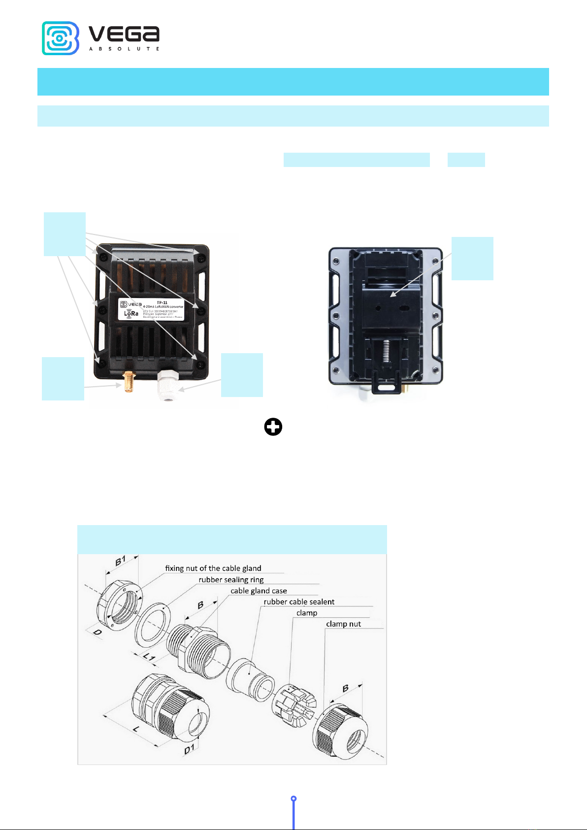
Device Appearance .................................................................................................................................................................10
Contacts ....................................................................................................................................................................................12
Indication ..................................................................................................................................................................................14
Mounting Recomendations...................................................................................................................................................15
4 COMMUNICATION PROTOCOL – version 2.0 ..................................................................................................................17
Converter TP-11 transmits the following types of packets ............................................................................................17
1. Packet with current readings .........................................................................................................................................17
2. Packet with data about state changes of the outputs OUT_1 or OUT_2...............................................................18
3. Packet with time correction request.............................................................................................................................18
4. Settings packet..................................................................................................................................................................18
Converter TP-11 receives packets of the following types ..............................................................................................19
1. Query of readings log......................................................................................................................................................19
2. Output ON command .....................................................................................................................................................19
3. Output OFF command ....................................................................................................................................................19
4. Real-time clock adjustment ...........................................................................................................................................19
5. Packet with request of settings......................................................................................................................................20
6. Packet with settings .........................................................................................................................................................20
5 STORAGE AND TRANSPORTATION REQUIREMENTS ......................................................................................................22
6 CONTENT OF THE PACKAGE ................................................................................................................................................23
7 WARRANTY................................................................................................................................................................................24

Vega TP-11 / User Manual
Revision 12 of 12 October 2021
3
INTRODUCTION
This manual is designated for Vega TP-11 device (hereinafter – device, converter)
manufactured by Vega-Absolute OOO and provides information on powering and activation
procedure, control commands and functions of the device.
This manual is targeted at specialists familiar with installation work fundamentals for
electronic and electrical equipment.
Vega-Absolute OOO reserves the right to make changes to the manual related to the
improvement of equipment and software, as well as to eliminate typos and inaccuracies,
without prior notice.

Vega TP-11 / User Manual
4 Revision 12 of 12 October 2021
1 DEVICE PURPOSE AND OPERATION PRINCIPAL
DEVICE PURPOSE
The device Vega TP-11 is designed for reading of values from devices via 4-20 mA
current loop interface and further accumulating and transmitting of this data to the
LoRaWAN®network.
Converter can be used for sensors and industrial equipment with 4-20 mA interface,
temperature sensors, waste sensors, pressure sensors.
The converter is powered by a 6400 mAh battery. The converter can be powered by
the 10…36 V external power supply.
There is a function of current value range control in the device. During device setting
while external power supplying, you may set allowed current value low and high thresholds.
When current value measurements are out of specified range then extraordinary
communication session appears. Data collection periods are set independently when
measurements are in and out of specified range.
Converter is an autonomic device and provides connected sensors with 24 V power via
4-20 mA interface.
Vega TP-11 has two ‘open-drain’ outputs so it can be used as a control device. Also,
device has two security inputs.
OPERATION ALGORITHM
Vega TP-11 operates in modes listed below:
“Storage” – is a mode for storing and transporting. In this mode the device does not
communicate regularly with the network.
“Active” – is a main mode of device operation.
Before start using you need to switch the device out of “Storage” mode.
Vega SI-22 supports two activation methods in the LoRaWAN®network - ABP and
OTAA. Select one of the methods via the “Vega LoRaWAN Configurator” application (see
“User Manual” on the program).
ABP method. After pressing the start button, the device immediately starts working in
the "Active" mode.
OTAA method. After pressing the start button, the device makes three attempts to
connect to the network within the set frequency plan. After the activation in the LoRaWAN®
network is confirmed, the device sends a signal (LED flashing for 5 seconds) and switches to

Vega TP-11 / User Manual
Revision 12 of 12 October 2021
5
the "Active" mode. If all attempts fail, the device will continue to accumulate data and will
attempt to connect to the network every 6 hours.
Hold the start button pressed (min. 5 seconds) to switch the device from the "Active"
mode back to the "Storage" mode without turning off the power (battery or external).
The device forms the data packet with current state with a configurable period from 5
minutes to 24 hours. The packets stored in the device memory and transmitting during the
next communication session with the LoRaWAN®network.
Examples
If the data collection period is set to 24 hours the packet is formed at 00.00 on the
internal clock of the device
If the data collection period is 12 hours then at 00.00 and at 12.00, and so on.
Data collection period when measurements are out of specified current value range set
independently and may be equal from 5 minutes to 24 hours.
The adjustable data transfer period can be from 5 minutes to 24 hours. When
beginning of communication session, the device starts sending packets with readings from
the earliest packet. The time of data transmitting cannot be specified, it’s defined in random
way for every device in chosen period of transmission from the moment of connection to the
network.
Example
Transmission period is 30 minutes, and device was started at 16:40 by the internal
device clock. In random way the device calculate data transmitting time and set it at 16:41 in
the half-hour period from 16:40 to 17:10. Thus, packets from this device will transmit at 16:41,
at 17:11, at 17:41, at 18:11 and so on every 30 minutes by the internal device clock.
When measurements are out of specified current value range the communication
period still the same if parameter “Immediately send data when current is out of range” is not
active.
If that parameter is active and external power supplying, then the alarm message will
be forming and sending during 2 minutes after the moment of current value measurements
are out of specified range. If external power not supplying, then the converter will detect
exceeding the specified limits during the following data collection session according to the
schedule only, but the modem will send that data immediately too. Every following message,
which will form according to the data collection period, also will have sent immediately until
the current value measurements are back in range.
Current value range set in the “Vega LoRaWAN Configurator” application with
parameters “Current low threshold” and “Current high threshold”. Current threshold set in mA
multiplied by 100.

Vega TP-11 / User Manual
6 Revision 12 of 12 October 2021
Example
In the device settings the low threshold value is 200 and high – 2500. It means the low
threshold of current value is 2 mA and high is 25 mA.
The internal clock is set automatically when you connect to the device through USB,
also can be adjust via LoRaWAN®network.
FUNCTIONAL
Vega TP-11 converter can be either of class A or class C (LoRaWAN classification) and
has the following features:
Automatic change from A class to C class when powered from an external
power supply
ADR support (Adaptive Data Rate)
Sending of confirmed packets (configurable)
Extra communication in case of security inputs actuation
Extra communication in case of current value measurements are out of specified
range
Temperature measurement by the internal temperature sensor
Charge measuring of the built-in battery (%)
Ability to configure security input triggering on short, open or both cases
Ability to set different data collection period for case of current value
measurements are out of specified range
Immediately data sending at moment of message forming for case of current
value measurements are out of specified range

Vega TP-11 / User Manual
Revision 12 of 12 October 2021
7
MARKING
Device marked with sticker that contain the next information:
Device model;
DevEUI;
Month and year of manufacture.
Sticker located in three places – on device case, in factory certificate and on the packing
box.
Besides, there is an additional sticker located on the packing box which contains:
Information about firmware version;
QR-code containing keys for device activation in the LoRaWAN®network and
other IDs.

Vega TP-11 / User Manual
8 Revision 12 of 12 October 2021
2 SPECIFICATION
DEVICE SPECIFICATION
MAIN
Current loop 4-20 mA interface 1
Security inputs
2
‘Open-drain’ outputs
2
Accuracy of current measurement ±1.2 %
USB-port mini-USB, type B
Operating temperatures
-40…+85 °С
LORAWAN®
LoRaWAN
®
class
A or С
Quantity of LoRa channels
16
Frequency plans supported by default
RU868, EU868, KZ865, custom (EU868
based)
Frequency plans available as order option
IN865, AS923, AU915, KR920, US915
Activation type ABP or OTAA
Communication period 5, 15, 30 minutes, 1, 6, 12 or 24 hours
Data collection period 5, 15, 30 minutes, 1, 6, 12 or 24 hours
Memory amount for storing packets 200 packets
Type of the LoRa antenna external, SMA connector
Sensitivity -138 dBm
Radio coverage in restrained urban conditions max 5 km
Radio coverage within line of sight max 15 km
Transmitter power by default 25 mW (configurable)
POWER
Built-in battery 6400 mAh
External power supply 10…36 V
4-20 mA interface power supply 24 V
Calculated number of packets sent by the
device while default settings
15,000
CASE
Housing dimensions, no more than 93 х 78 х 66 mm
Ingress protection rating IP65
Mounting
clamp fastening to the support, DIN-rail,
wall-mounting
PACKAGE
Dimensions 140 х 80 х 85 mm
Weight 0.270 kg

Vega TP-11 / User Manual
Revision 12 of 12 October 2021
9
DEFAULT DEVICE SETTINGS
PARAMETER
VALUE
Frequency plan RU868
Activation type OTAA
Adaptive Data Rate ON
Confirmed Uplinks OFF
Rx 1 Delay
1 second
Join Accept Delay 5 seconds
Uplink number of transmissions 1
Data rate DR0
Power 14 dBm
Communication period 24 hours
Data collection period 24 hours
Data collection period when temperature is
out of range
1 hour
Time zone
UTC +00:00
Inputs operate in mode
pulse
For changing the device settings, you need to connect to it with “Vega LoRaWAN
Configurator” application. You can download app on the iotvega.com site in SOFT section as
well as User Manual for configurator. Go to the app page.

Vega TP-11 / User Manual
10 Revision 12 of 12 October 2021
3 OPERATION
DEVICE APPEARANCE
Vega TP-11 is represented in black plastic case which has six screws and mounting for
DIN-rail. The device case is equipped with a hermetic gland of M12 size. A sealant is installed
inside the gland, ensuring compliance with the declared Ingress Protection rating of the
device case.
1 – screws ø 3 mm х 16 mm, cross
2 – DIN-rail with mounting holes ø 3 mm
3 – input of external antenna
4 – cable gland of M12 size for installing the cables and wires with circular cross-
section with a diameter of 5...6 mm.
2
1
4
3
Internal structure of cable gland

Vega TP-11 / User Manual
Revision 12 of 12 October 2021
11
All of elements for manage and indication as well as connecting contacts are placed on
the board inside the case.
5
6
7
8
9
10
5 – input for connecting
an external antenna
6 – start button
7 – LED indicator
8 – contacts
9 – USB-port
10 – connector for battery

Vega TP-11 / User Manual
12 Revision 12 of 12 October 2021
CONTACTS
Converter has 10 contacts, see table below:
Contact
Designation on the board
Description
1
OUT_2
Open-drain output 2
2
OUT_1 Open-drain output 1
3
+VPWR Power “+”
4
Ʇ
Power “-“
5
CL- 4-20 mA “-“
6
CL+ 4-20 mA “+”
7
COUNT_2 Security input 2
8
Ʇ
Ground
9
COUNT_1 Security input 1
10
Ʇ
Ground
Ground Ʇcontacts 8 and 10 are used for connection of security inputs COUNT_1 and
COUNT_2.
Security inputs of the device are used to connect circuits with the following types of
NO contacts:
reed switch (Herkon);
mechanical pushbutton;
open-drain output.
While security input connected the device monitors its state change (closure/unlocking
or both of it – depend on the settings). Should the security input triggering, the device is
activated and sends an alarm message to the network.

Vega TP-11 / User Manual
Revision 12 of 12 October 2021
13
For connect an external sensor contacts CL+ и CL- are used. Connection scheme see
on the picture below.
To save the battery life of the converter, the 24 V supply voltage is not continuously
supplied. The 24 V voltage is applied to the 4-20 mA device a few seconds before the polling
is performed so that the sensor can turn on and set the current corresponding to the
measured parameter. This time, the so-called "startup time", is a configurable parameter from
the configurator and can be set from 1 to 60 seconds.
The outputs OUT_1 and OUT_2 operate on the principle of open-drain and can be
used to control external devices, such as electric cranes, lighting, sirens and so on. The load
capacity of each output is no more than 200 mA.
Permissible load for each digital output is 200 mА
To increase the load on the device outputs, it is necessary to use an external relay. The
relay connection scheme is shown below.

Vega TP-11 / User Manual
14 Revision 12 of 12 October 2021
INDICATION
There is a one red LED on the board. The indication is only used when the device is
activated in the LoRaWAN network and when the operating modes are changed.
LED SIGNAL
MEANING
Short flashings Linking to the network in progress
One long flashing
during 5 sec
The device has been successfully
connected to the network and is in
active mode
Three flashings each by
1 sec
Linking to the network has been failed
or the device switched to the
“Storage” mode
In case of connection attempt fail, the device will continue to accumulate
data and will attempt to connect to the network every 6 hours
LED on the board

Vega TP-11 / User Manual
Revision 12 of 12 October 2021
15
MOUNTING RECOMENDATIONS
To provide the stable radio between the gateway and the end device it is
recommended avoiding the device installation in the places which are barriers for the radio
signal getting through like a reinforced floors and walls, a basement, an underground facilities
and wells, a metal case etc.
The necessary stage for the network deploying including a big quantity of end devices
is a radio planning work with nature experiments.
For mounting you will need:
wire stripper;
laptop.
Step by step mounting be like:
1. Setting the devices and connecting them to the network are usually carried out in
the office (see Network Deployment Manual).
2. Determination of suitable places for mounting at the object with a network tester.
3. De-energizing the connected equipment, metering devices, etc.
4. Placement the wires in the cable gland. It must be remembered that the wires must
be united in one cable of circular cross-section with diameter of 5…6 mm.
Inside the cable gland there is a sealant ensuring compliance with the
declared Ingress Protection rating of the device case. When removing the
sealant, as well as when installing wires of a different diameter or cross-
section, device performance may deteriorate until failure due to moisture
entering the case
5. Connecting all necessary wires to the TP-11 contacts.
6. TP-11 converter can be powered from an external power source as well as from a
battery. For working with battery, it is necessary to connect it to battery connector

Vega TP-11 / User Manual
16 Revision 12 of 12 October 2021
on the board. For working with external power source you should use the contacts
+VPWR and Ʇ.
7. When the power is connected at the first time the device automatically switches to
the “Active” mode and starts registration in the network. But if the device with
connected battery or an external power has been switched to the “Storage” mode
(by the pressing on the start button more than 5 sec) then you need to press the
button to start.
8. By the laptop make sure that the device successfully sends the data.
9. Assembling the device.
10. DIN-rail mounting or another available way to mount the device on the object.
Before connecting the device to the network, make sure that its
registration data is entered in the network - Device EUI, Application EUI
and Application Key for OTAA, or Device address, Application session key
and Network session key for ABP
Connector for
battery
Contacts for
connecting an
external power
source
Start button on the
board

Vega TP-11 / User Manual
Revision 12 of 12 October 2021
17
4 COMMUNICATION PROTOCOL – version 2.0
This part describes the TP-11 data exchange protocol with LoRaWAN®network.
In fields consisting of several bytes, the little-endian byte order is used
CONVERTER TP-11 TRANSMITS THE FOLLOWING TYPES OF PACKETS
1. Packet with current readings
From connected heat meter, sent regularly or by the request or by the one of “Reason
of sending message” field events.
Size in bytes
Field description
Data type
1 byte Packet type, this packet == 1 uint8
1 byte Battery level, % uint8
1 byte Over limits («0» – there is no, «1» - there is) uint8
4 byte Time of current readings in that packet (unixtime UTC) uint32
1 byte Current device temperature int8
2 bytes Current low threshold (mА*100) uint16
2 bytes Current high threshold (mА*100) uint16
1 byte Reason of sending message uint8
1 byte TP-11 inputs/outputs state uint8
2 bytes Measurement current of connected sensor (mA*100) uint16
“Reason of sending message” field codes
Code
Value
0x00
Sending packet by the time
0x01
By the security input 1 triggering
0x02
By the security input 2 triggering
0x03
External power state was change
0x04 Measurement is out of the specified limits
0x05 Transmitting by the request
"Inputs/outputs state" bit field decoding
Bits
Field description
0 bit Power (0 – battery, 1 – external)
1 bit Security input 1 (0 - unclosed, 1 – closed)
2 bit
Security input 2 (0 - unclosed, 1 – closed)
3 bit
Output 1 (0 – off, 1 – on)
4 bit
Output 2 (0 – off, 1 – on)
5 bit
reserve (always 0)

Vega TP-11 / User Manual
18 Revision 12 of 12 October 2021
6 bit reserve (always 0)
7 bit reserve (always 0)
2. Packet with data about state changes of the outputs OUT_1 or OUT_2
Size in bytes
Field description
Data type
1 byte Packet type, this packet == 5 uint8
1 byte Battery charge, % uint8
1 byte Output number (1 или 2) uint8
1 byte Output state (0 - off, 1 - on) uint8
4 bytes Time of the modem at a moment of the packet
transmission (unixtime UTC)
uint32
3. Packet with time correction request
Sent every seven days on LoRaWAN port 4.
Size in bytes
Field description
Data type
1 byte
Packet type, this packet == 255
uint8
4 bytes Time of the modem at a moment of the packet
transmission (unixtime UTC)
uint32
After receiving this type of package, the application can send to modem the packet with
time correction.
4. Settings packet
Transmitting on LoRaWAN port 3 when settings request command received, or device
connected to the network.
Size in bytes
Field description
Data type
1 byte Packet type, this packet == 0 uint8
2 bytes ID of parameter uint16
1 byte Data length (len) uint8
len bytes Parameter value -----
2 bytes ID of parameter uint16
1 byte Data length (len) uint8
len bytes Parameter value -----
… … …
2 bytes ID of parameter uint16
1 byte Data length (len) uint8
len bytes Parameter value -----

Vega TP-11 / User Manual
Revision 12 of 12 October 2021
19
CONVERTER TP-11 RECEIVES PACKETS OF THE FOLLOWING TYPES
1. Query of readings log
Send by application on LoRaWAN port 2.
Size in bytes
Field description
Data type
1 byte Packet type, this packet == 2 uint8
Upon receiving this package, the converter will perform an extraordinary polling of
connected sensor and send packet with current state.
2. Output ON command
Send by application on LoRaWAN port 2.
Size in bytes
Field description
Data type
1 byte
Packet type, this packet == 3
uint8
1 byte Output no. (1 - 2) uint8
1 byte Output ON for the time in seconds (1…255), (0 – forever
ON).
uint8
Upon receiving this package TP-11 will close the correspond output and transmits the
packet with current readings.
3. Output OFF command
Send by application on LoRaWAN port 2.
Size in bytes
Field description
Data type
1 byte
Packet type, this packet == 5
uint8
1 byte
Output no. (1 - 2)
uint8
Upon receiving this package TP-11 will unclose the correspond output and transmits
the packet with current readings.
4. Real-time clock adjustment
Send by application on LoRaWAN port 4.
Size in bytes
Field description
Data type
1 byte
Packet type, this packet == 255
uint8
8 bytes
The value in seconds for which you need to adjust the
time.
Can be positive or negative
int64

Vega TP-11 / User Manual
20 Revision 12 of 12 October 2021
5. Packet with request of settings
Sent by application on LoRaWAN port 3.
Size in bytes
Field description
Data type
1 byte Packet type, this packet == 1 uint8
Answering that packet, the device sent the packet with settings.
6. Packet with settings
Is identical to such packet from device.
Size in bytes
Field description
Data type
1 byte Packet type, this packet == 0
2 bytes ID of parameter uint16
1 byte Data length (len) uint8
len bytes Parameter value -----
2 bytes ID of parameter uint16
1 byte Data length (len) uint8
len bytes Parameter value -----
… … …
2 bytes ID of parameter uint16
1 byte Data length (len) uint8
len bytes Parameter value -----
The package with settings sent to the device may not contain all the settings supported
by the device, but only the part that needs to be changed.
Table of ID of TP-11 parameters and these possible values
ID of
parameter
Description
Data length
Possible values
4 Confirmed uplinks 1 byte 1 – confirmed
2 – unconfirmed
5 Adaptive data rate 1 byte 1 – on
2 – off
8 Uplinks number of transmissions 1 byte from 1 to 15
16 Communication period 1 byte 1 – 1 hour
2 – 6 hours
3 – 12 hours
4 – 24 hours
5 – 5 minutes
6 – 15 minutes
7 – 30 minutes
38
Guard input 1, Send alarm message
1 byte
1 – on short
2 – on open
Other manuals for TP-11
1
Table of contents
Other Vega Absolute Media Converter manuals
Popular Media Converter manuals by other brands

ISOIL
ISOIL ISOMAG ML 145 Operating and maintenance manual

Monoprice
Monoprice VD-101 user manual

Terahertz Technologies
Terahertz Technologies TIA-2000 operating instructions

Speaka Professional
Speaka Professional 1230712 operating instructions

LevelOne
LevelOne Infinity IEC-1020 Quick installation guide

AMX
AMX MAX-CSE installation guide

B+B SmartWorx
B+B SmartWorx IE-MultiWay user manual

Cypress
Cypress DCT-4T Operation manual

Microchip Technology
Microchip Technology dsPIC33F Family Reference manual

National Instruments
National Instruments NI PXI-5600 Getting started guide

M-system
M-system 18TG instruction manual

Elko
Elko RFIM-20B quick start guide