Caen A3484 Technical document

Technical
Information
Manual
MOD. A3484/A3485
AC/DC CONVERTER 400 V
3-PHASE 48 V 2.5/5 KW
MANUAL REV. 3
4 July 2017
Revision n. 3
NPO:
00120/04:A348x.MUTx/03

CAEN will repair or replace any product within the guarantee period if the Guarantor declares that the
product is defective due to workmanship or materials and has not been caused by mishandling,
negligence on behalf of the User, accident or any abnormal conditions or operations.
CAEN declines all responsibility for damages or
injuries caused by an improper use of the Modules due
to negligence on behalf of the User. It is strongly
recommended to read thoroughly the CAEN User's
Manual before any kind of operation.
CAEN reserves the right to change partially or entirely the contents of this Manual at any time and
without giving any notice.
Disposal of the Product
The product must never be dumped in the Municipal Waste. Please check your local
regulations for disposal of electronics products.

Document type:
Title:
Revision date:
Revision:
User's Manual (MUT)
A3484-A3485 AC/DC Converter 400 V 3-phase 48 V 2.5/5kW
04/07/2017
3
NPO:
Filename:
Number of pages:
Page:
00120/04:A348x.MUTx/03
A3485_REV3.DOC
21
3
TABLE OF CONTENTS
1. EASY EMBEDDED ASSEMBLY SYSTEM ..............................................................................................5
1.1 FUNCTIONAL DESCRIPTION .......................................................................................................................5
1.2 THE CAEN MULTICHANNEL POWER SUPPLY SYSTEM OVERVIEW...........................................................6
1.3 THE MOD.A1676A BRANCH CONTROLLER OVERVIEW............................................................................8
2. MOD. A3484 AND A3485 AC/DC CONVERTERS...................................................................................9
2.1 FRONT PANEL COMPONENTS...................................................................................................................10
2.1.1 OUTPUT± .....................................................................................................................................................10
2.1.2 Power/Monitor ..............................................................................................................................................10
2.1.3 EASY BUS......................................................................................................................................................11
2.1.4 Interlock.........................................................................................................................................................11
2.1.5 48V IN............................................................................................................................................................12
3. SAFETY INFORMATION AND INSTALLATION REQUIREMENTS ..............................................13
3.1 GENERAL SAFETY INFORMATION ............................................................................................................13
3.1.1 Injury Precautions.........................................................................................................................................13
3.2 SAFETY TERMS AND SYMBOLS ON THE PRODUCT ..................................................................................13
3.3 INSTALLATION........................................................................................................................................14
4. OPERATING MODES ...............................................................................................................................15
4.1 OUTPUT CONTROL AND MONITORING......................................................................................................15
4.1.1 Internal Channel OPC Items .........................................................................................................................17
4.1.2 Output Channel OPC Items...........................................................................................................................18
LIST OF FIGURES
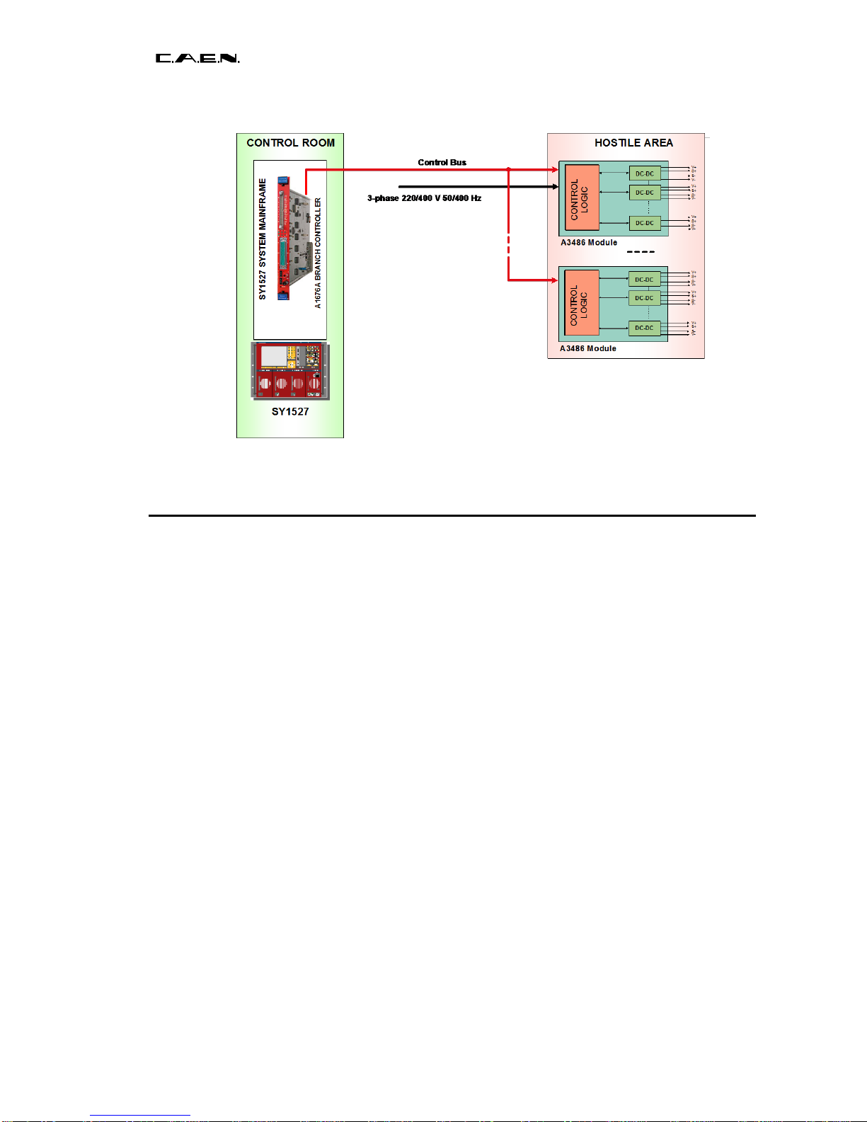
FIG.1.1 –SYSTEM’S BLOCK DIAGRAM......................................................................................................................6
FIG.2.1 –MOD.A348X FRONT PANEL .....................................................................................................................9
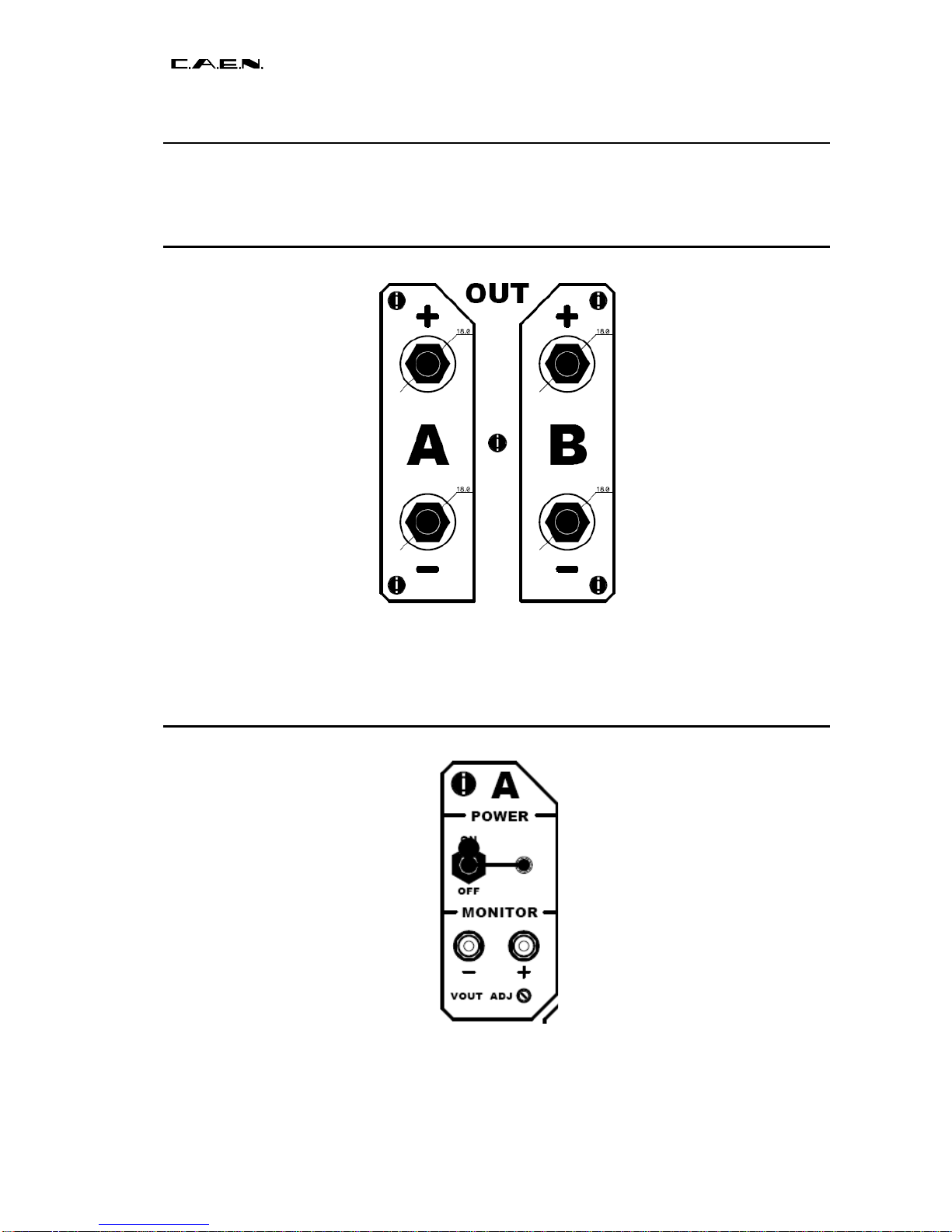
FIG.2.2 –OUTPUT± SECTION...............................................................................................................................10
FIG.2.3 –OUTPUT± SECTION...............................................................................................................................10
FIG.2.4 –EASY BUS SECTION..............................................................................................................................11
FIG.2.5 –INTERLOCK SECTION...............................................................................................................................11
FIG.2.6 –INTERLOCK DIAGRAM.............................................................................................................................12
FIG.2.7 –48V IN SECTION.....................................................................................................................................12
FIG.2.8 –A3484/A3485 GROUND SCHEMES..........................................................................................................12

Document type:
Title:
Revision date:
Revision:
User's Manual (MUT)
A3484-A3485 AC/DC Converter 400 V 3-phase 48 V 2.5/5kW
04/07/2017
3
NPO:
Filename:
Number of pages:
Page:
00120/04:A348x.MUTx/03
A3485_REV3.DOC
21
4
LIST OF TABLES
TABLE 1.1 –TECHNICAL SPECIFICATIONS OF THE SY 1527 MAINFRAME ..................................................................7
TABLE 2.1 –TECHNICAL SPECIFICATIONS OF THE A3484 AND A3485 48 VPOWER SOURCES..................................9
TABLE 4.1 –CH0 PARAMETERS (BOARD PARAMETERS)........................................................................................15
TABLE 4.2 –CH1..2 PARAMETERS (OUTPUT CHANNEL PARAMETERS) ...................................................................16
TABLE 4.3 –STATUS WORD SIGNIFICANT BITS........................................................................................................16
TABLE 4.4 –INTERNAL CHANNEL ITEMS................................................................................................................18
TABLE 4.5 –OUTPUT CHANNEL ITEMS...................................................................................................................20

Document type:
Title:
Revision date:
Revision:
User's Manual (MUT)
A3484-A3485 AC/DC Converter 400 V 3-phase 48 V 2.5/5kW
04/07/2017
3
NPO:
Filename:
Number of pages:
Page:
00120/04:A348x.MUTx/03
A3485_REV3.DOC
21
5
1. EASY Embedded Assembly System
1.1 Functional description
EASY (Embedded Assembly SYstem) is the new CAEN power supply solution for
operation in magnetic field and radioactive environment. CAEN has been involved for
more than a decade in developing different solutions for the main LHC experiments,
where the electronic equipment of the experiment is dealing with high dose radiation and
intense magnetic field. In order to provide safe and reliable operations in such hostile
areas, CAEN started tests with rad-tolerant components and magnetic field resistant
solutions, patenting the new technology that is now used in this new line of products.
Moreover, though designed for harsh environment, the EASY modules can work also in
normal condition with excellent performance. In the new architecture, the power supply
can be located directly in the hostile area, where the EASY modules provide a wide
variety of output voltages to satisfy the requirements of most detectors and front-end
electronics. The control of the EASY power supply system is done remotely using a
Branch Controller (Mod. A1676A) plugged in a SY1527 or SY2527 mainframe located in
the control room. Each A1676A branch controller can handle up to 6 EASY crates: in this
way, one SY1527 power supply system, for example, housing up to 16 A1676A boards,
can handle up to 96 EASY systems. The EASY crate can house up to 10 boards,
depending on the boards’ width. The branch controller is the interface between the
mainframe (SY1527 or SY2527) and the remote boards in the EASY crate: its role is to
configure the EASY channels as if they belong to the supply unit slot in which the branch
controller is located. All the channels of the EASY boards will be considered as channels
of the branch control board, thus hugely increasing the number of channels the system
can handle. Through the mainframe, the provided and fully reliable OPC server permits
an immediate and “automatic” interfacing with the custom control software; moreover, a
C-library for Windows and Linux is available as well. The EASY crate can be used with an
air and/or water intercooler and its standard width fit the rack mounting. Fig. 1.1 shows
the system’s block diagram.

Document type:
Title:
Revision date:
Revision:
User's Manual (MUT)
A3484-A3485 AC/DC Converter 400 V 3-phase 48 V 2.5/5kW
04/07/2017
3
NPO:
Filename:
Number of pages:
Page:
00120/04:A348x.MUTx/03
A3485_REV3.DOC
21
6
Fig. 1.1 –System’s block diagram
1.2 The CAEN Multichannel Power Supply System Overview
The SY1527 system is the fully equipped experiment version of a new line of power
supply systems which represent CAEN's latest proposal in the matter of High Voltage and
Low Voltage Power Supplying. This system outlines a completely new approach to power
generation and distribution by allowing the housing, in the same mainframe, of a wide
range of boards with different functions, such as High/Low Voltage boards, generic I/O
boards (temperature, pressure monitors, etc.) and branch controllers, where the latter are
used to control other remote generators and distributors. Modularity, flexibility and
reliability are the key-points of its design, enabling this module to meet the requirements
needed in a wide range of experimental conditions, which range from those of LHC
experiments, where the features of this model find prior application, to those of other less
challenging, but still demanding, High Energy Physics experiments.
The mainframe is housed in a 19"-wide, 8U-high euro-mechanics rack and hosts four
main sections:
-the Board Section, with 16 slots to house boards, distributors and branch controllers;
-the Fan Tray Section, housing 6 fans arranged on two rows;
-the Power Supply Section, which consists of the primary power supply and up to 3
power supply units;
-the CPU and Front Panel Section which includes all interface facilities.
The User Software Interface features the usual friendliness of the previous CAEN
systems which now also includes a 7.7" colour LCD. A wide choice of interface facilities
provides full communication compatibility with the previous systems and the feasibility of
controlling heterogeneous external devices. Modularity has been one of the leading
criteria in the design and development of the system: both the Power Supply Section and
the Board Section are completely modular. The Power Supply Section allows different
configurations with up to 3 power supply units per mainframe (up to 2250 W), while the
Board Section can house up to 16 boards able to fulfil different functions. A complete line
of power supply boards and distributors has been specially developed for this new
system. The minimum system configuration consists of the primary power supply, one

Document type:
Title:
Revision date:
Revision:
User's Manual (MUT)
A3484-A3485 AC/DC Converter 400 V 3-phase 48 V 2.5/5kW
04/07/2017
3
NPO:
Filename:
Number of pages:
Page:
00120/04:A348x.MUTx/03
A3485_REV3.DOC
21
7
Power Supply Unit and one board. The system allows also to deal with power supply
solutions composed by “branch controllers” (housed in the system main frame) and on-
detector “remote boards” (manufactured in order to be magnetic field and radiation
tolerant). Channel trip control on other crates is performed via four external differential trip
lines. A sophisticated trip handling via software allows to control and correlate trip
conditions on the channels of the crate as well as of other crates connected to it. Live
insertion and extraction of the boards, which reduces the down time of the global system,
and easy access to the computing core and peripherals of the system complete the
system flexibility. Easy interfacing is another key-point of the SY1527 system, which can
be connected to SY127 and SY527 systems. The Ethernet interface (TCP/IP) allows both
an easy Telnet access and the connection via OPC Server to a SCADA control system.
Enhanced software programming features a unified command set independent from the
interface used to communicate with the system. The Power Supply Section and Board
Section can be externally synchronised via front panel connectors. Multi-layered access
to the system via Intranet is foreseen through the management of several custom user
profiles. In particular, three different access levels have been implemented: Guest, User
and Administrator, each of which with password protection. Handy maintenance and
upgrading, which constitute a major issue in the reliability of a system, are further
guaranteed by the possibility of accessing and servicing the system via network facilities.
Actually, the Telnet access facility allows remote debugging and technical support of the
system, including future firmware upgrading. For a detailed description of the SY 1527
Universal Multichannel Power Supply System please refer to the SY 1527 User's Manual.
Table 1.1 –Technical specifications of the SY 1527 mainframe
Packaging
- 19"-wide, 8U-high Euro-mechanics rack;
- Depth: 720 mm.
Weight
-Mainframe (*): 24 kg
-Mod. A1532: 3.2 kg
Power requirements
Voltage range: 100/230 V
Frequency: 50/60 Hz
Power: 3400 W
Max. number of boards per crate
16
Max. nr. of power supply units per crate
3
Primary power supply output (Mod.
A 1531)
12 V, 8 A
+5 V, 20 A
Power supply unit output (Mod. A 1532)
+48 V, 15.6 A
Max. output power
2250 W
Operating temperature
From 0°C (dry atmosphere) to +40°C
Storage temperature
From -20°C (dry atmosphere) to +50°C
(*) One Primary Power Supply (Mod. A 1531) and one Power Supply Unit (Mod. A 1532) are
included; boards are not included.

Document type:
Title:
Revision date:
Revision:
User's Manual (MUT)
A3484-A3485 AC/DC Converter 400 V 3-phase 48 V 2.5/5kW
04/07/2017
3
NPO:
Filename:
Number of pages:
Page:
00120/04:A348x.MUTx/03
A3485_REV3.DOC
21
8
1.3 The Mod. A1676A Branch Controller overview
The Mod. A1676A EASY Branch Controller is implemented in a single width
SY1527/SY2527 board. Once plugged in, the Branch Controller must be linked to the
EASY crates (placed in the “hostile area”), via front panel connectors (Control and Power
Supply). The A1676A is the interface between the mainframe and the remote boards in
the EASY crate. It configures the EASY channels as if they belong to the slot in which the
branch controller is located: the channels of the EASY boards operate as channels of the
A1676A. Up to six EASY crates can be controlled by one A1676A. The provided software
tool allows the User to configure the A1676A to operate with any EASY crate layout.

Document type:
Title:
Revision date:
Revision:
User's Manual (MUT)
A3484-A3485 AC/DC Converter 400 V 3-phase 48 V 2.5/5kW
04/07/2017
3
NPO:
Filename:
Number of pages:
Page:
00120/04:A348x.MUTx/03
A3485_REV3.DOC
21
9
2. Mod. A3484 and A3485 AC/DC Converters
Fig. 2.1 –Mod. A348x Front panel
The Mod. A3484 is a 400 Vac –48 Vdc converter, which allows to integrate into the EASY
channels control also the management of the 48 V power supplies. Features include local
or remote control (Mod. A3484S only), overload protection and local or remote inhibit
function.
The Mod. A3485 is a two channel 400 Vac –48 Vdc converter, which allows to integrate
into the EASY channels control also the management of the 48 V power supplies.
Features include local or remote control (Mod. A3485S only), overload protection and
local or remote inhibit function.
Table 2.1 –Technical specifications of the A3484 and A3485 48V Power Sources
Model:
A3484/A3484S
A3584/A3485S
No. of channels:
1
2
Polarity:
positive
positive
AC input:
3-phase 400 V /50-60 Hz
Output Voltage:
48 V ± 5% trimmer adjustable
Max. Output Power:
2500 W
5000 W
Voltage Ripple:
< 100 mV pp
< 100 mV pp
Test set up:
test load: 0÷2x2 kW
load capacitance: 100µF electrolytic // 100nF ceramic (// to the load)
cable length: 120m

Document type:
Title:
Revision date:
Revision:
User's Manual (MUT)
A3484-A3485 AC/DC Converter 400 V 3-phase 48 V 2.5/5kW
04/07/2017
3
NPO:
Filename:
Number of pages:
Page:
00120/04:A348x.MUTx/03
A3485_REV3.DOC
21
10
2.1 Front panel components
2.1.1 OUTPUT±
Fig. 2.2 –OUTPUT± section
These sections provide the channels output and includes (for each channel):
2 Hexagonal bolt type connectors: ±48V power
2.1.2 Power/Monitor
Fig. 2.3 –OUTPUT± section
This section allows to enable/disable, adjust and monitor the channel output and includes
(for each channel):

Document type:
Title:
Revision date:
Revision:
User's Manual (MUT)
A3484-A3485 AC/DC Converter 400 V 3-phase 48 V 2.5/5kW
04/07/2017
3
NPO:
Filename:
Number of pages:
Page:
00120/04:A348x.MUTx/03
A3485_REV3.DOC
21
11
2 AMP 280372-2 type connector (MONITOR +/-)
1 Trimmer (Vout adjustment)
1 Bistable switch (CHANNEL ON/OFF)
1 green LED (CHANNEL ON)
2.1.3 EASY BUS
Fig. 2.4 –EASY BUS section
This section (available on Mod. A3484S/A3485S) provides the link for the module
connection with the A1676A and includes:
1 9 Pin DB-type male connector
2.1.4 Interlock
Fig. 2.5 –Interlock section
This section allows to enable/disable the module output and includes:
1 AMP 280372-2 type connector
1 red LED
The Interlock can work in two ways:
PASSIVE OPERATION: it is necessary to short circuit pin 1 (“GND”, the first from left to
right) with pin 2 (“K=katode”), and pin 3 (“A=anode”) with pin 4 (“VCC”).
ACTIVE OPERATION: it is necessary to send a voltage level (for example a TTL; the
recommended current is about 10 mA) between pin 2 = katode and pin 3 = anode (high =
interlock disabled, the channel can be turned on; low = interlock enabled, the channel
cannot be turned on), leaving pin 1 and pin 4 disconnected.
The LED is ON when the Board is enabled.

Document type:
Title:
Revision date:
Revision:
User's Manual (MUT)
A3484-A3485 AC/DC Converter 400 V 3-phase 48 V 2.5/5kW
04/07/2017
3
NPO:
Filename:
Number of pages:
Page:
00120/04:A348x.MUTx/03
A3485_REV3.DOC
21
12
GND
K
VCC
A
330 Ohm
~10 mA
Fig. 2.6 –Interlock diagram
2.1.5 48V IN
Fig. 2.7 –48V IN section
This section provides the input of 48 V supply for local and remote auxiliary low voltages
and includes:
2 APP30 1317G4 type connectors (+ and -)
2.1.6 Ground schemes
Fig. 2.8 –A3484/A3485 Ground schemes

Document type:
Title:
Revision date:
Revision:
User's Manual (MUT)
A3484-A3485 AC/DC Converter 400 V 3-phase 48 V 2.5/5kW
04/07/2017
3
NPO:
Filename:
Number of pages:
Page:
00120/04:A348x.MUTx/03
A3485_REV3.DOC
21
13
3. Safety information and installation requirements
3.1 General safety information
This section contains the fundamental safety rules for the installation and operation of the
boards. Read thoroughly this section before starting any procedure of installation or
operation of the product.
3.1.1 Injury Precautions
Review the following precautions to avoid injury and prevent damage to this product or
any products connected to it. To avoid potential hazards, use the product only as
specified. Only qualified personnel should perform service procedures.
Avoid Electric Overload.
To avoid electric shock or fire hazard, do not apply a voltage to a load that is outside the
range specified for that load.
Avoid Electric Shock.
To avoid injury or loss of life, do not connect or disconnect cables while they are
connected to a voltage source.
Do Not Operate Without Covers.
To avoid electric shock or fire hazard, do not operate this product with covers or panels
removed.
Do Not Operate in Wet/Damp Conditions.
To avoid electric shock, do not operate this product in wet or damp conditions.
Do Not Operate in an Explosive Atmosphere.
To avoid injury or fire hazard, do not operate this product in an explosive atmosphere.
Do Not Operate With Suspected Failures.
If you suspect there is damage to this product, have it inspected by qualified service
personnel.
3.2 Safety Terms and Symbols on the Product
These terms may appear on the product:
•DANGER indicates an injury hazard immediately accessible as you read the marking.
•WARNING indicates an injury hazard not immediately accessible as you read the
marking.
•CAUTION indicates a hazard to property including the product.
The following symbols may appear on the product:

Document type:
Title:
Revision date:
Revision:
User's Manual (MUT)
A3484-A3485 AC/DC Converter 400 V 3-phase 48 V 2.5/5kW
04/07/2017
3
NPO:
Filename:
Number of pages:
Page:
00120/04:A348x.MUTx/03
A3485_REV3.DOC
21
14
DANGER
ATTENTION
High Voltage
Refer to Manual
3.3 Installation
The Mod. A1676A is a single-width board for the SY1527/2527/3527 systems. At power
ON the SY1527 system processor will scan all the slots in the crate to find out where the
module is plugged and what kind of module it is.
The A1676A must be connected to the A3484S/A3485S converters through the EASY
BUS control lines.

Document type:
Title:
Revision date:
Revision:
User's Manual (MUT)
A3484-A3485 AC/DC Converter 400 V 3-phase 48 V 2.5/5kW
04/07/2017
3
NPO:
Filename:
Number of pages:
Page:
00120/04:A348x.MUTx/03
A3485_REV3.DOC
21
15
4. Operating modes
The Mod. A3484S/A3485S can be controlled, either locally or remotely, through the
SY 1527 software interface.
For details on the EASY3000 System, please refer to the User's Manual of the A1676A
Branch Controller. For details on SY 1527 system operation, please refer to the User's
Manual of this product.
ATTENTION
THE MOD. A1676A and A348x BOARDS REQUIRE
SY 1527 FIRMWARE VERSION 2.01.00 OR LATER
4.1 Output control and monitoring
The control software handles two types of channels: the Channel 0, which is a “virtual”
internal channel and it is used to manage the board parameters, and the Channnel 1 and
2 (A3484S has Channel 1 only), which are the actual output channels. A1676A Branch
Controller parameters are listed in the relevant User's Manual.
Table 4.1 –CH0 Parameters (Board parameters)
Name
Dir
Sign
ValType
Min
Max
Res
UM
OnStr
OffStr
Name
SET
UNSIGNED
STRING
Rel
MON
UNSIGNED
NUMERIC
1.00
99.99
0.01
NONE
12VPwS
MON
UNSIGNED
ON_OFF
Fail
Ok
Sync
MON
UNSIGNED
ON_OFF
Fail
Ok
HVSync
MON
UNSIGNED
ON_OFF
Fail
Ok
StatusIn
MON
UNSIGNED
ON_OFF
Fail
Ok
SerNum
MON
UNSIGNED
NUMERIC
1
65535
1
NONE
RemBdName
MON
UNSIGNED
ON_OFF
A348x
A348x
Name allows to assign a symbolic name to the board
Rel allows to readout the module firmware release.
12VPwS allows to readout the status of the +/-12V voltages generated
inside the module.
If 12VPwS = Fail all channels are turned OFF.
Sync allows to readout the status of the 50Hz synchronisation signal
(EASY BUS) provided by the A1676A Branch Controller .
If Sync = Fail all channels are turned OFF.
HVSync allows to readout the status of the 625KHz EASY BUS clock
signal provided by the A1676A

Document type:
Title:
Revision date:
Revision:
User's Manual (MUT)
A3484-A3485 AC/DC Converter 400 V 3-phase 48 V 2.5/5kW
04/07/2017
3
NPO:
Filename:
Number of pages:
Page:
00120/04:A348x.MUTx/03
A3485_REV3.DOC
21
16
If HVSync = Fail the 625KHz signal is generated by the
board itself.
StatusIn allows to readout the back panel STATUS IN signal.
If StatusIn = Fail all the channels are turned OFF.
SerNum allows to readout the module serial number.
RemBdName allows to readout the module name.
Table 4.2 –CH1..2 Parameters (output channel parameters)
Name
Dir
Sign
ValType
Min
Max
Res
UM
OnStr
OffStr
Name
SET
UNSIGNED
STRING
Temp
MON
SIGNED
NUMERIC
0
70
1
CELSIUS
Status
MON
UNSIGNED
STATUS
0
0
0
---
Pw
SET
UNSIGNED
ON_OFF
On
Off
Trip
SET
UNSIGNED
NUMERIC
0.0
1000.0
0.1
SEC
VCon
MON
UNSIGNED
NUMERIC
0.0
55.0
0.1
VOLT
SVMax
SET
UNSIGNED
NUMERIC
44.0
52.0
0.1
VOLT
VMon
MON
UNSIGNED
NUMERIC
0.0
52.0
0.1
VOLT
GlbOffEn
SET
UNSIGNED
ON_OFF
En
Dis
GlbOnEn
SET
UNSIGNED
ON_OFF
En
Dis
RemIlk
MON
UNSIGNED
ON_OFF
Yes
No
V0Set
SET
UNSIGNED
NUMERIC
44.0
52.0
0.1
VOLT
IMon
MON
UNSIGNED
NUMERIC
00.0
40.0
0.1
AMPERE
I0Set
SET
UNSIGNED
NUMERIC
00.0
40.0
0.1
AMPERE
IntFail
MON
UNSIGNED
ON_OFF
Yes
No
MaxDrop
MON
UNSIGNED
ON_OFF
Yes
No
Name allows to assign a symbolic name to the channel
Temp allows to readout the Temperature value.
If Temp > 70°C the channel is turned OFF.
Status allows to readout the channel status value.
The status word significant bits are:
Table 4.3 –Status word significant bits
Status
Name
Meaning
Bit 0
ON/OFF
Bit 3
OVC
Over Current : IMon > I0set
Bit 4
OVV
Over Voltage : VMon > V0set + 5V
Bit 5
UNV
Under Voltage : VMon < V0set - 5V
Bit 9
TRIP
Channel in OVC for a duration > TRIP
Bit 11
UNPLUGGED
Fail in communication with A1676A Branch Controller
Bit 13
OVP
Over Voltage Protection : Output voltage > 55V
Bit 15
TERR
Temperature Error : temperature > 70°C
If a channel is in ‘TRIP’, ‘OVP’,or ‘TERR’, it is turned OFF.
Before turning one channel ON, every fail cause must be removed via the ‘Clear Alarm’
command, sent by the Sy1527/Sy2527 system.

Document type:
Title:
Revision date:
Revision:
User's Manual (MUT)
A3484-A3485 AC/DC Converter 400 V 3-phase 48 V 2.5/5kW
04/07/2017
3
NPO:
Filename:
Number of pages:
Page:
00120/04:A348x.MUTx/03
A3485_REV3.DOC
21
17
Pw allows to send the ON/OFF command to the channel.
Trip allows to set the Trip time.
If the channel Over Current (Imon >= I0set) lasts more than
the Trip time, the channel is turned OFF.
If Trip = 1000 sec the channel in OVC is not turned OFF.
VCon allows to readout the voltage on the output connector.
if VCon > 55V the channel is turned OFF.
SVmax allows to set the upper limit of V0Set.
(V0Set cannot exceed SVMax).
VMon allows to readout the voltage on the load.
GlbOnEn allows to enable the channel to respond to a GlobalOn
command provided by the A1676A.
All the channels with GlbOnEn = En are turned ON any time
the A1676A broadcasts a GlobalOn command.
GlbOffEn allows to enable the channel to respond to a GlobalOff
command provided by the A1676A.
All the channels with GlbOffEn = En are turned OFF any time
the A1676A broadcasts a GlobalOff command.
RemIlk allows to readout the status of the Interlock signal on the front
panel.
If RemIlk = Yes the channel is turned OFF.
V0Set allows to set the output voltage.
IMon allows to readout the current value delivered by the channel.
I0Set allows to set the current threshold value.
IntFail allows to readout the Internal Fail condition, provided by the
channel in order to signal an internal failure.
If IntFail = Yes the channel is turned OFF.
MaxDrop allows to readout the Max Drop condition, provided by the
channel in order to signal that the drop between the voltage on
the load and the voltage on the output connector is too big (it
could be a cable problem).
If MaxDrop = Yes the channel is turned OFF.
4.1.1 Internal Channel OPC Items
This chapter describes the items which are available for the control of the internal channel
(Channel 0).
The Name item allows to assign to the channel a symbolic name.
A read access to the SerNum item returns the board serial number.
A read access to the Rel item returns the board firmware release.
A read access to the SerNum item returns the board serial number.
A read access to the 12VPwS item returns the internal ±12 V status.
A read access to the 12VPwS#CoOpen item returns back the label “Off” associated to
12VPwS=FAIL.

Document type:
Title:
Revision date:
Revision:
User's Manual (MUT)
A3484-A3485 AC/DC Converter 400 V 3-phase 48 V 2.5/5kW
04/07/2017
3
NPO:
Filename:
Number of pages:
Page:
00120/04:A348x.MUTx/03
A3485_REV3.DOC
21
18
A read access to the 12VPwS#CoClose item returns back the label “On” associated to
12VPwS=OK.
A read access to the StatusIn item returns the StatusIn connector signal.
A read access to the StatusIn#CoOpen item returns back the label “Off” associated to
StatusIn = FAIL.
A read access to the StatusIn#CoClose item returns back the label “On” associated to
StatusIn = OK.
A read access to the Sync item returns the external 50 Hz status.
A read access to the Sync#CoOpen item returns back the label “Off” associated to
Sync=FAIL.
A read access to the Sync#CoClose item returns back the label “On” associated to
Sync=OK.
A read access to the HVSync item returns the external 625 Hz status.
A read access to the HVSync#CoOpen item returns back the label “Off” associated to
HVSync=FAIL.
A read access to the HVSync#CoClose item returns back the label “On” associated to
HVSync=OK.
A read access to the RemBdName item returns a string with the board name.
Table 4.4 –Internal Channel items
ItemID
Data Type
Access
Description
PowerSupplyName.BoardXX.ChanYYY.Name
String
R/W
Channel name
PowerSupplyName.BoardXX.Chan0.SerNum
2-byte int.
R
Board serial number
PowerSupplyName.BoardXX.Chan0.Rel
String
R
Board firmware release
PowerSupplyName.BoardXX.Chan0.12VPwS
boolean
R
12VPS status
PowerSupplyName.BoardXX.Chan0.12VPwS#CoOpen
string
R
12VPS open label
PowerSupplyName.BoardXX.Chan0.12VPwS#CoClose
string
R
12VPS close label
PowerSupplyName.BoardXX.Chan0.StatusIn
boolean
R
StatusIn status
PowerSupplyName.BoardXX.Chan0.StatusIn#CoOpen
string
R
StatusIn open label
PowerSupplyName.BoardXX.Chan0.StatusIn#CoClose
string
R
StatusIn close label
PowerSupplyName.BoardXX.Chan0.Sync
boolean
R
Sync status
PowerSupplyName.BoardXX.Chan0.Sync#CoOpen
string
R
Sync open label
PowerSupplyName.BoardXX.Chan0.Sync#CoClose
string
R
Sync close label
PowerSupplyName.BoardXX.Chan0.HVSync
boolean
R
HVSync status
PowerSupplyName.BoardXX.Chan0.HVSync#CoOpen
string
R
HVSync open label
PowerSupplyName.BoardXX.Chan0.HVSync#CoClose
string
R
HVSync close label
PowerSupplyName.BoardXX.Chan0.RemBdName
string
R
Board name
4.1.2 Output Channel OPC Items
This chapter describes the items which are available for the control of the power supply
channels.
The Name item allows to assign to the channel a symbolic name.
The V0set item allows to set V0.
A read access to the V0set#EU item returns a string with the V0set Engineering Units.

Document type:
Title:
Revision date:
Revision:
User's Manual (MUT)
A3484-A3485 AC/DC Converter 400 V 3-phase 48 V 2.5/5kW
04/07/2017
3
NPO:
Filename:
Number of pages:
Page:
00120/04:A348x.MUTx/03
A3485_REV3.DOC
21
19
A read access to the V0set#HighEU item returns the highest possible V0set value.
A read access to the V0set#LowEU item returns the lowest possible V0set value.
The I0set item allows to set I0.
A read access to the I0set#EU item returns a string with the I0set Engineering Units.
A read access to the I0set#HighEU item returns the highest possible I0set value.
A read access to the I0set#LowEU item returns the lowest possible I0set value.
The Trip item allows to program the trip time.
A read access to the Trip#EU item returns a string with the Trip Engineering Units.
A read access to the Trip#HighEU item returns the highest possible Trip value.
A read access to the Trip#LowEU item returns the lowest possible Trip value.
The SVMax item allows to set the software voltage limit.
A read access to the SVMax#EU item returns a string with the SVMax Engineering Units.
A read access to the SVMax#HighEU item returns the highest possible SVMax value.
A read access to the SVMax#LowEU item returns the lowest possible SVMax value.
The VMon item returns back the VMon value.
A read access to the VMon#EU item returns a string with the VMon Engineering Units.
A read access to the VMon#HighEU item returns the highest possible VMon value.
A read access to the VMon#LowEU item returns the lowest possible VMon value.
The VCon item returns back the VCon value.
A read access to the VCon#EU item returns a string with the VCon Engineering Units.
A read access to the VCon#HighEU item returns the highest possible VCon value.
A read access to the VCon#LowEU item returns the lowest possible VCon value.
The IMon item returns back the IMon value.
A read access to the IMon#EU item returns a string with the IMon Engineering Units.
A read access to the IMon#HighEU item returns the highest possible IMon value.
A read access to the IMon#LowEU item returns the lowest possible IMon value.
The Temp item returns back the channel temperature.
A read access to the Temp#EU item returns a string with the Temp Engineering Units.
A read access to the Temp#HighEU item returns the highest possible Temp value.
A read access to the Temp#LowEU item returns the lowest possible Temp value.
A read access to the Status item returns back a 16 bit pattern indicating channel status,
as follows:
Bit 0: ON/OFF
Bit 1: don’t care
Bit 2: don’t care
Bit 3: OverCurrent
Bit 4: OverVoltage
Bit 5: UnderVoltage
Bit 6: don’t care
Bit 7: Over HVmax
Bit 8: don’t care
Bit 9: Internal Trip
Bit 10: Calibration Error
Bit 11: don’t care
Bit 12: don’t care
Bit 13: OverVoltage Protection
Bit 14: Power Fail
Bit 15: Temperature Error
The RemIlk item returns back the Remote Interlock value.

Document type:
Title:
Revision date:
Revision:
User's Manual (MUT)
A3484-A3485 AC/DC Converter 400 V 3-phase 48 V 2.5/5kW
04/07/2017
3
NPO:
Filename:
Number of pages:
Page:
00120/04:A348x.MUTx/03
A3485_REV3.DOC
21
20
A read access to the RemIlk#CoOpen returns back the label “Off” associated to RemIlk
=0.
A read access to the RemIlk#CoClose returns back the label “On” associated to RemIlk
=1.
The IntFail item returns back the Internal Failure value.
A read access to the IntFail#CoOpen returns back the label “Off” associated to IntFail
=0.
A read access to the IntFail#CoClose returns back the label “On” associated to IntFail
=1.
The MaxDrop item returns back the Maximum Drop status value.
A read access to the MaxDrop#CoOpen returns back the label “Off” associated to
MaxDrop =0.
A read access to the MaxDrop#CoClose returns back the label “On” associated to
MaxDrop =1.
The Pw item allows to switch ON/OFF the channel.
A read access to the Pw#CoOpen returns back the label “Off” associated to Pw=0.
A read access to the Pw#CoClose returns back the label “On” associated to Pw=1.
The GlbOnEn item enables the channel to respond to the A1676A Global On command.
A read access to GlbOnEn#CoOpen returns back the label “Off” associated to
GlbOnEn=0.
A read access to GlbOnEn#CoClose returns back the label “On” associated to
GlbOnEn=1.
The GlbOffEn item enables the channel to respond to the A1676A Global Off command.
A read access to GlbOffEn#CoOpen returns back the label “On” associated to
GlbOffEn=0.
A read access to GlbOffEn#CoClose returns back the label “Off” associated to
GlbOffEn=1.
Table 4.5 –Output Channel items
ItemID
Data Type
Access
Description
PowerSupplyName.BoardXX.ChanYYY.Name
String
R/W
Channel name
PowerSupplyName.BoardXX.ChanYYY.V0Set
4-byte real
R/W
Set V0 voltage limit
PowerSupplyName.BoardXX.ChanYYY.V0Set#EU
String
R
V0set EU
PowerSupplyName.BoardXX.ChanYYY.V0Set#HighEU
8-byte real
R
V0set upper limit
PowerSupplyName.BoardXX.ChanYYY.V0Set#LowEU
8-byte real
R
V0set lower limit
PowerSupplyName.BoardXX.ChanYYY.I0Set
4-byte real
R/W
Set I0 current limit
PowerSupplyName.BoardXX.ChanYYY.I0Set#EU
String
R
I0set EU
PowerSupplyName.BoardXX.ChanYYY.I0Set#HighEU
8-byte real
R
I0set upper limit
PowerSupplyName.BoardXX.ChanYYY.I0Set#LowEU
8-byte real
R
I0set lower limit
PowerSupplyName.BoardXX.ChanYYY.Trip
4-byte real
R/W
Set trip time
PowerSupplyName.BoardXX.ChanYYY.Trip#EU
String
R
Trip time EU
PowerSupplyName.BoardXX.ChanYYY.Trip#HighEU
8-byte real
R
Trip time upper limit
PowerSupplyName.BoardXX.ChanYYY.Trip#LowEU
8-byte real
R
Trip time lower limit
PowerSupplyName.BoardXX.ChanYYY.SVMax
4-byte real
R/W
Set software voltage limit
PowerSupplyName.BoardXX.ChanYYY.SVMax #EU
String
R
SVMax EU
PowerSupplyName.BoardXX.ChanYYY.SVMax#HighU
8-byte real
R
SVMax upper limit
This manual suits for next models
3
Table of contents
Other Caen Media Converter manuals