231-2000815 Rev. 0
Safety Information
READ AND SAVE THESE INSTRUCTIONS
IN THE COMMONWEALTH OF MASSACHUSETTS
ŶThis product must be installed by a licensed plumber
or gas fitter.
Ŷ :KHQXVLQJEDOOW\SHJDVVKXWRIIYDOYHVWKH\VKDOO
be the T-handle type.
Ŷ $IOH[LEOHJDVFRQQHFWRUZKHQXVHGPXVWQRWH[FHHG
5 feet.
WARNING FIRE OR EXPLOSION HAZARD
,IWKHLQIRUPDWLRQLQWKLVPDQXDOLVQRWIROORZHGH[DFWO\
DILUHRUH[SORVLRQPD\UHVXOWFDXVLQJSURSHUW\GDPDJH
personal injury or death.
Installation must be performed by a qualified installer.
Read these instructions completely and carefully.
,QVWDOODWLRQRIWKLVUDQJHPXVWFRQIRUPZLWKORFDOFRGHV
RULQWKHDEVHQFHRIORFDOFRGHVZLWKWKH1DWLRQDO
)XHO*DV&RGH$16,=1)3$ODWHVWHGLWLRQ
,Q&DQDGDLQVWDOODWLRQPXVWFRQIRUPZLWKWKHFXUUHQW
1DWXUDO*DV,QVWDOODWLRQ&RGH&$1&*$%RU
WKHFXUUHQW3URSDQH/3,QVWDOODWLRQ&RGH&$1&*$
%DQGZLWKORFDOFRGHVZKHUHDSSOLFDEOH7KLV
range has been design-certified by CSA International
DFFRUGLQJWR$16,=ODWHVWHGLWLRQDQG&DQDGLDQ
*DV$VVRFLDWLRQDFFRUGLQJWR&$1&*$ODWHVWHGLWLRQ
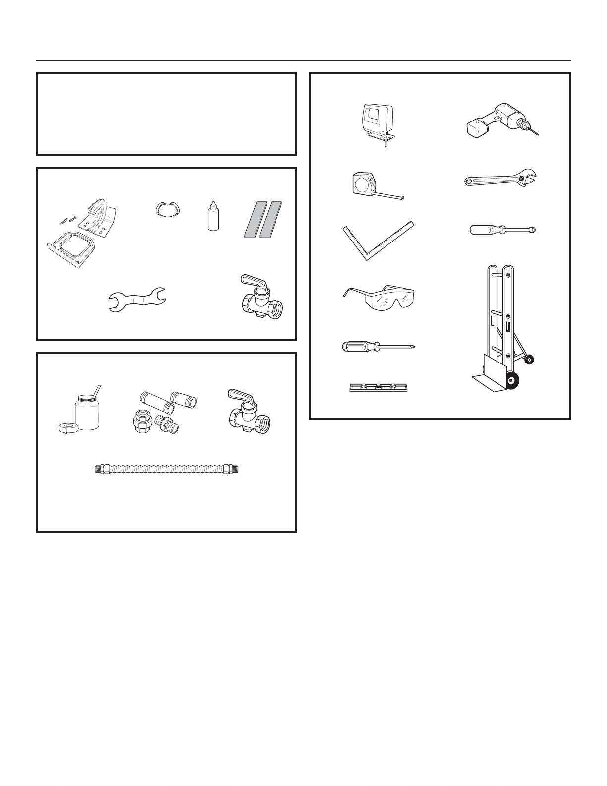
When installing a gas appliance the use of
ROGIOH[LEOHFRQQHFWRUVFDQFDXVHJDVOHDNVDQG
SHUVRQDOLQMXU\$OZD\VXVHD1(:IOH[LEOHFRQQHFWRU
Leak testing of the appliance shall be conducted
according to the manufacturer instructions.
The range must be electrically grounded in accordance
ZLWKORFDOFRGHVRULQWKHDEVHQFHRIORFDOFRGHVLQ
DFFRUGDQFHZLWKWKH1DWLRQDO(OHFWULFDO&RGH$16,
1)3$ODWHVWHGLWLRQ,Q&DQDGDHOHFWULFDOJURXQGLQJ
must be in accordance with the current CSA C22.1
&DQDGLDQ(OHFWULFDO&RGH3DUWDQGRUORFDOFRGHV6HH
Electrical Connections in this section.
Do not install this product with an air curtain hood or
other range hood that operates by blowing air down on
the cooktop. This airflow may interfere with operation of
WKHJDVEXUQHUVUHVXOWLQJLQILUHRUH[SORVLRQKD]DUG
FOR YOUR SAFETY
If you did not receive an anti-tip bracket with your
SXUFKDVHFRQWDFWXVDWcafeappliances.com to
receive one at no cost.
,Q&DQDGDcafeappliances.ca.)
)RULQVWDOODWLRQLQVWUXFWLRQVRIWKHEUDFNHWYLVLW
cafeappliances.com,Q&DQDGDcafeappliances.ca.)
WARNING %HIRUHEHJLQQLQJWKHLQVWDOODWLRQ
switch power off at service panel and lock the service
disconnecting means to prevent power from being
switched on accidentally. When the service disconnecting
PHDQVFDQQRWEHORFNHGVHFXUHO\IDVWHQDSURPLQHQW
ZDUQLQJGHYLFHVXFKDVDWDJWRWKHVHUYLFHSDQHO
Have a question or need assistance with your appliance? Try the Caféwebsite 24 hours a day, any day of the
year! You can also shop for more great Caféproducts and take advantage of all our on-line support services
designed for your convenience. In the US: cafeappliances.com. (In Canada, cafeappliances.ca.)
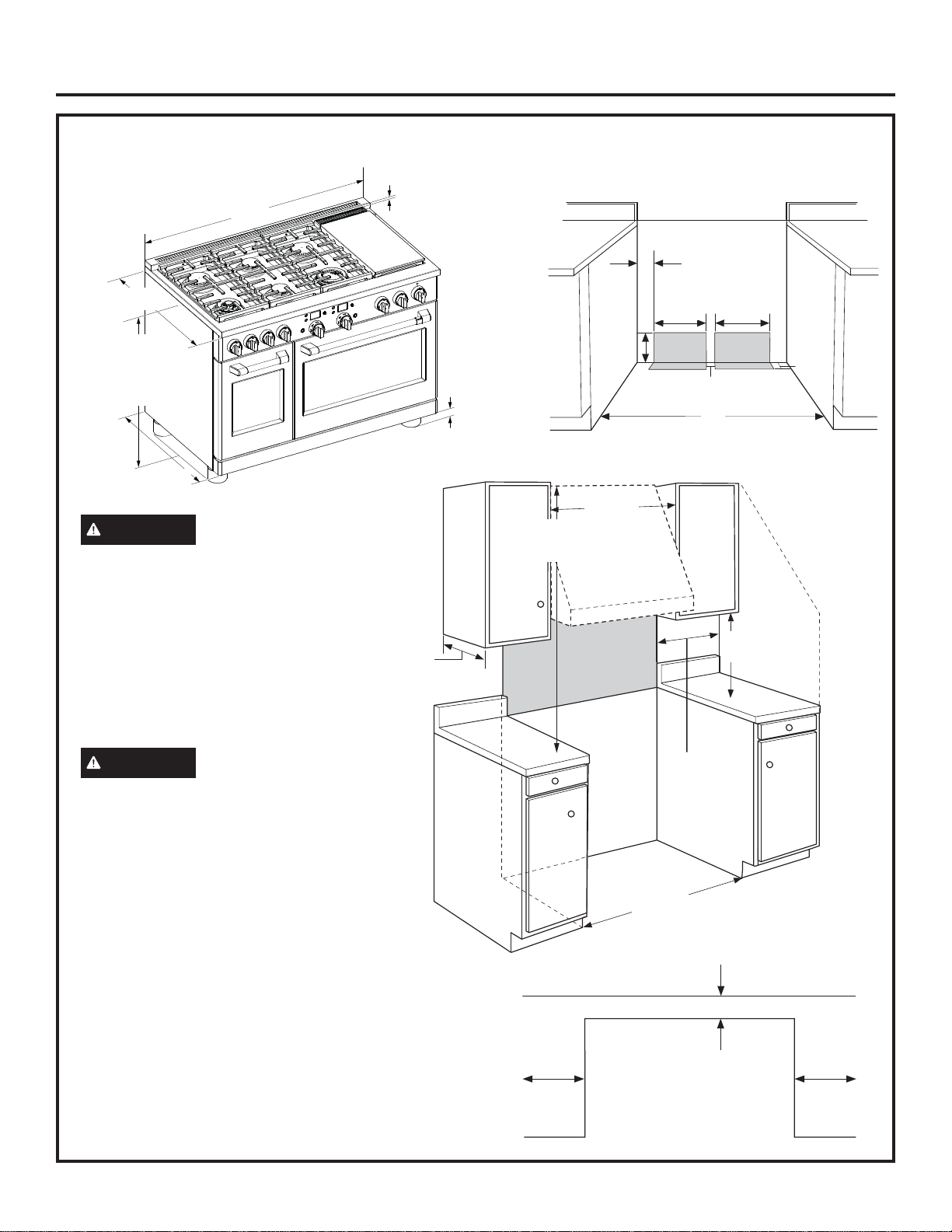
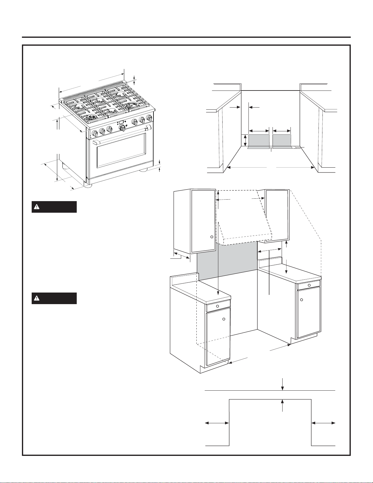
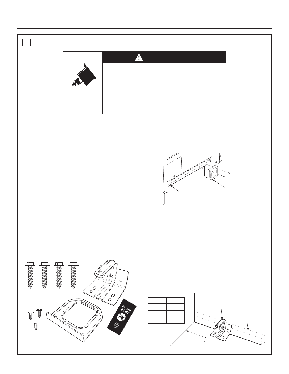
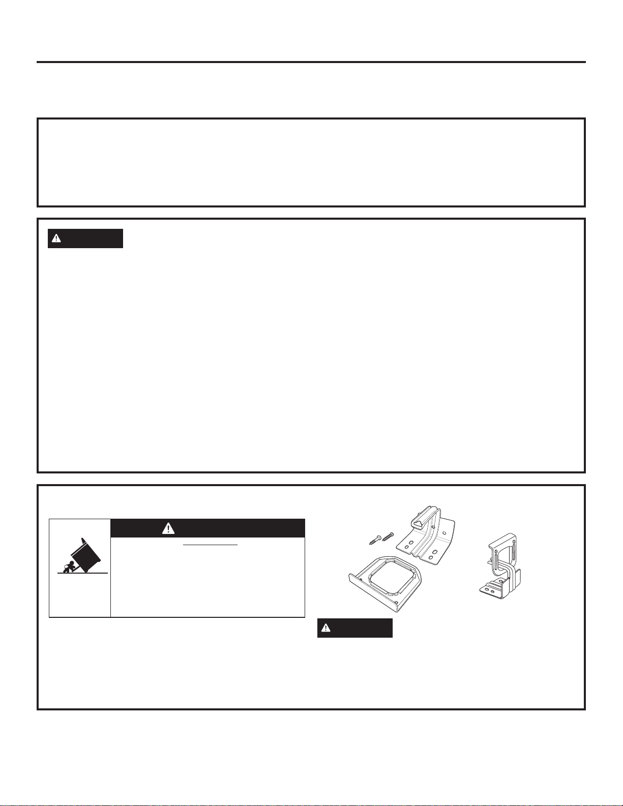
• A child or adult can tip the range and be killed.
• Install the anti-tip bracket to the wall or floor.
• Engage the range to the anti-tip bracket by sliding the
range back such that the foot is engaged.
• Re-engage the anti-tip bracket if the range is moved.
• Failure to do so can result in death or serious burns
to children or adults.
Tip-Over Hazard
WARNING
Anti-Tip Bracket
Kit Included
Rear View