Cafe CGY366 User manual

36” All Gas Professional Ranges
CGY366
31-2000814 Rev. 1 12-20 GEA
Questions? Visit cafeappliances.com.
Installation Instructions
TM
Contents
Safety Information ..................................2
Design Information
Product Dimensions and Clearances................4
Installation Information
High Altitude Kit ................................6
Materials Provided ..............................6
Materials Required (not provided) ..................6
Tools Required.................................6
Installation
Remove Packaging ............................7
Move the Range Indoors ........................8
Install Anti-Tip Device ..........................9
Converting to Propane (LP) Gas or Converting
Back to Natural Gas From Propane (LP) .........10
Gas Supply..................................10
Electrical Connections .........................11
Roll Range into Position........................11
Level the Range..............................12
Replace Oven Door(s).........................12
CheckBurners...............................13
CheckSurfaceBurners........................13
Finalize Installation............................13
When All Hookups Are Completed ...............13
Accessory Installation
Toekick.....................................14
UX12BS36PSS Accessory Installation
Optional Accessories—12” High Backsplash
Tools and Materials Required ...................15
Install 12” Backsplash .........................15
UXADBS36PSS Accessory Installation
Accessories—30” To 36” Adjustable Backsplash
Tools and Materials Required ...................16
Install the Wall Support Panels ..................16
Install Cover Panels...........................17
English • Français • Español

231-2000814 Rev. 1
Safety Information
READ AND SAVE THESE INSTRUCTIONS
IN THE COMMONWEALTH OF MASSACHUSETTS
ŶThis product must be installed by a licensed plumber
or gas fitter.
Ŷ :KHQXVLQJEDOOW\SHJDVVKXWRIIYDOYHVWKH\VKDOO
be the T-handle type.
Ŷ $IOH[LEOHJDVFRQQHFWRUZKHQXVHGPXVWQRWH[FHHG
5 feet.
WARNING FIRE OR EXPLOSION HAZARD
,IWKHLQIRUPDWLRQLQWKLVPDQXDOLVQRWIROORZHGH[DFWO\
DILUHRUH[SORVLRQPD\UHVXOWFDXVLQJSURSHUW\GDPDJH
personal injury or death.
Installation must be performed by a qualified installer.
Read these instructions completely and carefully.
,QVWDOODWLRQRIWKLVUDQJHPXVWFRQIRUPZLWKORFDOFRGHV
RULQWKHDEVHQFHRIORFDOFRGHVZLWKWKH1DWLRQDO
)XHO*DV&RGH$16,=1)3$ODWHVWHGLWLRQ
,Q&DQDGDLQVWDOODWLRQPXVWFRQIRUPZLWKWKHFXUUHQW
1DWXUDO*DV,QVWDOODWLRQ&RGH&$1&*$%RU
WKHFXUUHQW3URSDQH/3,QVWDOODWLRQ&RGH&$1&*$
%DQGZLWKORFDOFRGHVZKHUHDSSOLFDEOH7KLV
range has been design-certified by CSA International
DFFRUGLQJWR$16,=ODWHVWHGLWLRQDQG&DQDGLDQ
*DV$VVRFLDWLRQDFFRUGLQJWR&$1&*$ODWHVW
edition.
When installing a gas appliance the use of
ROGIOH[LEOHFRQQHFWRUVFDQFDXVHJDVOHDNVDQG
SHUVRQDOLQMXU\$OZD\VXVHD1(:IOH[LEOHFRQQHFWRU
Leak testing of the appliance shall be conducted
according to the manufacturer instructions.
The range must be electrically grounded in accordance
ZLWKORFDOFRGHVRULQWKHDEVHQFHRIORFDOFRGHVLQ
DFFRUGDQFHZLWKWKH1DWLRQDO(OHFWULFDO&RGH$16,
1)3$ODWHVWHGLWLRQ,Q&DQDGDHOHFWULFDOJURXQGLQJ
PXVWEHLQDFFRUGDQFHZLWKWKHFXUUHQW&6$&
&DQDGLDQ(OHFWULFDO&RGH3DUWDQGRUORFDOFRGHV6HH
Electrical Connections in this section.
'RQRWLQVWDOOWKLVSURGXFWZLWKDQDLUFXUWDLQKRRGRU
RWKHUUDQJHKRRGWKDWRSHUDWHVE\EORZLQJDLUGRZQRQ
WKHFRRNWRS7KLVDLUIORZPD\LQWHUIHUHZLWKRSHUDWLRQRI
WKHJDVEXUQHUVUHVXOWLQJLQILUHRUH[SORVLRQKD]DUG
FOR YOUR SAFETY
,I\RXGLGQRWUHFHLYHDQDQWLWLSEUDFNHWZLWK\RXU
SXUFKDVHFRQWDFWXVDWcafeappliances.com to
receive one at no cost.
,Q&DQDGDcafeappliances.ca.)
)RULQVWDOODWLRQLQVWUXFWLRQVRIWKHEUDFNHWYLVLW
cafeappliances.com,Q&DQDGDcafeappliances.ca.)
WARNING %HIRUHEHJLQQLQJWKHLQVWDOODWLRQ
VZLWFKSRZHURIIDWVHUYLFHSDQHODQGORFNWKHVHUYLFH
GLVFRQQHFWLQJPHDQVWRSUHYHQWSRZHUIURPEHLQJ
VZLWFKHGRQDFFLGHQWDOO\:KHQWKHVHUYLFHGLVFRQQHFWLQJ
PHDQVFDQQRWEHORFNHGVHFXUHO\IDVWHQDSURPLQHQW
ZDUQLQJGHYLFHVXFKDVDWDJWRWKHVHUYLFHSDQHO
Have a question or need assistance with your appliance? Try the Caféwebsite 24 hours a day, any day of the
year! You can also shop for more great Caféproducts and take advantage of all our on-line support services
designed for your convenience. In the US: cafeappliances.com. (In Canada, cafeappliances.ca.)
• A child or adult can tip the range and be killed.
• Install the anti-tip bracket to the wall or floor.
• Engage the range to the anti-tip bracket by sliding the
range back such that the foot is engaged.
• Re-engage the anti-tip bracket if the range is moved.
• Failure to do so can result in death or serious burns
to children or adults.
Tip-Over Hazard
WARNING
Anti-Tip Bracket
Kit Included
5HDU9LHZ

31-2000814 Rev. 1 3
Safety Information
READ AND SAVE THESE INSTRUCTIONS
BEFORE YOU BEGIN
Read these instructions completely and carefully.
ŶIMPORTANT— Save these instructions
for local inspector’s use.
ŶIMPORTANT— Observe all governing
codes and ordinances.
ŶIMPORTANT— Remove all packing
material and literature from oven before connecting
gas and electrical supply to range.
ŶIMPORTANT— To avoid damage to
\RXUFDELQHWVFKHFNZLWK\RXUEXLOGHURUFDELQHW
VXSSOLHUWRPDNHVXUHWKDWWKHPDWHULDOVXVHGZLOO
QRWGLVFRORUGHODPLQDWHRUVXVWDLQRWKHUGDPDJH
7KLVRYHQKDVEHHQGHVLJQHGLQDFFRUGDQFHZLWK
the requirements of UL and CSA International and
FRPSOLHVZLWKWKHPD[LPXPDOORZDEOHZRRGFDELQHW
temperatures of 194°F (90°C).
ŶNote to Installer — Be sure to leave these
LQVWUXFWLRQVZLWKWKHFRQVXPHU
ŶNote to Consumer —.HHSWKHVHLQVWUXFWLRQVZLWK
\RXU2ZQHU¶V0DQXDOIRUIXWXUHUHIHUHQFH
ŶServicer — The electrical diagram is in an envelope
attached to the back of the range.
ŶProper installation is the responsibility of the
installer.
ŶProduct failure due to improper installation is not
FRYHUHGXQGHUZDUUDQW\
ŶBefore installing your range on linoleum or any other
V\QWKHWLFIORRUFRYHULQJPDNHVXUHWKHIORRUFRYHULQJ
FDQZLWKVWDQG)ZLWKRXWVKULQNLQJZDUSLQJRU
discoloring. Do not install the range over carpeting
XQOHVVDVKHHWRI´WKLFNSO\ZRRGRUVLPLODU
LQVXODWRULVSODFHGEHWZHHQWKHUDQJHDQGFDUSHWLQJ
ŶFor Café3DUWVDQG$FFHVVRULHVYLVLWRXUZHEVLWHDW
cafeappliances.com
Ŷ,I\RXUHFHLYHGDGDPDJHGUDQJH\RXVKRXOG
contact your dealer.
IF SOLD OUTSIDE THE U.S. AND
CANADA
WARNING ,I\RXZLVKWRXVHWKLVSURGXFWZLWK
Liquefied Petroleum (LP) gas containing greater than
EXWDQH\RXPXVWSXUFKDVHWKH+$3URSDQH
FRQYHUVLRQDFFHVVRU\NLW&;%8357RRUGHU
please call 1.888.664.8403 or 1.787.276.4051. Failure
WRGRVRPD\UHVXOWLQFDUERQPRQR[LGHRUILUHKD]DUG
VENT HOOD COMBINATIONS
A suitable overhead vent hood is required for models
ZLWKDJULOODQGLVUHFRPPHQGHGIRUDOORWKHUPRGHOV
'XHWRWKHKLJKKHDWFDSDFLW\RIWKLVXQLWSDUWLFXODU
DWWHQWLRQVKRXOGEHSDLGWRWKHKRRGDQGGXFWZRUN
installation to assure it meets local building codes.
&OHDUDQFHVWRKRUL]RQWDOVXUIDFHVDERYHWKHUDQJH
PHDVXUHGWRWKHFRRNLQJVXUIDFHDUHEHORZ)DLOXUHWR
comply may result in fire hazard.
Ŷ,QVWDOODWLRQVZLWKRXWDKRRGUHTXLUH´PLQLPXPWR
combustibles.
Ŷ$FXVWRPKRRGLQVWDOODWLRQZLWKH[SRVHGKRUL]RQWDO
combustibles surfaces must have an Auto-On feature.
Ŷ)RURWKHULQVWDOODWLRQVZLWKDKRRGUHIHUWRKRRG
installation instructions for specific hood clearances.
CAUTION 7KHVHUDQJHVZHLJKXSWR
SRXQGV6RPHGLVDVVHPEO\ZLOOUHGXFHWKHZHLJKW
FRQVLGHUDEO\'XHWRWKHZHLJKWDQGVL]HRIWKHUDQJH
and to reduce the risk of personal injury or damage to
WKHSURGXFW
TWO PEOPLE ARE REQUIRED FOR PROPER
INSTALLATION.
Rating Label Location Rating Label Location

431-2000814 Rev. 1
Design Information
PRODUCT DIMENSIONS AND CLEARANCES
16”
0D[
36” Min.
12” Minimum
to Adjacent Wall
Non-
Combustible
Material **
60” Minimum
to Combustibles
36” Minimum
18”
Min.
3” Min. 3” Min.
Island
Cutout
7RS9LHZ
´0LQ
WARNING
,QVWDOODWLRQVZLWKRXWD
hood require 60” minimum to combustibles.
$FXVWRPKRRGLQVWDOODWLRQZLWKH[SRVHG
horizontal combustible surfaces must have
an Auto-On feature. Refer to hood installation
instructions for specific hood clearances.
7KHVXUIDFHRIWKHHQWLUHEDFNZDOODERYH
WKHUDQJHDQGEHORZWKHKRRGPXVWEH
FRYHUHGZLWKDQRQFRPEXVWLEOHPDWHULDO
VXFKDVPHWDOFHUDPLFWLOHEULFNPDUEOHRU
other stone.
CAUTION To prevent drafts from
DIIHFWLQJEXUQHURSHUDWLRQVHDODOORSHQLQJV
in floor under appliance and behind
DSSOLDQFHZDOO
** As defined in the National Fuel Gas Code (ANSI
=&6$%&XUUHQW(GLWLRQ&OHDUDQFHV
from non-combustible materials are not part of the
$16,=&6$VFRSHDQGDUHQRWFHUWLILHGE\
CSA. Clearances less than 12” must be approved by
ORFDOFRGHVDQGRUWKHDXWKRULW\KDYLQJMXULVGLFWLRQ
ADDITIONAL CLEARANCES:
$OORZ´PLQLPXPFOHDUDQFHWRDQDGMDFHQWZDOORQ
each side.
Working areas adjacent to the rangetop should have
´PLQLPXPFOHDUDQFHEHWZHHQFRXQWHUWRSDQGWKH
ERWWRPRIWKHZDOOFDELQHW
)RULVODQGLQVWDOODWLRQPDLQWDLQLQPLQLPXPIURP
cutout to back edge of countertop and 3 in. minimum
IURPFXWRXWWRVLGHHGJHVRIFRXQWHUWRSVHHWRSYLHZ
12”
Minimum
Each Side
Back
36”
´
´ 14”
*DV
Electric ´
2”
3”
Universal Utility Locations
´
Width 1” Countertop
to Cooking
Surface
´WR´
Height to trim.
Trim to be flush
or higher than
countertop.
´'HSWKWR
Front of Bullnose
´'HSWK
to Front of Door
7RHNLFN
leg Height
´
WR´

31-2000814 Rev. 1 5
Design Information
PRODUCT DIMENSIONS AND CLEARANCES
12” Min. to combustibles or 0”
to a non-combustible material
above the cooking surface **
´
With Oven Door Open
´
To Front of Handle
´
to
´
30-36”
12”
´
´
´
To Front Edge
´
To Front of Door
Optional
Backsplash
Accessories
0” Clearance
to a back or
VLGHZDOOEHORZ
the cooking
surface
7” Control Panel
Height
´
$VGHILQHGLQWKH1DWLRQDO)XHO*DV&RGH$16,=&6$%&XUUHQW(GLWLRQ&OHDUDQFHVIURP
QRQFRPEXVWLEOHPDWHULDOVDUHQRWSDUWRIWKH$16,=&6$VFRSHDQGDUHQRWFHUWLILHGE\&6$
&OHDUDQFHVOHVVWKDQ´PXVWEHDSSURYHGE\ORFDOFRGHVDQGRUWKHDXWKRULW\KDYLQJMXULVGLFWLRQ
WARNING The 12” high stainless steel backsplash accessory must be
LQVWDOOHGLQFRPELQDWLRQZLWKDFXVWRPQRQFRPEXVWLEOHEDFNVSODVK
7KHILQLVKHGEDFNVSODVKPXVWFRYHUWKHHQWLUHEDFNZDOOXSWRWKHERWWRPRIDKRRG
RUZKHQWKHUHLVQRKRRG´WRFRPEXVWLEOHV
12” high stainless steel backsplash accessory is only available for the 36” model)

631-2000814 Rev. 1
Installation Information
TOOLS REQUIRED
MATERIALS REQUIRED (not provided)
INSTALLATION AT HIGH ALTITUDE
2YHUIWSURGXFWFRQILJXUHGIRUQDWXUDOJDVRU
propane requires installation of kit (WB28X39728
for natural gas and WB28X39729 for propane gas).
)ROORZWKHLQVWUXFWLRQVLQFOXGHGZLWKWKHNLW
MATERIALS PROVIDED
Oven Rack
Lubricant Runners
(to protect
flooring)
´3LSH
(OERZ
Anti-Tip
%UDFNHW%UDFH
DQG6FUHZV
Leveling Leg
Wrench
Adjustable Wrench
´'ULYHURU:UHQFK
Safety Glasses
Drill and
Appropriate Bits
Measuring Tape
3KLOOLSV6FUHZGULYHU
6DEHU6DZ
Carpenter’s Square
Level Hand Truck
Shut-Off Valve
Shut-Off Valve
Pipe Fittings
IRRWPD[LPXPOHQJWK´2'&6$
DSSURYHGIOH[LEOHPHWDOJDVVXSSO\
NOTE:3XUFKDVHQHZIOH[LEOHOLQHGRQRW
XVHSUHYLRXVO\XVHGIOH[LEOHJDVOLQH
Pipe Thread
Sealant

31-2000814 Rev. 1 7
Installation
1REMOVE PACKAGING
CAUTION Stand clear. The ends of the cut metal
EDQGLQJPD\VQDSWRZDUG\RX
Ŷ&XWWKHPHWDOEDQGLQJ/LIWWKHFDUWRQVWUDLJKWXS
Ŷ/RFDWHWKHWZRUXQQHUVWULSVIURPWKHWRSRIWKH
SDFNDJLQJ7KHVHVWULSVZLOOEHXVHGWRSURWHFWWKH
kitchen floor during installation.
Ŷ5HPRYHFRUQHUSRVWV'LVSRVHRISDFNDJLQJPDWHULDOV
Ŷ5HPRYHJULOOJULGGOHFRYHUVJULOOJUDWHDQGEXUQHUJUDWHV
Ŷ/LIWRIIEXUQHUFDSVDQGUHPRYHIRDPSDGWKHQOLIWRII
burner heads and remove foam pad.
Ŷ2SHQRYHQGRRUVDQGUHPRYHSDFNDJLQJ5HPRYH
VKHOIKROGLQJEURLOHUSDQWDSHOLWHUDWXUHSDFNDJHVKHOI
lubricant and probe.
CAUTION 'RRUVDQGSDVVDJHZD\VOHDGLQJWRWKH
installation location require at least 32” opening. If the
RSHQLQJLVOHVVWKDQ´WKHRYHQGRRUVDQGFRQWURO
knobs must be removed.
REMOVE THE OVEN DOOR(S) ONLY IF NECESSARY
WRPRYHWKHUDQJHWKURXJKWKHGRRUZD\V7RSUHYHQW
GDPDJHWRWKHVLGHVRIWKHUDQJHLWZLOOEHQHFHVVDU\WR
pad the corners beneath the straps on the hand-truck.
To remove the oven door(s):
Ŷ7RUHPRYHWKHRYHQGRRUV
Ŷ)XOO\RSHQWKHGRRU
Ŷ(DFKKLQJHKDVDKLQJHORFN3XOOWKHKLQJH
Ŷ)LUPO\JUDVSWKHGRRUDWWKHWRSVLGHV
Ŷ&ORVHWKHGRRUWRWKHQHDUYHUWLFDOSRVLWLRQ
Ŷ/LIWWKHGRRUXSDQGSXOOVWUDLJKWRXW
Remove Foam Pads
Hinge
Lock

831-2000814 Rev. 1
Installation
2MOVE THE RANGE INDOORS
7LOWWKHUDQJHIRUZDUGRQWKHVNLG
2. Lift the toekick out of the foam base.
3. Drive the blade of the hand-truck beneath the foam
block.
IMPORTANT:'RQRWUHPRYHWKHEDVHIRDPEORFNZKLOH
the hand-truck is in use. Place the hand-truck blade
underneath the base foam block and transport the range
to the final location.
4. Attach the hand-truck straps around the unit.
IMPORTANT:3ODFHWKHKDQGWUXFNVWUDSVEHORZWKH
RYHQGRRUKDQGOHV7RDYRLGGDPDJLQJWKHVLGHSDQHOV
SODFHDSDGEHWZHHQWKHKDQGWUXFNDQGWKHUDQJH
7LOWWKHUDQJHWRORZHUWKHKDQGWUXFNZKHHOVRIIWKH
skid.
6. Place the appliance runners on the floor at the left
and right sides in front of the opening.
IMPORTANT: The runners provide a surface for
UROOLQJWKHUDQJHLQWRWKHILQDOSRVLWLRQDQGZLOOSURWHFW
the floor finish. The runners must be removed before
leveling the range.
7. Move the range indoors. Position the range in front of
WKHLQVWDOODWLRQORFDWLRQRQWRWKHUXQQHUV
Toekick
Toekick
Insert Blade Under
the Foam Block
You may need to remove
the front of the foam block
WRILWWKURXJKWKHGRRUZD\
Hand-Truck
6WUDSV%HORZ
Oven Door
Handles
Range
Opening
Runners
for Rolling
the Range
into
Position

31-2000814 Rev. 1 9
Installation
3INSTALL ANTI-TIP DEVICE
7RUHGXFHWKHULVNRIWLSSLQJWKHUDQJHWKHUDQJHPXVW
be secured by a properly installed anti-tip bracket. See
LQVWDOODWLRQLQVWUXFWLRQVVKLSSHGZLWKWKHEUDFNHWIRU
complete details before attempting to install.
To check if the bracket is installed and engaged
SURSHUO\ORRNXQGHUQHDWKWKHUDQJH7KHDQWLWLSEUDFNHW
should be inserted into the opening on the anti-tip brace
on the range. If the bracket arm misses the brace to the
OHIWRUULJKWRUWKHEUDFNHWDUPLVQRWSURWUXGLQJWKURXJK
WKHEUDFHRSHQLQJWKHEUDFNHWPXVWEHUHLQVWDOOHG
,IWKHUDQJHLVSXOOHGIURPWKHZDOOIRUDQ\UHDVRQ
DOZD\VUHSHDWWKLVSURFHGXUHWRYHULI\WKHUDQJHLV
properly secured by the anti-tip bracket.
,I\RXUUDQJHKDVQRDQWLWLSEUDFNHWFDOO
to receive one at no cost.
,IWKHDQWLWLSGHYLFHVXSSOLHGZLWKWKHUDQJHGRHVQRW
ILWWKLVDSSOLFDWLRQXVHWKHXQLYHUVDO$QWL7LS'HYLFH
WB2X7909.
5HDGWKH$+$0$QWL7LS6DIHW\%URFKXUHSDFNHGZLWK
the bracket.
Anti-Tip Parts Provided
Ŷ$WWDFKWKHDQWLWLSEUDFHRQWRWKHERWWRPRIWKHUDQJH
LQWKHUHFHVVHGDUHD,QVWDOOKH[VFUHZVSURYLGHG
through the brace and into the range.
NOTE: This anti-tip device may be installed on the
opposite side of the range.
Ŷ0HDVXUHDQGPDUN'LPHQVLRQ$VHHWDEOHEHORZ
from the left (or right) side of the installation location.
,IWKHFRXQWHUWRSKDVDQRYHUKDQJDGGWKDWGLPHQVLRQ
to Dimension A.
Ŷ3ODFHWKHDQWLWLSEUDFNHWDJDLQVWWKHIORRUDQGEDFNZDOO
DWWKHPDUNHGORFDWLRQ0DUNVFUHZKROHVIRUIDVWHQLQJ
WKHEUDFNHWWRWKHZDOOVROHSODWHDQGWKHIORRU
Ŷ'ULOO´SLORWKROHVDWDDQJOH
Ŷ6HFXUHWKHEUDFNHWWRWKHZDOODQGRUIORRUZLWKDWOHDVW
ZRRGVFUHZVSURYLGHG
For Concrete or Cement Construction: You must use
DSSURSULDWHIDVWHQLQJKDUGZDUHQRWSURYLGHG
• A child or adult can tip the range and be killed.
• Install the anti-tip bracket to the wall or floor.
• Engage the range to the anti-tip bracket by sliding the
range back such that the foot is engaged.
• Re-engage the anti-tip bracket if the range is moved.
• Failure to do so can result in death or serious burns
to children or adults.
Tip-Over Hazard
WARNING
Anti-Tip Bracket
Anti-Tip Brace
:RRG6FUHZV
AHAM Anti-Tip
Safety Brochure
+H[+HDG6FUHZV
UHTXLUHGH[WUD
Alternate Brace
Position
+H[6FUHZV
Anti-Tip Brace
Anti-Tip Bracket
A
Wall Sole Plate
Range A
36” ´

10 31-2000814 Rev. 1
Installation
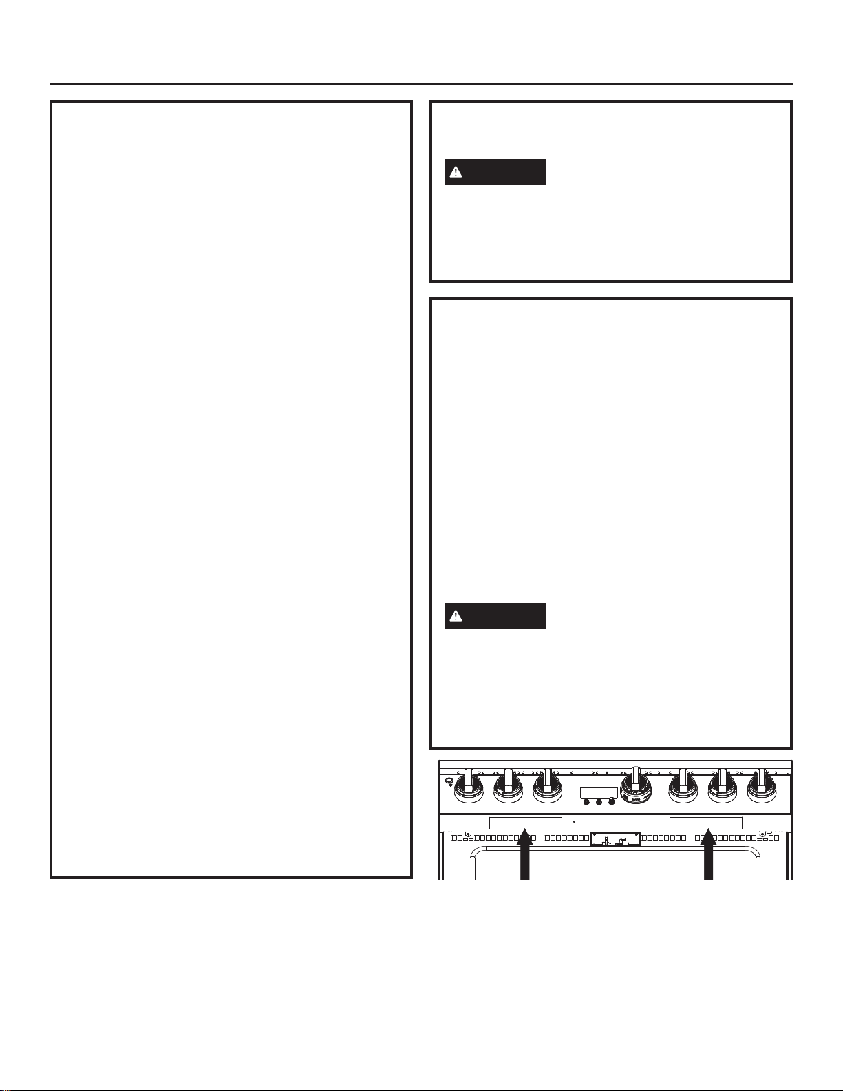
4CONVERTING TO PROPANE (LP)
GAS OR CONVERTING BACK
TO NATURAL GAS FROM
PROPANE (LP)
7KLVUDQJHOHDYHVWKHIDFWRU\VHWIRUXVHZLWKQDWXUDO
JDV,I\RXZDQWWRFRQYHUWWRSURSDQH/3JDVWKH
conversion must be performed by a qualified propane
(LP) gas installer.
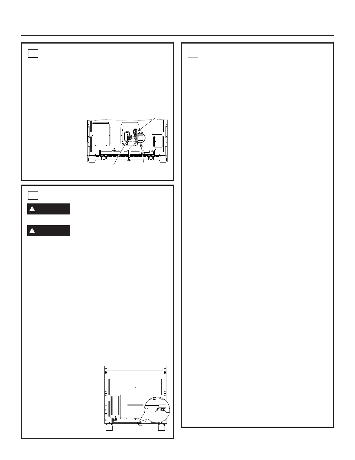
The conversion orifices
and instructions can
be found on back of
the range.
Keep these
instructions and all
orifices in case you
ZDQWWRFRQYHUWEDFN
to natural gas.
5GAS SUPPLY
WARNING )LUH+D]DUG'RQRWXVHDIODPHWR
check for gas leaks.
WARNING ([SORVLRQ+D]DUG'RQRWH[FHHG
IWOEVRIWRUTXHZKHQPDNLQJJDVOLQHFRQQHFWLRQV
Overtightening may damage the pressure regulator
UHVXOWLQJLQILUHRUH[SORVLRQKD]DUG
Gas Pressure Regulator
You must use the gas pressure regulator supplied
ZLWKWKLVUDQJH)RUSURSHURSHUDWLRQVWKHLQOHW
SUHVVXUHWRWKHUHJXODWRUVKRXOGEHDVIROORZV
Natural Gas:
0LQLPXPSUHVVXUH´RI:DWHU&ROXPQ
0D[LPXPSUHVVXUH´RI:DWHU&ROXPQ
Propane (LP) Gas:
0LQLPXPSUHVVXUH´RI:DWHU&ROXPQ
0D[LPXPSUHVVXUH´RI:DWHU&ROXPQ
If you are not sure about the inlet pressure contact
local gas supplier.
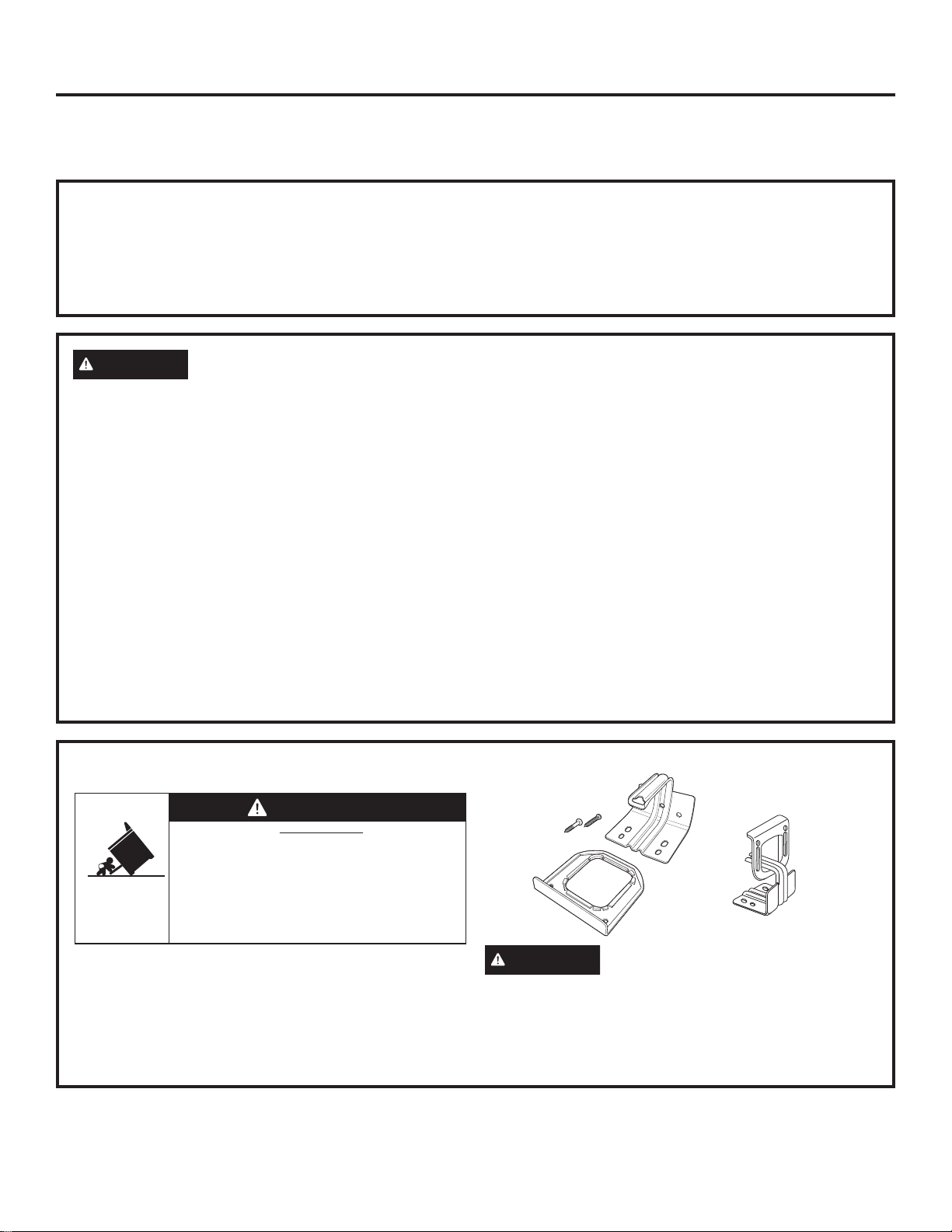
NOTE:$JDVVKXWRIIYDOYHLVVKLSSHGZLWKWKLVUDQJH
and should be installed at the rear of the range near
WKHIORRUZLWKWKHKDQGOH
IDFLQJGRZQZDUG7KLVVKXW
off valve is to be used in the
event that service is required.
7RDFFHVVWKHVKXWRIIYDOYH
remove the toe-kick panel
and reach under the range.
$QRSWLRQDO´HOERZLV
provided for connection to
the range gas inlet.
5GAS SUPPLY (cont.)
Shut off the main gas supply valve before
disconnecting the old range and leave it off until
the new hook-up has been completed. Don’t
forget to relight the pilot on other gas appliances
when you turn the gas back on.
%HFDXVHKDUGSLSLQJUHVWULFWVPRYHPHQWRIWKHUDQJH
WKHXVHRID&6$,QWHUQDWLRQDOFHUWLILHGIOH[LEOHPHWDO
appliance connector is recommended unless local
codes require a hard-piped connection.
,IWKHKDUGSLSLQJPHWKRGLVXVHG\RXPXVWFDUHIXOO\
DOLJQWKHSLSHWKHUDQJHFDQQRWEHPRYHGDIWHUWKH
connection is made.
7RSUHYHQWJDVOHDNVSXWSLSHWKUHDGVHDODQWRQRU
ZUDSSLSHWKUHDGWDSHZLWK7HIORQDURXQGDOOPDOH
H[WHUQDOSLSHWKUHDGV
A. Install a manual shut-off valve in the gas line in an
easily accessed location outside of the range. Make
VXUHHYHU\RQHRSHUDWLQJWKHUDQJHNQRZVZKHUH
DQGKRZWRVKXWRIIWKHJDVVXSSO\WRWKHUDQJH
% ,QVWDOOPDOH´IODUHXQLRQDGDSWHUWRWKH´
NPT internal thread at inlet of the shut-off valve on
WKHUDQJH8VHDEDFNXSZUHQFKRQWKHVKXWRII
valve to avoid damage.
& ,QVWDOOPDOH´RU´IODUHXQLRQDGDSWHUWRWKH
137LQWHUQDOWKUHDGRIWKHKRXVHVKXWRIIYDOYH
taking care to back-up the shut-off valve to keep it
from turning.
' &RQQHFWIOH[LEOHPHWDODSSOLDQFHFRQQHFWRUWRWKH
adapter on the range. Position range to permit
connection at the house shut-off valve.
( :KHQDOOFRQQHFWLRQVKDYHEHHQPDGHPDNHVXUH
all range controls are in the off position and turn
on the main gas supply valve. Use a liquid leak
detector at all gas connections to check for leaks
in the system.
:KHQXVLQJSUHVVXUHVJUHDWHUWKDQSVLJWR
SUHVVXUHWHVWWKHJDVVXSSO\V\VWHPRIWKHUHVLGHQFH
disconnect the range and individual shut-off valve
from the gas supply piping. When using pressures
RISVLJRUOHVVWRSUHVVXUHWHVWWKHJDVVXSSO\
V\VWHPVLPSO\LVRODWHWKHUDQJHIURPWKHJDVVXSSO\
system by closing the individual shut-off valve.
:KHQFKHFNLQJIRUSURSHURSHUDWLRQRIWKHUHJXODWRU
the inlet pressure must be at least 1” greater than the
operating (manifold) pressure as given on rating label
of product.
7HIORQ5HJLVWHUHGWUDGHPDUNRI'X3RQW
Gas Inlet
Oven
Regulator
Cooktop Regulator
Propane
Conversion Kit

31-2000814 Rev. 1 11
Installation
6ELECTRICAL CONNECTIONS
WARNING 6KRFN+D]DUG7KLVDSSOLDQFHPXVW
be properly grounded. Failure to do so can result in
electric shock.
(OHFWULFDO5HTXLUHPHQWVYROW+HUW]SURSHUO\
grounded dedicated circuit protected by a 15-amp or
20-amp circuit breaker or time delay fuse.
NOTE:8VHRIDXWRPDWLFZLUHOHVVRUZLUHGH[WHUQDO
VZLWFKHVWKDWVKXWRIISRZHUWRWKHDSSOLDQFHDUHQRW
recommended for this product.
Grounding
7KHSRZHUFRUGRIWKLVDSSOLDQFHLVHTXLSSHGZLWK
DWKUHHSURQJJURXQGLQJSOXJZKLFKSOXJVLQWRD
VWDQGDUGWKUHHSURQJJURXQGLQJZDOOUHFHSWDFOHWR
minimize the possibility of electric shock hazard from
this appliance.
7KHFXVWRPHUVKRXOGKDYHWKHZDOOUHFHSWDFOHDQG
circuit checked by a qualified electrician to make sure
the receptacle is properly grounded.
:KHUHDVWDQGDUGWZRSURQJZDOOUHFHSWDFOHLV
HQFRXQWHUHGLWLVWKHSHUVRQDOUHVSRQVLELOLW\DQG
REOLJDWLRQRIWKHFXVWRPHUWRKDYHLWUHSODFHGZLWKD
SURSHUO\JURXQGHGWKUHHSURQJZDOOUHFHSWDFOH
'212781'(5$1<&,5&8067$1&(6&8725
REMOVE THE THIRD (GROUND) PRONG FROM
THE POWER CORD. DO NOT USE AN ADAPTER.
DO NOT USE AN EXTENSION CORD.
Ground Fault Circuit Interrupters (GFCI’s) are not
required or recommended for gas range receptacles.
3HUIRUPDQFHRIWKHUDQJHZLOOQRWEHDIIHFWHGLI
operated on a GFCI-protected circuit but occasional
nuisance tripping of the GFCI breaker is possible.
7ROLL RANGE INTO POSITION
WARNING The Anti-Tip Bracket must be
properly installed to prevent tipping of the range.
Failure to do so can cause serious damage or injury.
Ŷ&KHFNWREHVXUHWKHDSSOLDQFHUXQQHUVDUH
EHQHDWKWKHZKHHOV
Ŷ7KHUDQJHLVVKLSSHGZLWKWKHZKHHOVLQWKHGRZQ
SRVLWLRQ&DUHIXOO\UROOWKHUDQJHLQWRSRVLWLRQEHLQJ
FDUHIXOQRWWRHQWDQJOHRUSLQFKWKHSRZHUFRUGDQG
IOH[LEOHJDVWXELQJ
Ŷ5HPRYHWKHUXQQHUVEHQHDWKWKHUDQJH
Ensure proper
JURXQGH[LVWV
before use
Be sure Anti-Tip
Bracket is engaged
ZLWKWKHEUDFHRQ
the range.

12 31-2000814 Rev. 1
Installation
8LEVEL THE RANGE
WARNING
The range must be level and be
VXSSRUWHGE\WKHOHJV²QRWWKHZKHHOV7KHUDQJHFRXOG
PRYHLIWKHZKHHOVPDNHFRQWDFWZLWKWKHIORRU%HVXUH
DOOOHJVPDNHFRQWDFWZLWKWKHIORRULQDQ\LQVWDOODWLRQ
Ŷ$OOOHJVPXVWEHOHYHOHGDIWHUWKHSURGXFWLVLQVWDOOHG
Ŷ&KHFNWREHVXUHWKHDGMRLQLQJFDELQHWVFRXQWHUWRSV
DUHOHYHOIURQWWREDFNDQGOHIWWRULJKWDFURVVWKH
opening of the range.
Ŷ
Measure the distance from the floor to the top of the
countertop in the left and right rear corners.
Ŷ
Adjust the height of the range to countertop height
or higher.
IMPORTANT:7KLVUDQJHVKRXOGDOZD\VEHLQVWDOOHG
at countertop height or higher. DO NOT INSTALL THE
RANGE LOWER THAN ADJACENT COUNTERTOP
+(,*+77KHUDQJHPXVWEHVXSSRUWHGE\DOOOHJV
regardless of countertop height.
FRONT LEG ADJUSTMENT
Ŷ$OHYHOLQJOHJZUHQFKLVVXSSOLHG5HDFKXQGHUWKH
front of the range near the right leg. Locate and
UHPRYHDWKXPEVFUHZWKHQVOLGHZUHQFKRXWRI
the slot.
Ŷ6OLGHIURQWF\OLQGHUVXSWRDFFHVVIURQWOHYHOLQJOHJV
Be careful not to damage cylinder.
Ŷ8VHWKHVXSSOLHGZUHQFKWRDGMXVWWKHIURQWOHYHOLQJ
OHJV7XUQFORFNZLVHWRH[WHQGWKHOHJVWROLIWDQG
VWDELOL]HWKHUDQJH7XUQFRXQWHUFORFNZLVHWRUHWUDFW
WKHOHJVDQGDOORZWKHUDQJHWRUHVWRQLWVUROOHUV
Ŷ%HVXUHWRUHWXUQWKHZUHQFKWRLWVVWRUDJHVORWIRU
future use.
8LEVEL THE RANGE (cont.)
REAR LEG ADJUSTMENT
WARNING To reduce the risk of fire or electric
VKRFNDOZD\VUHSODFHWKHVSLOOSOXJVLQWKHOHYHOLQJ
rod holes.
Ŷ
5HPRYHWZRVFUHZVIURPUHDUYHQWWULP6OLGHYHQW
WULPIRUZDUGWKHQOLIWXSWRUHPRYH
Ŷ
Remove the 2 spill plugs to locate the rear leg
H[WHQVLRQOHYHOLQJURGV8VHD´GULYHURUVRFNHW
ZUHQFKWRDGMXVWWKHOHIWRUULJKWUHDUOHJV
Ŷ
)LQGWKHWZRUHDUOHJH[WHQVLRQURGV8VHD´GULYHU
RUZUHQFKWRDGMXVWWKHOHIWRUULJKWUHDUOHJV
Ŷ
Replace the 2 spill plugs and then replace the rear
YHQWWULPXVLQJWKHRULJLQDOVFUHZV
9REPLACE OVEN DOOR(S)
Skip this step if oven doors are in place.
IMPORTANT: Do not lift the door by the handle.
To replace the oven doors:
Ŷ)LUPO\JUDVSWKHGRRUat the top sides. This is
critical.
Ŷ$SSURDFKWKHUDQJHZLWKWKHGRRUDQJOHGLQD
vertical position.
Ŷ*XLGHWKHKLQJHVLQWRWKHVORWV
Ŷ3XVKWKHGRRULQILUPO\ZKLOHRSHQLQJ
Ŷ2QFHLQSRVLWLRQRSHQWKHGRRUFRPSOHWHO\3XVK
WKHKLQJHORFNVEDFNLQWRZDUGWKHIURQWIUDPH
CAUTION 7DNHFDUHZKHQUHSODFLQJWKHRYHQ
doors. If the hinge latch
LVQRWVHFXUHO\ORFNHG
the hinge may snap back
and separate. If the hinge
VHSDUDWHV\RXPXVWDSSO\
SUHVVXUHSRVVLEO\ZLWK
your foot) to press it back
together and then engage
the hinge latch.
Spill Plugs Rear Leg
([WHQVLRQ
Rods
Slide leg
cylinder up.
7KXPE6FUHZ

31-2000814 Rev. 1 13
Installation
10 CHECK BURNERS
WARNING )LUHRU([SORVLRQ+D]DUG'RQRW
RSHUDWHWKHEXUQHUZLWKRXWDOOEXUQHUSDUWVLQSODFH
A. Burners - Place surface burners into corresponding
positions on cooktop.
B. Caps - Place caps on proper size burner.
C. Grates - The left and right grates are
interchangeable. Place the grates on the cooktop.
FINALIZE INSTALLATION
Place the burner grates over the burners. The grates
should be seated and should not rock.
WHEN ALL HOOKUPS ARE
COMPLETED
Make sure all controls are left in the off position. Make
VXUHWKHIORZRIFRPEXVWLRQDQGYHQWLODWLRQDLUWRWKH
range is unobstructed.
Check that all packing materials and tape have been
UHPRYHG7KLVZLOOLQFOXGHWDSHRQPHWDOSDQHOXQGHU
FRQWURONQREVLIDSSOLFDEOHDGKHVLYHWDSHZLUH
WLHVFDUGERDUGDQGSURWHFWLYHSODVWLF)DLOXUHWR
remove these materials could result in damage to the
appliance once the appliance has been turned on and
surfaces have heated.
11 CHECK SURFACE BURNERS
Push and turn a knob to the LITE position. A clicking
sound indicates proper operation of the ignition
V\VWHP:KHQOLJKWLQJDQ\EXUQHUVSDUNVZLOODSSHDU
DWDOOEXUQHUVEXWJDVIORZVIURPRQO\WKHRQHVHOHFWHG
2QFHDLULVSXUJHGIURPWKHVXSSO\OLQHEXUQHUVKRXOG
OLJKWZLWKLQVHFRQGV$IWHUEXUQHUOLJKWVURWDWHWKH
knob out of the LITE position. Try each burner in
succession until all burners have been checked.
Quality of Flames
Determine the quality of flames visually. Normal
burner flames should look like (A) or (B).
/RQJEULJKW\HOORZIODPHVDUHQRWQRUPDO1RUPDO
IODPHVPD\VKRZVLJQVRIDQRUDQJHWLQWZKHQZHOO
heated or signs of flickering orange due to particles in
the gas or air.
(A) Soft blue flames—
Normal for natural gas
(B) Yellow tips on
outer cones—
Normal for propane (LP) gas
Burner Cap Not Properly Seated
Burner Cap Properly Seated

14 31-2000814 Rev. 1
Accessory Installation
TOEKICK
Ŷ,QVWDOOWKHWRHNLFNDIWHUWKHUDQJHKDVEHHQOHYHOHG
Ŷ0HDVXUHWKHGLVWDQFHEHWZHHQWKHIORRUDQGWKH
bottom of range.
Ŷ/RRVHQWKHWZRVFUHZVRQHDFKHQG$GMXVWWKH
WRHNLFNKHLJKWE\VOLGLQJWKHXSSHUDQGORZHUSLHFHV
DSDUWWR´OHVVWKDQWKHPHDVXUHGKHLJKW
Ŷ6HFXUHWKHWRSDQGERWWRPVHFWLRQVE\WLJKWHQLQJWKH
VFUHZVRQHDFKHQG
Ŷ3XVKWRHNLFNDJDLQVWUDQJHOHJXQWLOFOLSVQDSVWROHJV
NOTE: Be sure the toekick snaps securely to the leg.
Bottom
of Toekick 6FUHZ
Top of
Toekick
Push
Push

31-2000814 Rev. 1 15
OPTIONAL ACCESSORIES—12” HIGH BACKSPLASH
UX12BS36PSS Accessory Installation
This kit provides for the installation of a 12” high
backsplash for 36” Professional Ranges and Rangetops.
TOOLS AND MATERIALS REQUIRED
Ŷ*ORYHVWRSURWHFWDJDLQVWVKDUSHGJHV
Ŷ7DQG3KLOOLSV
VFUHZGULYHUV
Ŷ'ULOOZLWK´DQG
´ELWV
Ŷ6DIHW\JODVVHV
Ŷ/HYHO
Ŷ3HQFLO
This Kit Includes
Ŷ:DOOVXSSRUWSDQHO
Ŷ&RYHUSDQHO
Ŷ+DUGZDUHSDFNDJHZLWK
±6WDLQOHVV6WHHO7RU[
VHOIWDSSLQJVFUHZV
±3KLOOLSVSDQKHDGZRRG
VFUHZV
INSTALL 12” BACKSPLASH
WARNING This backsplash must be securely
IDVWHQHGWRWKHZDOO)DLOXUHWRGRVRFRXOGUHVXOWLQ
damage or personal injury.
Ŷ,QVWDOODQGOHYHOWKHUDQJHRUUDQJHWRSDQGWKH
range hood according to the installation instructions.
Ŷ5HPRYHWKHEDFNVSODVKSDFNDJLQJDQGSURWHFWLYH
film.
Ŷ8VHDOHYHOWRSHQFLODKRUL]RQWDOOLQHRQWKHZDOO´
DERYHWKHUDQJHRUUDQJHWRS7KH´JDSDOORZVWKH
FRYHUSDQHOWRRYHUODSWKHZDOOVXSSRUWSDQHO
Ŷ/RFDWHZDOOVWXGVRQHDFKVLGH:KHUHVWXGVDUHQRW
DYDLODEOHSODQWRXVHZDOODQFKRUVQRWSURYLGHG
Ŷ$OLJQWKHZDOOVXSSRUWSDQHORQWKHPDUNHG
horizontal line and centered left to right.
Ŷ7KHZDOOVXSSRUWSDQHOPXVWEHVHFXUHGWRWKHZDOO
DWDOOFRUQHUV8VHZRRGVFUHZVSURYLGHGRUZDOO
anchors (not provided) to secure the support panel
WRWKHZDOO
Ŷ3ODFHWKHFRYHUSDQHORYHUWKHZDOOVXSSRUWSDQHO
DQGVHFXUHZLWK7RU[VFUHZVSURYLGHG,QVWDOO
VFUHZVRQHDFKVLGH
Wall Support Panel
Cover Panel
+DUGZDUH
Package
,QVWDOO:RRG6FUHZV
Install T-15
6FUHZV
Wall
Support
Panel
Wall Support
Panel
Cover Panel
Center
$UURZ
´

16 31-2000814 Rev. 1
ACCESSORIES—30” TO 36” ADJUSTABLE BACKSPLASH (not included)
UXADBS36PSS Accessory Installation
Ŷ7KLVEDFNVSODVKDGMXVWVWRILWWKHVSDFHEHWZHHQ
WKHWRSRIWKHUDQJHDQGWKHERWWRPRIWKHKRRG
IURP´0LQWR´0D[KHLJKW
Ŷ0D[LPXPVKHOIORDGEHDULQJZHLJKWLVOEV
TOOLS AND MATERIALS REQUIRED
Ŷ*ORYHVWRSURWHFWDJDLQVWVKDUSHGJHV
Ŷ7DQG3KLOOLSVVFUHZGULYHUV
Ŷ'ULOOZLWK´DQG´ELWV
Ŷ6DIHW\JODVVHV
Ŷ/HYHO
Ŷ3HQFLO
This Kit Includes
Ŷ7RSZDOOVXSSRUW
Ŷ%RWWRPZDOOVXSSRUW
Ŷ7RSFRYHUZLWKVKHOI
Ŷ%RWWRPFRYHU
Ŷ+DUGZDUHSDFNDJHZLWK
±6WDLQOHVV6WHHO7RU[
VHOIWDSSLQJVFUHZV
±3KLOOLSVSDQKHDGZRRG
VFUHZV
– 3 Stainless Steel #2 truss head
VFUHZVIRUDOWHUQDWH
installation method)
INSTALL THE WALL SUPPORT PANELS
WARNING 7KHZDOOVXSSRUWSDQHOVPXVWEH
VHFXUHO\IDVWHQHGWRWKHZDOO)DLOXUHWRGRVRFRXOG
result in damage or personal injury.
IMPORTANT: This backsplash is designed to cover
WKHZDOOEHWZHHQWKHERWWRPRIWKHKRRGDQGWKHWRSRI
the range. The vent hood should be installed over the
rangetop or range before installing this backsplash.
Ŷ,QVWDOODQGOHYHOWKH5DQJH5DQJHWRSDFFRUGLQJWR
the product installation instructions.
Ŷ5HPRYHEDFNVSODVKSDFNDJLQJDQGSURWHFWLYHILOP
Ŷ/RFDWHZDOOVWXGVRQHDFKVLGH:KHUHVWXGVDUHQRW
DYDLODEOHSODQWRXVHZDOODQFKRUVQRWSURYLGHG
Ŷ8VHDOHYHOWRSHQFLOKRUL]RQWDOOLQHVRQWKHZDOO
RQH´EHORZWKHYHQWKRRGDQGWKHRWKHU´
DERYHWKH5DQJH5DQJHWRS7KLV´VSDFHDOORZV
WKHFRYHUSDQHOVWRRYHUODSWKHZDOOVXSSRUWV
Ŷ6HFXUHWKHWRSZDOOVXSSRUWSDQHOWRWKHZDOOZLWK
ZRRGVFUHZVWKURXJKWKHRXWHUPRVWVWXGV
Ŷ8VHZRRGVFUHZVWRVHFXUHWKHERWWRPZDOOVXSSRUW
panel. The center slot should be positioned at the top.
7KHJDSEHWZHHQWKHWRSDQGERWWRPVXSSRUWSDQHOV
ZLOOEHFRYHUHGE\WKHWRSFRYHUZLWKVKHOI
+DUGZDUH
Package
Top Cover
ZLWK6KHOI
Bottom Cover
Bottom Wall Support
Top Wall
Support
´
Secure the
top panel to
WKHZDOOZLWK
ZRRGVFUHZV
´
Secure the
bottom panel to
WKHZDOOZLWK
ZRRGVFUHZV
Wood
6FUHZV
Center
$UURZ
Wood
6FUHZV

31-2000814 Rev. 1 17
INSTALL COVER PANELS
See alternate method if side access is blocked.
Ŷ+ROGWKHERWWRPFRYHURYHUWKHERWWRPVXSSRUW
ZKLOHGULYLQJRQHVFUHZSURYLGHGLQWRHDFKVLGH
Ŷ3ODFHWKHWRSFRYHUZLWKVKHOIRYHUWKHWRSZDOO
VXSSRUW,I\RXKDYHDFFHVVWRWKHVLGHVVHFXUHWKH
SDQHOZLWKWZRVFUHZVRQHDFKVLGH
Ŷ6HFXUHWKHWRSFRYHUZLWKVKHOIWRWKHWRSVXSSRUW
ZLWKVFUHZVWKURXJKWKHIURQWRIWKHSDQHODWWKHWRS
FRUQHUV8VHRQHVFUHZRQHDFKVLGH
INSTALL COVER PANELS (cont.)
ALTERNATE METHOD: When side access is blocked
Ŷ,QVWDOOERWWRPFRYHURYHUWKHERWWRPVXSSRUWZKLOH
GULYLQJRQHVFUHZLQWRHDFKVLGH
Ŷ+ROGWRSFRYHULQSODFHZKLOHPDUNLQJVFUHZORFDWLRQV
MXVWEHORZVKHOIVXSSRUWDQGRQWRERWWRPFRYHU
Ŷ5HPRYHWKHVKHOIDQGGULOOD´GLDPHWHUKROHLQ
the pencil-marked locations.
Ŷ0RXQWWKHWRSFRYHURYHUWKHWRSVXSSRUWDQG
VHFXUHWKHIURQWFRYHUZLWKVFUHZVWKURXJKWKH
drilled holes on each side.
Ŷ,QVWDOOVFUHZVWKURXJKHDFKWRSFRUQHU
0DUN6FUHZ
Locations for
Alternate Method
ACCESSORIES—30” TO 36” ADJUSTABLE BACKSPLASH (not included) (Cont.)
UXADBS36PSS Accessory Installation
Install
6FUHZ
Cover Panel
Install
6FUHZ
,QVWDOO&RUQHU6FUHZV
,QVWDOO6FUHZ
on Each Side
Shelf
,QVWDOO6FUHZLQ7RS&RUQHURQ(DFK6LGH

18 31-2000814 Rev. 1
NOTE: :KLOHSHUIRUPLQJLQVWDOODWLRQVGHVFULEHGLQWKLVERRN
VDIHW\JODVVHVRUJRJJOHVVKRXOGEHZRUQ
NOTE: Product improvement is a continuing endeavor at
*($SSOLDQFHV7KHUHIRUHPDWHULDOVDSSHDUDQFHDQG
VSHFLILFDWLRQVDUHVXEMHFWWRFKDQJHZLWKRXWQRWLFH
3ULQWHGLQ0H[LFR
Other manuals for CGY366
2
Table of contents
Other Cafe Range manuals
Popular Range manuals by other brands

Whirlpool
Whirlpool YSF377PEGQ7 installation instructions

Bartscher
Bartscher 115.090 Instructions for installation, operation and maintenance

Kenmore
Kenmore 790.3668 Series Use & care guide

GE
GE JDP36 owner's manual

Indesit
Indesit K 342 G/R Installation & use

Maytag
Maytag 30" Freestanding Gas and Electric Ranges Service manual