Cairn OptoSplit II Operating instructions

Troubleshooting
OPTOSPLIT II
This document details common technical queries reported by OptoSplit II users, how to troubleshoot, when to contact
Cairn and the information we require to provide help quickly to allow your research to continue.
Please refer to the OptoSplit II manual for guidance on setup.
For guidance on the OptoSplit II Bypass unit, please refer to supplementary documentation.
Useful information
Below is general guidance for all image-splitter troubleshooting:
• Make a note of the OptoSplit serial number (found on the underside of the unit)
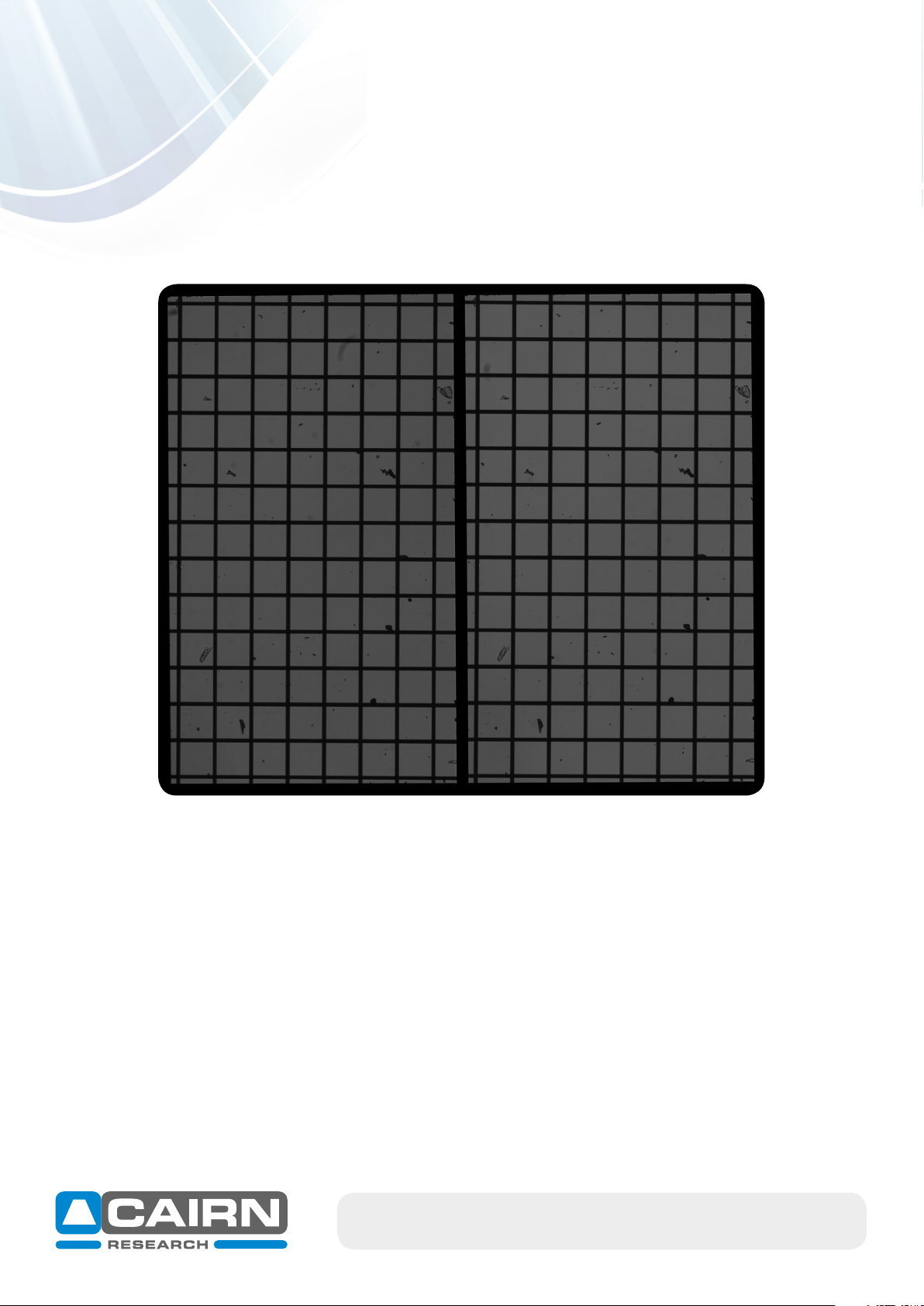
• Please save troubleshooting images as Tiff files as these contain the most information.
• Always save the raw data file (i.e. the non-overlaid dual channel images) rather than just the overlay.
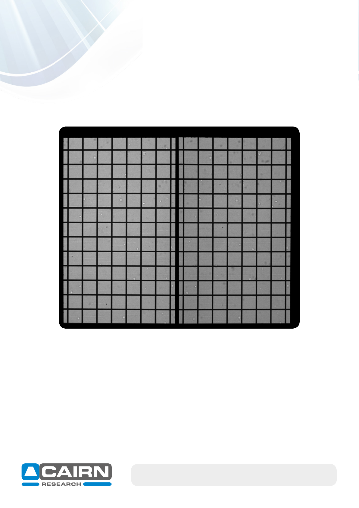
• Calibrate the unit (as per the set-up guide) and approach troubleshooting firstly with the calibration
cube supplied (consisting of a 50% / 50% mirror).
• Make a detailed note of your emission filters and dichroic mirror. This includes the wavelength and the
specification of the items.
• Please note: we strongly recommend 2mm thick ‘UltraFlat’ dichroic mirrors (UF2) from Chroma for
minimal distortion when using the OptoSplit:
https://www.cairn-research.co.uk/products/chroma-filters-beamsplitters/
As UK Chroma distributors, we are happy to provide filter advice from our in-house experts, so
please do not hesitate to get in touch (tech@cairn-research.co.uk)
• Please also let us know the model of the camera you are using and provide a photograph of the
OptoSplit in place on your microscope.
email: sales@cairn-research.co.uk tech@cairn-research.co.uk
+44(0)1795 590140 www.cairn-research.co.uk

email: sales@cairn-research.co.uk tech@cairn-research.co.uk
+44(0)1795 590140 www.cairn-research.co.uk
Common troubleshooting issues
1) Darker image on one side (vignetting)
Observations & likely cause
• Image appears darker on one side, known as vignetting
• Often observed when changing from split-mode to single-channel (bypass) mode due to
sub-optimal mirror positioning.
Resolution
• Locate the ‘Trim’ adjustment on the underside of the unit and loosen the clamp screw if required.
• Slide the Trim adjustment until both images are evenly illuminated.
• The Trim control can then be locked in place by re-tightening the clamp screw.

email: sales@cairn-research.co.uk tech@cairn-research.co.uk
+44(0)1795 590140 www.cairn-research.co.uk
2) Uneven Illumination on both images
Observations & likely cause
• Illumination is inconsistent over both images
• Often symptomatic of a poorly aligned light source which has not been setup for Köhler illumi-
nation, unrelated to the image splitter.
Resolution
• Remove the OptoSplit and optimise illumination settings on your microscope as per
manufacturers instructions.
• Once optimisation is complete, reattach the OptoSplit.

email: sales@cairn-research.co.uk tech@cairn-research.co.uk
+44(0)1795 590140 www.cairn-research.co.uk
3) Overlay of two images is poor
Observations & likely cause
• If the split control is turned the wrong way, image quality can be affected.
• Split control should always be turned ANTI-CLOCKWISE (i.e. this moves the two images apart)
for the best split results.
Resolution
• Identify which is the reflected (shorter wavelength) image by following the flow-chart below.
• Always turn the split control anti-clockwise to separate the two images when using a standard
OptoSplit II (please note, for the OptoSplit II bypass we recommend a clockwise split).

email: sales@cairn-research.co.uk tech@cairn-research.co.uk
+44(0)1795 590140 www.cairn-research.co.uk
Flowchart for confirming camera orientation is correct and images are split correctly

email: sales@cairn-research.co.uk tech@cairn-research.co.uk
+44(0)1795 590140 www.cairn-research.co.uk
4) Edges of the OptoSplit aperture appear rough
Observations & likely cause
• Rough, non-uniform feature in focus on diaphragm (aperture) blade
• Most likely cause is dirt (highly magnified) on the aperture blades
Resolution
• Carefully clean the aperture using a lint-free lens tissue

email: sales@cairn-research.co.uk tech@cairn-research.co.uk
+44(0)1795 590140 www.cairn-research.co.uk
5) Edges of the OptoSplit aperture are out of focus
Observations & likely cause
• Aperture edges out of focus in both images
• Magnification and distortion to one of the split images
• A fine focus adjustment is available on the OptoSplit output port closest to the camera (see
‘Focussing the Camera on the Aperture’ instructions below). This adjustment is required if,
when initially installed, the aperture blades are slightly out of focus due to the individual
position of the camera sensor. However, this adjustment is minimal and if over-adjusted,
causes significant image distortion, magnification of one image and blurring of the aperture
occurs.
• Often, the fine focus adjustment is incorrectly used to focus the sample image, or to focus the
camera image with the image observed via the eye-pieces (bifocality). Please only adjust the
fine focus if the aperture blades are out of focus and note any adjustment should be minimal.

email: sales@cairn-research.co.uk tech@cairn-research.co.uk
+44(0)1795 590140 www.cairn-research.co.uk
Resolution
• Please refer to the guidelines below: ‘Focussing the Camera on the Aperture’ to identify the
adjustment required. Please note the rotation of the focus ring required to bring the aperture
blades into fine focus is minimal as each unit is pre-set prior to shipping.
• It is best practice to adjust the focus ring whilst the sample image is out of focus; concentrate
only on bringing the aperture blades into focus. It may be useful to zoom in on one aperture
edge using your imaging software.
Focussing the Camera on the Aperture
If the Optosplit II aperture is not in sharp focus, then adjust the fine focus on the camera as follows:
• Set an aperture size of less than half the width of the camera frame.
• Loosen the two hex screws on the Focus ring
• Separate the two images slightly with the Split control.
• Loosen the C-mount hex screws.
• Adjust the focus by turning the focus ring whilst ensuring the optosplit is secure, and holding the
camera, until the aperture edges are in sharp focus.
• Then, lock off the focus ring by re-tightening the hex screws. Ensure the camera is again lined up
with its top orientated the same way as the top of the Optosplit II and then lock off the Camera
C-mount.
Focus ring
Hex screws
Camera C-mount
Split adjuster

email: sales@cairn-research.co.uk tech@cairn-research.co.uk
+44(0)1795 590140 www.cairn-research.co.uk
Observations & likely cause
• Two channels are non-parallel
• If the incorrect controls have been used to separate the two images, they appear non-parallel.
• when the two channels are superimposed, the only controls that will need adjusting are the
‘Split’ control and the aperture size.
• In the incorrect image below, V1 and V2 have been used to separate the two images in the
vertical axis.
• A quick way to identify this error is if the ‘V’ control moves an image horizontally, which
indicates the camera is in the incorrect orientation.
6) Two emission channels are non-parallel
Resolution
• Refer to the OptoSplit II Set up Guide to familiarise yourself with key controls and follow
‘Adjusting the Position of the Images’ to re-align the two channels.
• It is advisable to initially set up the two OptoSplit channels using the calibration cube included
as standard with your unit. This consists of a 50%/50% beam-splitter, therefore both images will
contain the same information and intensity.
• It is also advisable to refer to the ‘Flowchart for confirming camera orientation’ in section 3 of
this Troubleshooting Guide.

email: sales@cairn-research.co.uk tech@cairn-research.co.uk
+44(0)1795 590140 www.cairn-research.co.uk
7) The image quality on my sCMOS camera is poor, particularly on the edges
Observations & likely cause
• Poor image quality observed when using an older OptoSplit unit (generally pre 2013) with a
large sensor (sCMOS) camera, particularly in the image corners.
• In 2013 we introduced the ‘LS’ (Large Sensor) version of both the OptoSplit II and OptoSplit III
(Triplesplit) to accommodate larger camera sensors (up to 18.8 mm diagonal). These LS units
include longer focal length custom lenses to minimise image distortion and can be used with
any camera sensor size.
Resolution
• If you are unsure whether you have an LS OptoSplit (‘Large Sensor’ format), please contact us
with your serial number and we will consult our records. Generally, the LS units are identified by
their longer length in total: the ‘output tube’ length from the main OptoSplit body to the end of
the camera c-mount is ~100mm for an LS unit.
• Older OptoSplit II units can be upgraded to the LS format in the majority of cases. Please contact
us for a quotation.
• Overall the LS model gives improved image quality with all cameras, so an upgrade of all older
models may be worth considering.

email: sales@cairn-research.co.uk tech@cairn-research.co.uk
+44(0)1795 590140 www.cairn-research.co.uk
8) One channel is disproportionally brighter than the other
Observations & likely cause
• One channel disproportionally brighter than the other in split mode.
• Caused by differences in intensity of the emitted fluorophores.
Resolution
• The OptoSplit can be supplied with an additional Neutral Density
kit to reduce the intensity of the brightest channel.
• Four neutral density (ND) filters are routinely supplied, labelled
as follows:
03GN25: 50% Transmittance
05GN25: 32% Transmittance
06GN25: 25% Transmittance
10GN25: 10% Transmittance
• The ND filters are mounted in the auxiliary drop-in holders
provided with each kit. Auxiliary Drop-in

email: sales@cairn-research.co.uk tech@cairn-research.co.uk
+44(0)1795 590140 www.cairn-research.co.uk
9) One channel is slightly out of focus (chromatic aberration)
Observations & likely cause
• One channel is slightly out of focus compared to the other.
• Chromatic aberration results when the focal length changes depending upon the wavelength and
is predominantly introduced by the objective lens. When imaging two wavelengths simultaneously,
the phenomenon is observed using the OptoSplit II, rather than being caused by it.
Resolution
• The OptoSplit can be supplied with a Corrector Lens kit as an additional accessory.
• Three weak crown glass lenses are typically supplied, labelled as follows:
• IO137: Focal length 1346mm
• IO138: Focal length 2019mm
• IO139: Focal length 4034mm
• The corrector lenses are mounted in the auxiliary drop-in holders provided with each kit.
• Finding the correct lens is a process of trial and error. We recommend starting with the weakest
lens (IO139) in the out of focus channel.
• For further assistance on chromatic correction or multi-depth imaging, please contact us.
For all technical support, please contact our support team
tech@cairn-research.co.uk or call us on 01795 590 140
Other manuals for OptoSplit II
2
Table of contents
Other Cairn Cables And Connectors manuals