Cairn OptoSplit II User manual

+44(0)1795 590140 www.cairn-research.co.uk
Set up guide
OPTOSPLIT II

+44(0)1795 590140 www.cairn-research.co.uk
Set up guide
OPTOSPLIT II
This guide details initial set up and installation of your OptoSplit II image splitter.
Each unit is serial numbered, calibrated and QC’d prior to delivery, therefore minimal setup is required
providing you are familiar with the key controls. If you have any questions, please do not hesitate to get in
touch.
Before using the Optosplit II image splitter you will first need to install the appropriate set of filters and
beamsplitter for your application into the Cairn Filter Cube. A calibration cube with a 50% beamsplitter is
also provided for alignment or spectrally neutral applications.
C
A
I
R
N
www
.
c
a
i
r
n
-
r
e
s
e
a
r
c
h
.
c
o
.
u
k
C
A
I
R
N
www
.
c
a
i
r
n
-
r
e
s
e
a
r
c
h
.
c
o
.
u
k
C
A
I
R
N
www
.
c
a
i
r
n
-
r
e
s
e
a
r
c
h
.
c
o
.
u
k
Installing Filters into the Cairn Filter Cube
The Cairn Filter Cube has spaces for two 25mm filters. These are held in place by locking rings which can be re-
moved using the tool provided. To fit a filter, remove the locking ring and place the filter orientated so that the arrow
points into the Cairn Filter Cube and towards the beamsplitter (correct for Chroma mirrors, please refer to us if
using filters from a different manufacturer). Then simply replace and tighten the locking ring.
Installing Dichroic Mirrors into the Cairn Filter Cube
To fit your dichroic mirror into the Cairn Filter Cube remove each of the four screws that secure the two halves
together. You will then be able to gently pull the two halves apart. There is one steel locating rod in each half of the
cube to ensure the correct alignment when it is reassembled. Once the two halves of the cube are seperated, place
the dichroic mirror into the rectangular recess, active face down. Then simply reassemble the cube and tighten the
screws.
Remove the four screws and separate the two halves. Place the dichroic hold-
er in the recess and
place the spring on top.
Replace the top half and
resecure the screws.
Screws Screws
Turn the locking
ring anticlock-
wise to remove
Carefully place the
filter inside the
recess
Replace locking
ring and rotate
it clockwise to
secure
The arrow should
be orientated into
the filtercube and
towards the beam-
splitter
Reflected path
(short wavelength)
Transmitted path
(long wavelength)
Active face arrow on
mirror to face into
pocket
* Please note: care must be taken to avoid marks or dirt being transferred onto filters and mirrors.

+44(0)1795 590140 www.cairn-research.co.uk
Set up guide
OPTOSPLIT II
The Cairn filter cube is designed to be easily accessible in order to facilitate quick and easy changes of filter sets.
Access to the filter cube mount is gained by removing the magnetic access panel using the handle to pull gently
and firmly. The filter cube mount will now be visible. The mount attached to the rear of the Cairn Filter Cube is de-
signed to mate with the bracket on the internal wall of the Optosplit II so that the small handle on top of the cube
will be facing out. Once the Cairn Filter Cube is mounted successfully, replace the access panel using the handle.
Inserting the Cairn Filter Cube
Mounting bracket
Remove the access panel
using the handle.
Mount the filter cube onto
the brackect on the interior
of the Optosplit II.
Replace the access panel
using the handle.

+44(0)1795 590140 www.cairn-research.co.uk
Set up guide
OPTOSPLIT II
Installing the Optosplit II in the Light Path
Having fitted the camera to the output port of the Optosplit II it should be possible to
adjust the image to see a sharp picture of the aperture edges with the sample in focus.
The image should line up with the edges of the aperture and should not have any rota-
tion or slant in either direction. If your software can display a rectangular ROI then the
image of the aperture can be aligned to this.
Image.
Image.
Component mounts
H2 adjuster
V1 adjuster
V2 adjuster
Split adjuster
Clamp screw
Trim controller
Optosplit II: Key controls
The Optosplit II uses a single control for adjusting image separation (Split Adjuster) and allows for different sized
camera chips to be used. There are additional controls for refining the ROI, and centering the image.
Support leg mount

+44(0)1795 590140 www.cairn-research.co.uk
Set up guide
OPTOSPLIT II
Optosplit II: Key controls table
Control Description
V1 Vertical adjustment for the shorter wavelength image
V2 Vertical adjustment for the longer wavelength image
H2 Horizontal adjustment for the longer wavelength image
Split Separates the two images horizontally.
Always turn ANTI-CLOCKWISE for optimal image separation
Component mounts Drop-in positions used to insert a variety of different components into
the light path of either the shorter (reflected) wavelength or longer
(transmitted) wavelength image. These include:
• Shutter plate: used to physically block one of the channels
when utilising ‘single-channel’ mode
• Neutral density (ND) filter: useful when one image is dispropor-
tionately brighter than the other
• Corrector lens: used to reduce chromatic aberration and en-
sure both pathways are focussed on the camera sensor
Trim Corrects vignetting, which is characterised by one image appearing
darker towards one edge. See the ‘Image Optimisation’ section.
Longer (transmitted)
wavelength channel
Shorter (reflected)
wavelength channel

+44(0)1795 590140 www.cairn-research.co.uk
Set up guide
OPTOSPLIT II
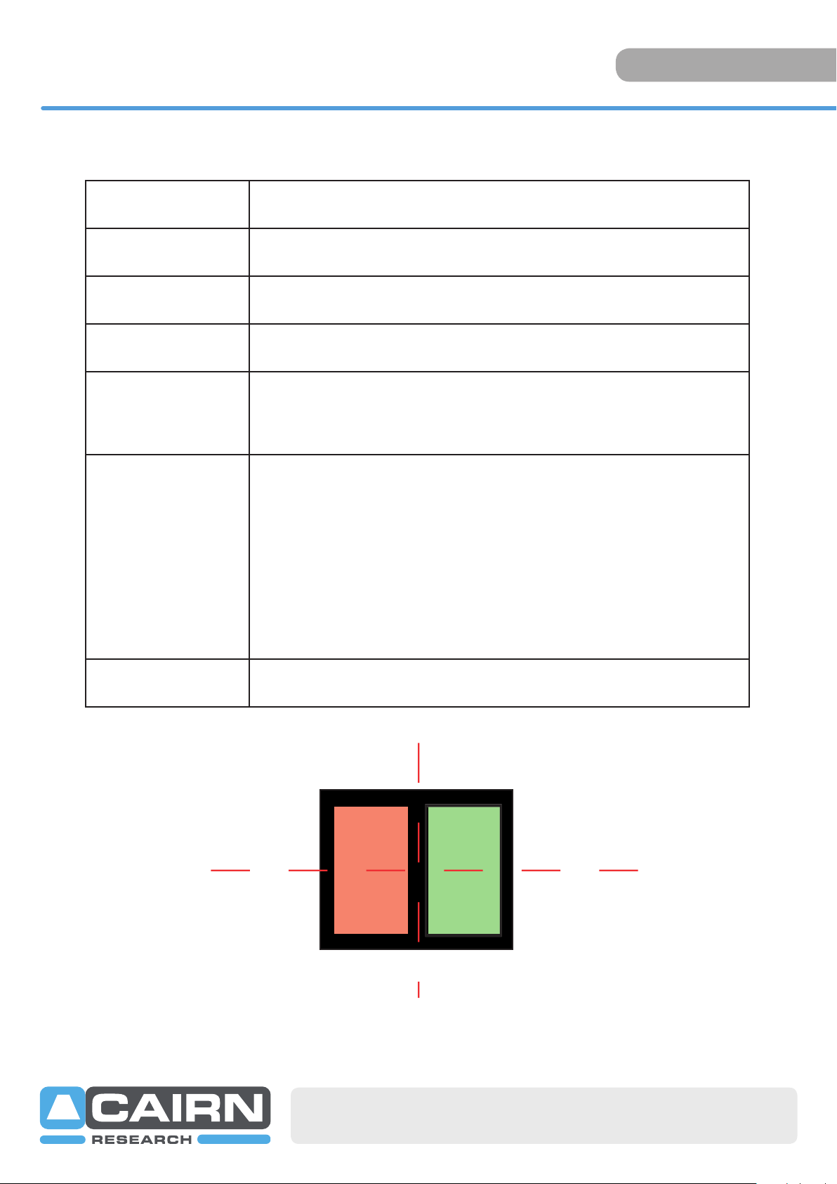
Here we see the two superimposed images. Although your image
may be monochromatic, colours have been used here to define the
two images.
Turning the Split control anti-clockwise will seperate the two images
along the horizontal axis. Only small adjustments will be required
when using the horizontal image seperation adjustment.
Should the left and right images be at different vertical heights then
adjust the images using the V1 and V2 adjuster. Turning V1 will alter
the position of the shorter wavelength image (right channel), and V2
will alter the position of the longer wavelength image (left channel).
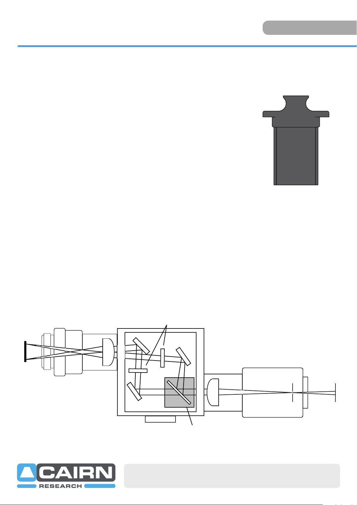
When the spectrally resolved images are side by side on the camera
chip you are ready to record. When carrying out experiments the ap-
erture should be set to mask the region of interest tightly so that the
two images are located as closely as possible on the camera chip.
Adjusting the Position of the Images
Although the camera can be sensibly orientated in any of four rotated planes at 90 degrees to the microscope,
we would recommend that it is set with a horizontal split and the V1 control adjusting the vertical height of the
right hand side channel. This is the convention used in this manual and will assist troubleshooting. When the cam-
era is mounted correctly, the split adjuster and the aperture control are the only controls that will be frequently
adjusted. The remaining adjusters on the body of the Optosplit II should remain untouched unless the filter set
has become misaligned. It may be easier to use the calibration cube for initial set up so that both channels display
the same information.
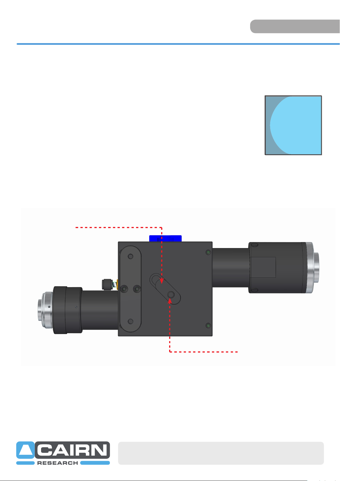
Adjusting and Locking the Aperture
The Optosplit II is supplied with an adjustable rectangular aperture that allows the user to determine the ROI both
vertically and horizontally.
Aperture adjusters
Aperture
mechanism
Turn aperture handles
to lock and unlock
the aperture adjusters

+44(0)1795 590140 www.cairn-research.co.uk
Set up guide
OPTOSPLIT II
Image Optimisation (Trim Adjustment)
Vignetting is when the image appears darker towards one edge. This
effect can be easily corrected by adjusting the trim control. To adjust the
trim control, loosen the clamp screw on the underside of the Optosplit II
by a quarter of a turn in order to free the slider which controls the trim
control. Gently move the slider until the vignetting is eliminated. If the slid-
er is moved too far then the vignetting will become apparent on the other
image and will need to be adjusted in the opposite direction until both
images are the same intensity. It is important to remember to re-tighten
the clamp screw once the adjustment is complete.
If the Optosplit II has been configured into single channel (non-split mode)
and Trim adjustment is required to compensate for vignetting being
observed, it is likely the slider will need to be at the extreme of its range of
movement to either end.
Vignetting is a darkening of the
image towards one edge.
Trim controller
Clamp screw

+44(0)1795 590140 www.cairn-research.co.uk
Set up guide
OPTOSPLIT II
Single channel (non-split) mode
When dual splitting is not required, the OptoSplit II unit can be used in bypass mode, allowing the unit to remain in
situ on the microscope whilst utilising the full camera chip to generate one image.
There are several ways this can be achieved:
A: Removing the Cairn filter cube
Suitable if no emission filters are required in the light path
• Remove the Cairn filter cube
• Centre the image using the Split control
• Open the aperture
• Adjust the Trim control to remove any vignetting
B: Blocking the longer wavelength path
Suitable if only the shortest wavelength channel is required
• Leave the Cairn filter cube in place and block the long wavelength path using the shutter plate provided in the
auxillary holder position. Most dichroic mirrors have long-pass characteristics, in which case the longest wave-
length will be the transmitted channel.
• Centre the image using the Split control
• Open the aperture
• Adjust the Trim control to remove any vignetting
C: Blocking the shorter wavelength path
Suitable if only the longest wavelength channel is required
• Follow the steps for option B, but block the short wavelength path (reflected channel) with the shutter plate
instead.
Cairn shutter plate
Cairn emission cube
Auxillary component holders
Other manuals for OptoSplit II
2
Table of contents
Other Cairn Cables And Connectors manuals
Popular Cables And Connectors manuals by other brands

Philips
Philips SWV3515S/10 user manual

PASCO
PASCO ME-1242 instruction manual

Rose electronics
Rose electronics UltraVista LC Installation and operation manual

Keithley
Keithley STA-3108A1 quick start guide

Hall Technologies
Hall Technologies ULTRA-V Series user manual

Weidmüller
Weidmüller BLF 7.62HP Series Assembly instructions