The TwinCam is a simple, yet powerful and stable device for pixel aligning images captured using different wavelengths,
polarization states, fields of view or other imaging modalities onto two camera sensors. It is designed to meet the most
demanding requirements for the sub-pixel mapping of Super Resolution imaging and is compatible with most scientific
C mount and F mount cameras.
Please contact us if you require any assistance during setup or use (Tech@cairn-research.co.uk).
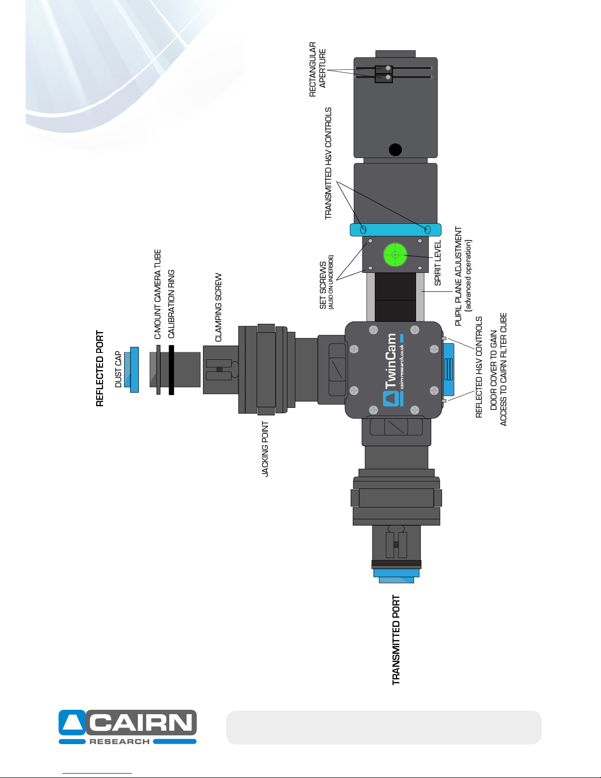
For the purpose of this Quick Start Guide, please refer to the TwinCam diagram on Page 3. All words in bold blue text are
labelled on this diagram.
1. Connect the TwinCam to your existing 1x camera c-mount (or confocal unit if appropriate).
2. If using an inverted microscope, two support jacks are normally supplied to support the weight of the unit. Position
the support jacks in the jacking point on each output. The height can be adjusted and locked in position with the blue
locking collar. A spirit level is also included in the input section to aid setup.
3. Remove the C-mount camera tube and protective dust cap. The clamping screw may need to be loosened (using the
2.5mm allen key provided).
4. Screw each camera onto the C-mount camera tube and replace on each arm of the TwinCam with the calibration ring
still in place.
A) Mounting to your microscope
+44(0)1795 590140 www.cairn-research.co.uk
B) Aligning two images
1. View a live image (ideally of a graticule using transmitted light) on the transmitted port. For initial setup, it is essential
to be able to view all four edges of the rectangular aperture, therefore it is not advisable to use a fluorescent sample at
this stage.
2. Close the rectangular aperture until in view on the image and rotate the camera until square.
3. Lock off the clamping screw.
4. Insert the calibration cube (containing a 50% mirror) into the unit by removing the magnetic door cover. Magnets will
ensure the cube locates correctly.
5. Repeat steps 1 to 3 on the reflected port.
6. If the sample focus of the reflected camera is not precisely matching the focus of the transmitted camera, an adjust-
ment is provided (to allow for any slight differences between positioning of the camera sensor). Remove the calibration
ring on the reflected port and move the camera in Z until focused. Lock off the clamping screw once again.
Each of the two images can now be overlaid in your imaging software and pixel aligned using two sets of XY controls:
7. With the rectangular aperture still in view, centre the transmitted port (using the 1.5mm allen key provided) by
adjusting the transmitted H&V controls. It’s useful to use a centred square or central crosshair as a reference point in
your imaging software (if available).
8. Centre the reflected port using the reflected H&V controls.
9. Note the reflected image will be mirrored horizontally, which will need to be flipped in your imaging software.
10. Replace the calibration cube with a filter cube for dual channel imaging (see section C).
11. Open the rectangular aperture to slightly larger than the camera field of view to minimize scattered light.