Cal Power IT-M3400 Series User manual

Bi-directional DC power
supply
IT-M3400 Series User Manual
Model: IT-M3400 Series
Version: V1.0/04,2020
Via Acquanera, 29 22100 Como
tel. 031.526.566 (r.a.) fax 031.507.984
info@calpower.it www.calpower.it

Notices
© Itech Electronic, Co.,
Ltd. 2020
No part of this manual
may be reproduced in any
form or by any means (in-
cluding electronic storage
and retrieval or translation
into a foreign language)
without prior permission
and written consent from
Itech Electronic, Co., Ltd.
as governed by interna-
tional copyright laws.
Manual Part Number
Trademarks
Pentium is U.S. registered
trademarks of Intel
Corporation.
Microsoft, Visual Studio,
Windows and MS Win-
dows are registered
trademarks of Microsoft
Corporation in the United
States and/or other coun-
tries and regions.
Warranty
The materials contained in this docu-
ment are provided “as is”, and is sub-
ject to change, without prior notice, in
future editions. Further, to the maxi-
mum extent permitted by applicable
laws, ITECH disclaims all warrants, ei-
ther express or implied, with regard to
this manual and any information con-
tained herein, including but not limited
to the implied warranties of merchant-
ability and fitness for a particular pur-
pose. ITECH shall not be held liable
for errors or for incidental or indirect
damages in connection with the fur-
nishing, use or application of this
document or of any information con-
tained herein. Should ITECH and the
user enter into a separate written
agreement with warranty terms cover-
ing the materials in this document that
conflict with these terms, the warranty
terms in the separate agreement shall
prevail.
Technology Licenses
The hardware and/or software de-
scribed herein are furnished under a li-
cense and may be used or copied only
in accordance with the terms of such
license.
Restricted Rights Legend
Restricted permissions of the U.S.
government. Permissions for software
and technical data which are author-
ized to the U.S. Government only in-
clude those for custom provision to
end users. ITECH follows FAR 12.211
(technical data), 12.212 (computer
software). DFARS 252.227-7015
(technical data–commercial products)
for national defense and DFARS
227.7202-3 (permissions for commer-
cial computer software or computer
software documents) while providing
the customized business licenses of
software and technical data.
Safety Notices
A CAUTION sign denotes
a hazard. It calls attention
to an operating procedure
or practice that, if not cor-
rectly performed or ad-
hered to, could result in
damage to the product or
loss of important data. Do
not proceed beyond a
CAUTION sign until the in-
dicated conditions are
fully understood and met.
A WARNING sign denotes
a hazard. It calls attention
to an operating procedure
or practice that, if not cor-
rectly performed or ad-
hered to, could result in
personal injury or death.
Do not proceed beyond a
WARNING sign until the
indicated conditions are
fully understood and met.
A NOTE sign denotes im-
portant hint. It calls atten-
tion to tips or
supplementary informa-
tion that is essential for
users to refer to.

Copyright © Itech Electronic Co., Ltd. I
IT-M3400 Series User Manual
Quality Certification and Assurance
We certify that series instrument meets all the published specifications at time
of shipment from the factory.
Warranty
ITECH warrants that the product will be free from defects in material and work-
manship under normal use for a period of one (1) year from the date of delivery
(except those described in the Limitation of Warranty below).
For warranty service or repair, the product must be returned to a service center
designated by ITECH.
•The product returned to ITECH for warranty service must be shipped PRE-
PAID. And ITECH will pay for return of the product to customer.
•If the product is returned to ITECH for warranty service from overseas, all
the freights, duties and other taxes shall be on the account of customer.
Limitation of Warranty
This Warranty will be rendered invalid in case of the following:
•Damage caused by circuit installed by customer or using customer own
products or accessories;
•Modified or repaired by customer without authorization;
•Damage caused by circuit installed by customer or not operating our prod-
ucts under designated environment;
•The product model or serial number is altered, deleted, removed or made il-
legible by customer;
•Damaged as a result of accidents, including but not limited to lightning, mois-
ture, fire, improper use or negligence.

Copyright © Itech Electronic Co., Ltd. II
IT-M3400 Series User Manual
Safety Symbols
Direct current ON ( power)
Alternating
current
OFF ( power)
Both direct and
alternating
current
Power-on state
Chassis (earth
ground) symbol.
Power-off state
Earth ( ground)
terminal
Reference
terminal
Caution Positive terminal
Warning ( refer to
this manual for
specific Warning
or Caution
information)
Negative terminal
A chassis
terminal
- -
Safety Precautions
The following safety precautions must be observed during all phases of opera-
tion of this instrument. Failure to comply with these precautions or specific warn-
ings elsewhere in this manual will constitute a default under safety standards of
design, manufacture and intended use of the instrument. ITECH assumes no li-
ability for the customer’s failure to comply with these precautions.

Copyright © Itech Electronic Co., Ltd. III
IT-M3400 Series User Manual
•Do not use the instrument if it is damaged. Before operation, check the
casing to see whether it cracks. Do not operate the instrument in the
presence of inflammable gasses, vapors or dusts.
•The instrument is provided with a power cord during delivery and should
be connected to a socket with a protective earth terminal, a junction box
or a three-phase distribution box. Before operation, be sure that the in-
strument is well grounded.
•Please always use the provided cable to connect the instrument.
•Check all marks on the instrument before connecting the instrument to
power supply.
•Ensure the voltage fluctuation of mains supply is less than 10% of the
working voltage range in order to reduce risks of fire and electric shock.
•Do not install alternative parts on the instrument or perform any unau-
thorized modification.
•Do not use the instrument if the detachable cover is removed or loosen.
•To prevent the possibility of accidental injuries, be sure to use the power
adapter supplied by the manufacturer only.
•We do not accept responsibility for any direct or indirect financial dam-
age or loss of profit that might occur when using the instrument.
•This instrument is used for industrial purposes, do not apply this product
to IT power supply system.
•Never use the instrument with a life-support system or any other equip-
ment subject to safety requirements.

Copyright © Itech Electronic Co., Ltd. IV
IT-M3400 Series User Manual
•SHOCK HAZARD Ground the Instrument. This product is provided with
a protective earth terminal. To minimize shock hazard, the instrument
must be connected to the AC mains through a grounded power cable,
with the ground wire firmly connected to an electrical ground (safety
ground) at the power outlet or distribution box. Any interruption of the
protective (grounding) conductor or disconnection of the protective earth
terminal will cause a potential shock hazard that could result in injury or
death.
•Before applying power, verify that all safety precautions are taken. All
connections must be made with the instrument turned off, and must be
performed by qualified personnel who are aware of the hazards involved.
Improper actions can cause fatal injury as well as equipment damage.
•SHOCK HAZARD, LETHAL VOLTAGES This product can outputinput
the dangerous voltage that can cause personal injury, and the operator
must always be protected from electric shock. Ensure that the outputin-
put electrodes are either insulated or covered using the safety covers
provided, so that no accidental contact with lethal voltages can occur.
•Never touch cables or connections immediately after turning off the in-
strument. Verify that there is no dangerous voltage on the electrodes or
sense terminals before touching them.
•After using the device, turn off the power switch of the device before un-
plugging the power cord or disassembling the terminals. Do not touch
the cable or the terminal immediately. Depending on the model, the dan-
gerous voltage at the plug or terminal is maintained for 10 seconds after
the device is switched off. Make sure that there is no dangerous voltage
before touching them.
•Failure to use the instrument as directed by the manufacturer may ren-
der its protective features void.
•Always clean the casing with a dry cloth. Do not clean the internals.
•Make sure the vent hole is always unblocked.
Environmental Conditions
The instrument is designed for indoor use and an area with low condensation.
The table below shows the general environmental requirements for the
instrument.

Copyright © Itech Electronic Co., Ltd. V
IT-M3400 Series User Manual
Environmental Conditions Requirements
Operating temperature 0℃~40℃
Operating humidity 20%~80%( non-condensation)
Storage temperature -20℃~70℃
Altitude Operating up to 2,000 meters
Installation category II
Pollution degree Pollution degree 2
In order to ensure the accuracy of measurement, it is recommended to
operate the instrument half an hour after start-up.
Regulation Tag
The CE tag shows that the product
complies with the provisions of all rel-
evant European laws (if the year is
shown, it indicates that the year when
the design is approved).
This instrument complies with the
WEEE directive (2002/96/EC) tag re-
quirements. This attached product
tag shows that the electrical/elec-
tronic product cannot be discarded in
household waste.
This symbol indicates that no danger
will happen or toxic substances will
not leak or cause damage in normal
use within the specified period. The
service life of the product is 10 years.
The product can be used safely within
the environmental protection period;
otherwise, the product should be put
into the recycling system.

Copyright © Itech Electronic Co., Ltd. VI
IT-M3400 Series User Manual
Waste Electrical and Electronic Equipment
(WEEE) Directive
Waste electrical and electronic equip-
ment (WEEE) directive, 2002/96/EC
The product complies with tag re-
quirements of the WEEE directive
(2002/96/EC). This tag indicates that
the electronic equipment cannot be
disposed of as ordinary household
waste. Product Category
According to the equipment classifi-
cation in Annex I of the WEEE direc-
tive, this instrument belongs to the
“Monitoring” product.
If you want to return the unnecessary
instrument, please contact the near-
est sales office of ITECH.

Copyright © Itech Electronic Co., Ltd. VII
IT-M3400 Series User Manual
Compliance Information
Complies with the essential requirements of the following applicable European
Directives, and carries the CE marking accordingly:
•Electromagnetic Compatibility (EMC) Directive 2014/30/EU
•Low-Voltage Directive (Safety) 2014/35/EU
Conforms with the following product standards:
EMC Standard
IEC 61326-1:2012/ EN 61326-1:2013 ¹²³
Reference Standards
CISPR 11:2015+A1:2016 Ed 6.1
IEC 61000-3-2: 2018 RLV
IEC 61000-3-3: 2013+A1:2017
IEC 61000-4-2:2008
IEC 61000-4-3 2006+A1:2007+A2:2010/ EN 61000-4-3 A1:2008+A2:2010
IEC 61000-4-4:2012
IEC 61000-4-5:2014+A1:2017
IEC 61000-4-6:2013+cor1:2015
IEC 61000-4-11:2004+A1:2017
1. The product is intended for use in non-residential/non-domestic environments. Use of the
product in residential/domestic environments may cause electromagnetic interference.
2. Connection of the instrument to a test object may produce radiations beyond the specified
limit.
3. Use high-performance shielded interface cable to ensure conformity with the EMC standards
listed above.
Safety Standard
IEC 61010-1:2010+A1:2016

Copyright © Itech Electronic Co., Ltd. VIII
IT-M3400 Series User Manual
Content
Quality Certification and Assurance .................................................................................. I
Warranty ............................................................................................................................ I
Limitation of Warranty........................................................................................................ I
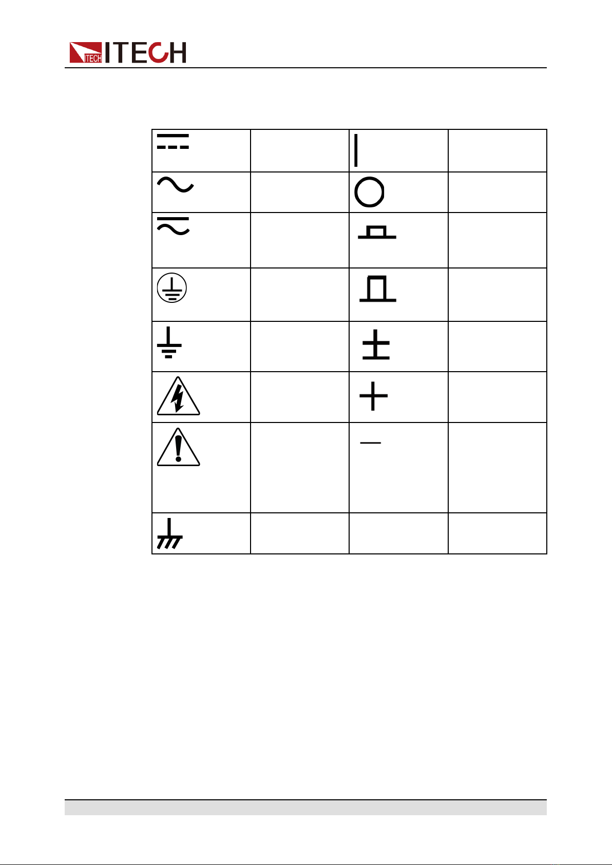
Safety Symbols................................................................................................................. II
Safety Precautions............................................................................................................ II
Environmental Conditions................................................................................................ IV
Regulation Tag ................................................................................................................. V
Waste Electrical and Electronic Equipment (WEEE) Directive ....................................... VI
Compliance Information.................................................................................................. VII
1 Quick Reference................................................................................................................. 1
1.1 Brief Introduction...................................................................................................... 1
1.2 Front-Panel Overview .............................................................................................. 2
1.3 Keyboard Introduction.............................................................................................. 3
1.4 Rear Panel Introduction ........................................................................................... 5
1.5 Home-Screen Overview........................................................................................... 6
1.6 Configuration Menu Reference................................................................................ 7
1.7 System Menu Reference ......................................................................................... 8
1.8 Models and Options ............................................................................................... 12
2 Inspection and Installation................................................................................................ 16
2.1 Verifying the Shipment........................................................................................... 16
2.2 Instrument Size Introduction .................................................................................. 17
2.3 Rack Mounting ....................................................................................................... 17
2.4 Connecting the Power Cord................................................................................... 18
2.5 Connecting the Device Under Test (DUT) ............................................................. 20
2.6 Connect the Communication Interface .................................................................. 23
2.6.1 USB Interface .............................................................................................. 24
2.6.2 GPIB Interface ............................................................................................. 25
2.6.3 LAN Interface............................................................................................... 26
2.6.4 RS-232 Interface ......................................................................................... 32
2.6.5 RS-485 Interface ......................................................................................... 34
2.6.6 CAN Interface .............................................................................................. 35
3 Getting Started ................................................................................................................. 38
3.1 Power-on the Instrument ....................................................................................... 38
3.2 Set output parameters ........................................................................................... 40
3.3 Use the Front Panel Menu ..................................................................................... 41
3.4 Output On/Off Control ............................................................................................ 42
4 Output Function................................................................................................................ 43
4.1 Set the Output Priority Mode.................................................................................. 43
4.2 Set the Output Voltage........................................................................................... 45
4.3 Set the Output Current........................................................................................... 46
4.4 Set the Output Power............................................................................................. 46
4.5 Set Output Slope.................................................................................................... 46
4.6 Enable the Output .................................................................................................. 47
4.7 Set the Internal Resistance.................................................................................... 47
4.8 Set the Output-On/Output-Off Delay ..................................................................... 47
5 Advanced Function........................................................................................................... 49
5.1 List function ............................................................................................................ 49
5.2 Battery Charging/Discharging Test Function......................................................... 54
5.3 Battery emulation function ..................................................................................... 57
6 Protect Function ............................................................................................................... 62
6.1 Set Over-Voltage Protection .................................................................................. 63
6.2 Set Over-Current Protection .................................................................................. 64
6.3 Set Over-Power Protection .................................................................................... 65
6.4 Set Under-Current Protection ................................................................................ 66
6.5 Set Under-Voltage Protection ................................................................................ 67

Copyright © Itech Electronic Co., Ltd. IX
IT-M3400 Series User Manual
6.6 UUT Over-Temperature Protection ...................................................................... 69
6.7 Sense abnormal protection function ...................................................................... 70
6.8 Over-Temperature Protection................................................................................ 70
6.9 Set foldback protection .......................................................................................... 71
7 System-Related Functions ............................................................................................... 73
7.1 Key Lock Function ................................................................................................. 73
7.2 Save and Recall Operations .................................................................................. 73
7.3 Local/Remote Mode Switch ................................................................................... 75
7.4 Basic Operation ..................................................................................................... 75
7.4.1 Set the Beeper Status ................................................................................. 75
7.4.2 Set the Power-on State ............................................................................... 76
7.4.3 Set the Sense Function State...................................................................... 76
7.4.4 Set the Communication Information............................................................ 76
7.4.5 Select Trigger Source.................................................................................. 77
7.4.6 Restore the Factory Default Settings .......................................................... 77
7.4.7 Observe the DUT Temperature and Total Historical Regenerative
Power........................................................................................................ 79
7.4.8 View the System Information....................................................................... 80
7.5 Measuring the DUT Temperature .......................................................................... 80
7.6 Observe the Regenerative power and Capaticy.................................................... 81
7.7 External analog function (optional) ........................................................................ 82
7.8 Anti-reverse connection module function (optional) .............................................. 89
8 Multi-Machine Operation .................................................................................................. 93
8.1 Multi-Channel Function.......................................................................................... 94
8.2 Synchronized Function (Link) ................................................................................ 96
9 Parallel Function (Parallel) ............................................................................................... 99
10 Routine Maintenance ................................................................................................... 103
10.1 Instrument Self-Test .......................................................................................... 103
10.2 Cleaning and Maintenance ................................................................................ 103
10.3 Information Reference ....................................................................................... 104
10.4 Contact of ITECH Engineers ............................................................................. 105
10.5 Return for Repair ............................................................................................... 106
11 Technical Specification ................................................................................................ 108
11.1 IT-M3412............................................................................................................ 108
11.2 IT-M3422............................................................................................................ 111
11.3 IT-M3432............................................................................................................ 113
11.4 IT-M3413............................................................................................................ 116
11.5 IT-M3423............................................................................................................ 118
11.6 IT-M3433............................................................................................................ 121
11.7 IT-M3414............................................................................................................ 123
11.8 IT-M3424............................................................................................................ 125
11.9 IT-M3434............................................................................................................ 128
11.10 IT-M3415.......................................................................................................... 130
11.11 IT-M3425.......................................................................................................... 133
11.12 IT-M3435.......................................................................................................... 135
A Appendix ........................................................................................................................ 138
A.1 Specifications of Red and Black Test Cables ..................................................... 138

Quick Reference
1Quick Reference
This Chapter will introduce power-on check steps of this series to ensure normal
start-up and usage under initialization status of the powerload. Besides, to facili-
tate usage, this part also displays the functions of front board, rear board and
keyboard keys as well as display functions to a quick view of powerload appear-
ance, structure and key usage functions before operation.
♦Brief Introduction
♦Front-Panel Overview
♦Keyboard Introduction
♦Rear Panel Introduction
♦Home-Screen Overview
♦Configuration Menu Reference
♦System Menu Reference
♦Models and Options
1.1 Brief Introduction
IT-M3400 bidirectional DC power supply integrates the features of a
bidirectional power supply and a regenerative load. It keeps the advantages of
high power density and modular architecture design of M series.
It can meet the customer's test requirement of different current and power level.
Thanks to the independent multi-channel design, users can configure each
channel according to the quantity and specifications of the DUT. At the same
time, it has high-precision output and measurement, and has made a number of
safety designs for testing, suitable for multiple test fields, such as power
modules, intelligent industrial equipment, automotive electronics, charging and
discharging tests of various small-capacity batteries.
Source features:
•Programmable voltage and current
•CC/CV priority
•Programmable rise/fall time for voltage and current
•Adjustable output impedance
•Battery charge test
•Various protection such as OCP,OVP,OPP,UVP,UCP
System features:
•Bidirectional energy flow and support battery simulation
Copyright © Itech Electronic Co., Ltd. 1

Quick Reference
•Support On/Off delay
•Automatic detection of power grid state to realize reliable grid connection
•Parallel up to 16 units
•Independent control of multi-channels,implement synchronization or
proportional tracking
•sense abnormal protection
•Temperature measurement function,over temperature protection
•Anti-reverse protection function through optional accessories
•Power-off protection
•Five optional cards, supporting RS232, CAN, LAN, GPIB, USB_TMC, USB_
VCP, RS485, analog and IO communication
•High-speed measurement, keep 10 times / s update rate even connecting
16 stand-alone units
1.2 Front-Panel Overview
The detailed descriptions of IT-M series front panel are shown as below.
No. Name Description
1[Shift] key Composite key, combined with other keys to realize
functions as marked above keys.
2[Link](Local)
Key
•Turn the synchronized operation feature on or
off. When lit, indicates that the instrument is in
synchronous.
•In remote control, press [Shift]+[Link] keys to
switch the instrument to local control mode.
3 Power On/Off
switch
Turns instrument on or off.
Copyright © Itech Electronic Co., Ltd. 2

Quick Reference
No. Name Description
4 Vacuum
fluorescent
display (VFD)
Displays all instrument functions. The information
changes based on selected function.
5 Function keys
group
Refer to 1.3 Keyboard Introduction for the detailed
description about the function keys.
6 Push-on knob •Rotate the knob to adjust the setting values or
scroll pages to view menu items. Rotate the
knob clockwise to increase the set value and
anticlockwise to decrease the set value.
•Pushing the knob acts like pressing [Enter] key
to confirm an operation.
7 Left, and right
arrow keys
•Moves the cursor below the setting value or
scrolls pages to view menu items.
•Save/Recall the present settings.
1.3 Keyboard Introduction
The keyboard introduction of IT-M3600 series power supplies is shown as
follows.
Copyright © Itech Electronic Co., Ltd. 3

Quick Reference
Keys Description
[V-set] Set the voltage value
In CV priority (default) mode, press [V-set] and set the
output voltage value. In CC priority mode, press[V-set]
and set the upper limit of voltage.
[I-set] Set the current value
In CV priority, press [I-set] and enter the current value
setting state. Repress [I-set] and setting the I+ limit and I-
limit. In CC priority, press [I-set] to setting the output
current.
[P-set] Set the power value
[R-set] Set the resistance value.
[On/Off] Power supply output on/off key
[Enter] Operation confirmation key.
[Esc] Press this key to cancel the present input or exit the
present operation interface.
The left navigation keys is used to adjust the cursor to the
specified position or scrolls pages to view menu items.
Long pressing this key and enter to save function, and
key is light.
The right navigation keys is used to adjust the cursor to
the specified position or scrolls pages to view menu items.
Long pressing this key and enter to recall function, and
key is light.
Composite key [Shift], combined with other keys to realize functions marked
above keys. The detailed functions are listed as follows.
Keys Description
[Shift]+[V-set](Config) Enter the Config menu. Used to set the
configuration parameters.
[Shift]+[I-set](Function) Enter the Function menu. Used to set the list
function, Battery test function.and battery
simulation..
[Shift]+[P-set](System) Enter the system menu. Used to set the system
parameters.
Copyright © Itech Electronic Co., Ltd. 4

Quick Reference
Keys Description
[Shift]+[R-set](Protect) Enter the protection menu. Used to set the
protection parameters.
[Shift]+[On/Off]
(Trigger)
Generate a local trigger signal.
[Shift]+[Enter](lock) Turn the keyboard lock on or off.
[Shift]+ (Save) Save the common parameter settings.
[Shift]+ (Recall) Returns the instrument to the specified setup.
1.4 Rear Panel Introduction
The detailed descriptions of the rear panel are shown as below.
No. Name Description
1 DC terminals DC+, DC- output terminals and ground terminals,
used to connect DUT.
2 Protective cover Protective cover for DC terminals and remote
sense terminals. prevent user touching.
3 Remote sense
terminals
used for maximizing measurement accuracy.
4 Optional
expansion slot
Optional interfaces: (Plastic plugs are inserted by
default when the user does not purchase the
interface.)
The optional interface as follows:
•USB/LAN
•GPIB
Copyright © Itech Electronic Co., Ltd. 5

Quick Reference
No. Name Description
•RS-232/CAN
•Analog interface/RS-485
5 Temperature
measure
terminals
Used to measure the temperature of DUT.
6 System Bus Used for communication between instruments in
parallel operation, multichannel operation and
synchronized operation features.
7 AC power input
terminals
Used to connect AC power to start instrument,
supports 110 V or 220 V.
1.5 Home-Screen Overview
The screen information displayed as below.
No. Name Description
1 Output Voltage Displays the present output voltage value.
2 Output Current Displays the present output current value.
3 Voltage Setting
value
Displays the present voltage setting value.You can
change these value by pressing the [V-set] key on
the front panel.
4 Current Setting
value
Displays the present current setting value, you can
change these value by pressing the [I-set] key on
the front panel.
Copyright © Itech Electronic Co., Ltd. 6

Quick Reference
No. Name Description
5 Output status •OFF: Output is disabled.
•Displays the present output status when the
output is enabled.
6 The indication for
current direction
Indicates present current setting value is positive
current limit.
The indication displays only in CV priority
mode.
1.6 Configuration Menu Reference
Press [Shift]+[V-Set](Config)to enter into the configuration menu interface. The
instrument return to home-screen automaticly when no action in a long time.
Config configuration of source
Mode Set the output priority mode
CV Priority Voltage priority mode
CC Priority Current priority mode
V-Rise Time Voltage rising time When select CV priority, the menu
shows the two items
V-Fall Time Voltage falling time
I-Rise Time Current rising time When select CC priority, the menu
shows the two items
I-Fall Time Current falling time
Output R Set the internal resistance.
On Delay Set the output-on delay time.
Off Delay Set the output-off delay time.
Off Voltage
Displays when select CC priority, set to zero, instrument
voltage falls to 0 quicklly, set to const, instrument voltage
falls to 0 as usual.
Copyright © Itech Electronic Co., Ltd. 7

Quick Reference
1.7 System Menu Reference
Press [Shift]+[P-Set](System) to enter into the system menu interface. At this
point, the VFD screen displays the system menu items. Each menu item has a
numbering identifier. The user can press Up and Down buttons or use the knob
for scrolling display of other menu items. Press [Enter]on a menu interface to
enter the setting interface. Press [Esc]to return to the previous menu. The
instrument return to home-screen automaticly when no action in a long time.
The description of the menu items is shown in the table below.
System System menu
Beep Set the beeper state.
Off Turn the beeper off.
On Turn the beeper on.
PowerOn Set the power-on state.
Reset When the instrument is powered on, the instrument
will initialize some settings and [On/Off] state.
Last
When the instrument is powered on, the instrument
will remain the same settings and [On/Off] state as
last time you turned off the instrument.
Last+Off
When the instrument is powered on, the instrument
will remain the same settings as last time you turned
off the instrument, but the [On/Off] is OFF state.
Sense Set the sense measurement function
Off Turn the sense function off.
On Turn the sense function on.
I/O Config Select the interfaces communicating with PC and display dynamic
information of different interface card.
None No optional communication interfaces.
USB+LAN When insert IT-E1206 communication board into
expansion slot, the menu displays this information.
USB USB communication interface.
TMC USB-TMC protocol
VCP Virtual serial port
LAN LAN communication interface.
Lan Info View the LAN information.
Status
IP Mode Status
IP Addr
Sub Net
Copyright © Itech Electronic Co., Ltd. 8

Quick Reference
Gateway
DNS1
DNS2
MAC Addr
MDNS Status
Host Name
Host Desc
Domain
TCPIP INSTR
Socket Port
Lan
Config Configure LAN information.
IP Mode Set IP mode.
Auto: automatically configure
the address of the instrument.
Manual: manually configure
the address of the instrument
by entering values in the
following five fields.
The following information only
appear when Manual is
selected.
IP Addr
Sub Net
Gateway
DNS1
DNS2
Server
Config Configure the LAN services.
mDNS: mDNS service state.
Off
On
Ping: Ping service state
Off
On
Telnet: telnet service state.
Off
On
Web: web service state.
Off
On
VXI-11: VXI-11 service state.
Off
On
Raw Socket: RAWSocket
service state.
Off
On
Lan
Restore
Select whether to reset the LAN to the
default settings or not.
Copyright © Itech Electronic Co., Ltd. 9
Table of contents
Other Cal Power Power Supply manuals
Popular Power Supply manuals by other brands

GTV
GTV SLIM HQ LD-SZAHQ06W-MA manual

CIOKS
CIOKS DC10 user manual

Pico Macom
Pico Macom MPC12R Specifications

Manson Engineering Industrial
Manson Engineering Industrial ZPS-9160 Operation manual

Solar Stik
Solar Stik PRO-VERTER 5000-220 AFF1 troubleshooting guide

EA-ELEKTRO-AUTOMATIK
EA-ELEKTRO-AUTOMATIK EA-PS 500 Series User instruction guide