Cal Power ITech IT6860B Series User manual

IT6860B User manual
用户使用手册
1
User Manual
Programmable DC power supply
IT6860B series
Model IT6861B/IT6862B/IT6863B
© Copyright 2011 All Rights Reserved
Ver1.1/JUN, 2011/ IT6800A-603
Via Acquanera, 29 22100 Como
tel. 031.526.566 (r.a.) fax 031.507.984
info@calpower.it www.calpower.it

IT6860B User manual
用户使用手册 2
Security................................................................................................................................3
Security regulation .............................................................................................................3
Safety symbols....................................................................................................................3
Certification and Quality Assurance .................................................................................3
Chapter1 Inspection and Installation................................................................................................5
1.1 Inspection.................................................................................................................................................... 5
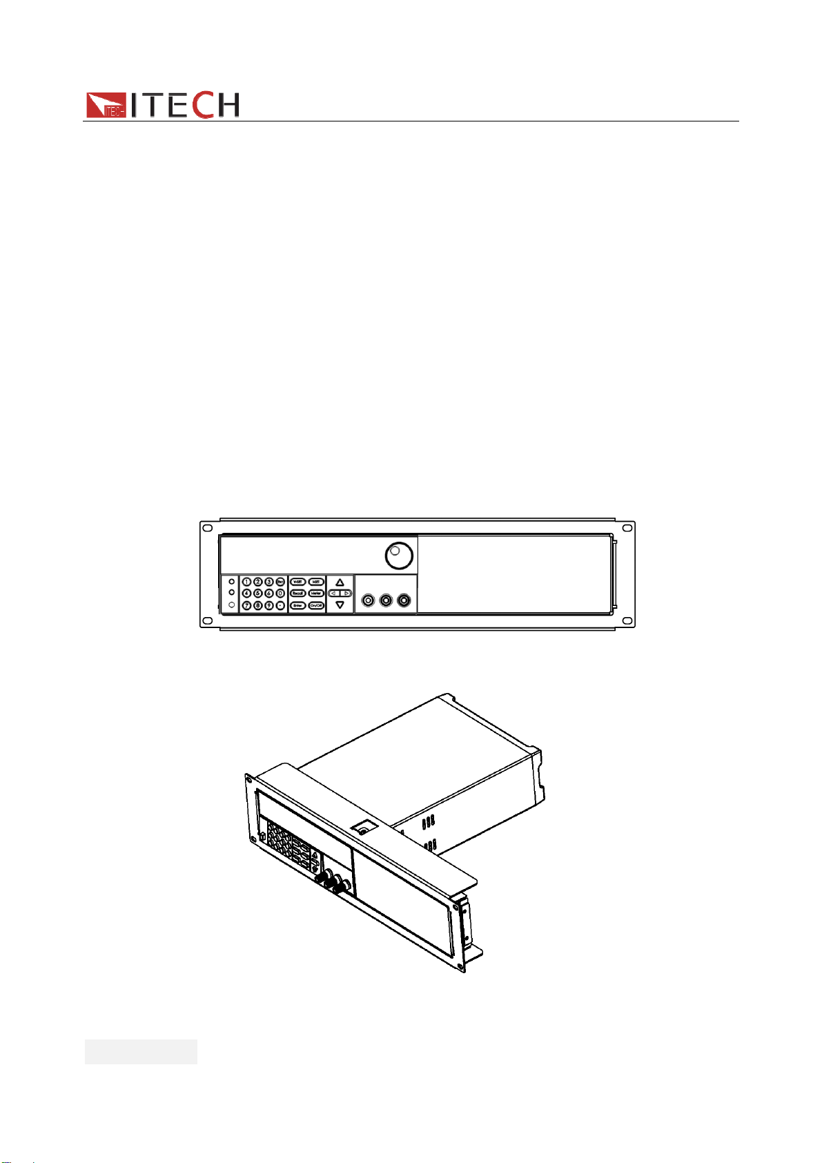
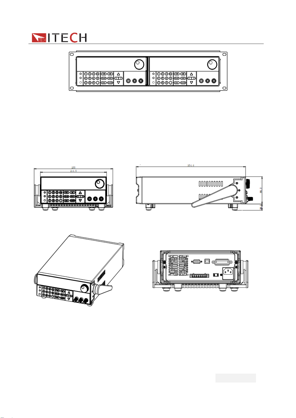
1.2 To Rack Mount the Instrument................................................................................................................. 6
1.3 The size of the power supply ................................................................................................................... 7
Chapter 2 Quick Start............................................................................................................8
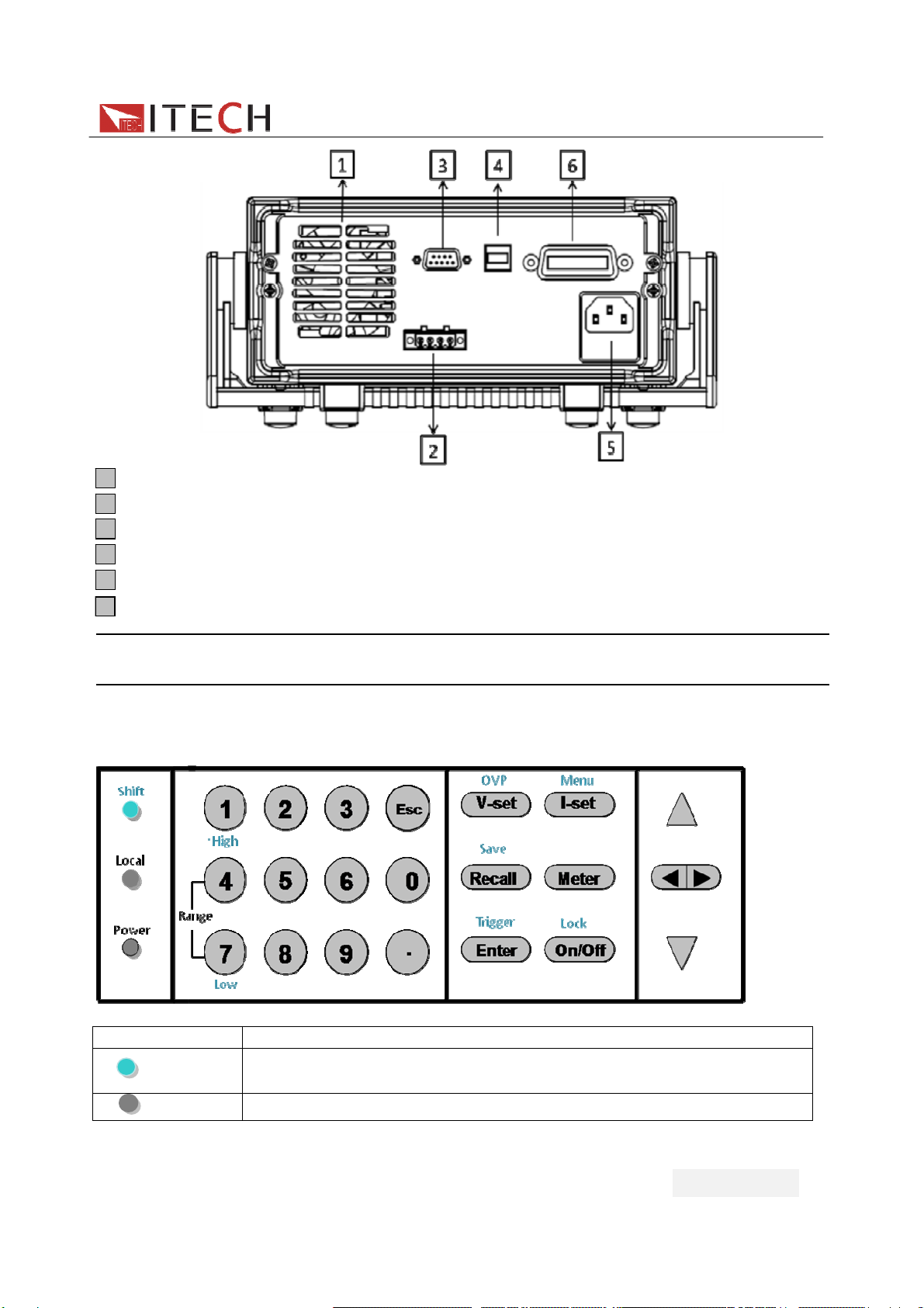
2.1 The front and rear panel description ....................................................................................................... 8
2.2 Keypad introduction................................................................................................................................... 9
2.3 VFD Description ....................................................................................................................................... 10
Chapter 3 power on check .................................................................................................. 11
3.1 power on Pre-check................................................................................................................................. 11
1.Power on the power supply............................................................................................................. 12
2.System self-test ................................................................................................................................ 13
3.2 Output Verification ................................................................................................................................... 14
2.Current Output check....................................................................................................................... 14
Chapter 4 specification .......................................................................................................15
4.1 main technical parameters ..................................................................................................................... 15
4.2 supplementary characteristic ................................................................................................................. 16
Chapter5 Front-panel Operations .......................................................................................17
5.1 Local/remote ............................................................................................................................................. 17
5.2 Dual-range switch .................................................................................................................................... 17
5.3 Voltage setting.......................................................................................................................................... 17
5.4 Current setting.......................................................................................................................................... 18
5.5 Output on/off ............................................................................................................................................. 18
5.6 switch the actual/setting value display.................................................................................................. 18
5.7 CC/CV mode............................................................................................................................................. 18
5.8 Save/Recall............................................................................................................................................... 18
5.9 Trigger operation ...................................................................................................................................... 19
5.10 Menu Operation ..................................................................................................................................... 19
1. Menu structure ................................................................................................................................. 19
2. Menu Function .................................................................................................................................... 21
5.11 OVP Function ......................................................................................................................................... 25
5.12 KEY LOCK .............................................................................................................................................. 26
5.13 Remote Sense Function ....................................................................................................................... 26
Chapter6 RemoteOperation ......................................................................................................27
6.1 RS232 interface........................................................................................................................................ 27
6.2 USB interface............................................................................................................................................ 29

IT6860B User manual
用户使用手册
3
IT6860B Series Programmable DC Power Supplies
Security
Please do not install replacement parts in the instrument, or perform any unauthorized
modification. Please send the instrument to our company's maintenance department for
maintenance, to ensure its security features.
Please refer to the manual for specific information warning or precautions to avoid personal
injury or equipment damage.
There is no part that the operators can maintenance. If maintenance service is required,
please contact trained service personnel.
Security regulation
To prevent electric shock, a non-authorized personnel is strictly not allowed to open the
machine.
This equipment is strictly prohibited for use in life support systems or any other device with
security requirements.
We cannot accept responsibility for any direct or indirect financial damage or loss of profit
that might occur when using the electronic load.
Safety symbols
Warning
It reminds the user, note some operating procedures, practices, conditions and other
matters, that may lead to human casualties.
Notes:
It reminds the user of some operating procedures, practices, conditions and other matters
that may result in instrument damage or data lose forever.
Connect it to safety earth ground using the wire recommended in the user
manual.
The symbol on an instrument indicates that the user should refer to the operating
instructions located in the manual.
High voltage danger
Certification and Quality Assurance
IT6900A series programmable DC power supply fully meet all of the technical specification
in the manual.
Warranty
Our Company gives one year warranty for the materials and manufacturing of the product
since the date of shipment.

IT6860B User manual
用户使用手册 4
Warranty Service
For the warranty service or repair the product, the product must be returned to the
designated maintenance units. Return the product to us for warranty service, the customer
should pre-pay the one-way Freight to the maintenance department. And our company is
responsible for the return shipping cost.
If products are returned from other countries for maintenance service, then the customer
should pay all freight, duties and other taxes.
Guarantee limit
The guarantee does not apply to the damage caused by the following conditions:
Improper or inadequate maintenance to the products by customer;
Customers use their own software or interface;
Unauthorized modification or misuse;
Operate this product not in the specified environment, or at the wrong place configuration
and maintenance.
Damage from Customer self-installation of circuit, or defects due to customers use their
products.
Product model or serial number of the fuselage has been altered, deleted, removed or made
illegible;
Damage caused by accidents including but not limited to lightning, water, fire, abuse or
neglect.
Notice
If the content of this manual is subject to change, we will not notice additionally.
Introduction
IT6860B series power supply is single output dual range DC programmable power supply,
which can replace two ordinary ones. The front panel keys and the control knob provide a
convenient interface for adjusting voltage and current, storing and recalling operation.
Built-in RS232/USB/GPIB communication interface is suitable for either bench or rack
mounted operation. Can be designed and tested according to your needs and provide
multi-purpose solutions.
Dual range ouput
VFD display
Digital keypad operation
High accuracy and high resolution
Low ripple and low noise
Intelligent fan control, energy conservation, noise reduction
Can be monitored by computer software
Output voltage and current values accordance with procedure
Can use the knob to adjust the voltage and current
Can adjust the numbers steps using the cursor
Can set the output timer(0.1~9999.9S)
Standard RS232/USB/GPIB communication interface
Rich SCPI orders and IT6820 compatiable frame protocol to facilitate the formation of

IT6860B User manual
用户使用手册
5
intelligent test platform
Model Voltage Current Power
IT6861B 0~20V/ 0~8V 0~5A/ 0~9A 0~100W/ 0~72W
IT6862B 0~32V/ 0~12V 0~3A/ 0~6A 0~96W/ 0~72W
IT6863B 0~72V/ 0~32V 0~1.5A/ 0~3A 0~108W/ 0~96W
Chapter1 Inspection and Installation
Power supply is high level safety equipment; there is a protected ground terminal.
Before Installation or operation, please read the safety signs and instructions in this manual
1.1 Inspection
After received the power supply, follow these steps to check it:
1. Check for damage in the equipment during transport
If the frame, panel is damaged, or abnormal working, ext. Please contact immediately with
our authorized dealer or service department. Do not return the instrument before positive
response has not been got.
2. Check the attachment
Make sure you receive the power and the following components at the same time, if any
missing, please contact your nearest dealer.
□a power cord (in accordance with the standard voltage used in the region,see the below
picture)
□an operating manual.
□a factory calibration report
□a certificate
□USB cable
Power cord type
E
NL
E
LN
E
NL
E
LN
China USA,Canada Uurope England
IT-E171 IT-E172 IT-E173 IT-E174

IT6860B User manual
用户使用手册 6
3. The power input requirements
There are two kinds of working voltage for the power supply: 110V and 220V, so please pay
attention to the working input voltage. There is a power cord which matches with your local
power in the attachment. If that does not match, please do not hesitate to contact with our
authorized dealer or service department.
AC input levels (select by change the AC power switch on the bottom of the power supply)
Option Opt.01: 220VAC ± 10%, 47 to 63 Hz
Option Opt.02: 110 VAC ± 10%, 47 to 63 Hz
1.2 To Rack Mount the Instrument
You can mount IT6860B series power supply in a standard 19-inch rack cabinet using the
IT-E151 rack mount kit.
The procedure:
Remove the carrying handle before rack-mounting the instrument. To remove the handle,
grasp the handle by sides and pull outwards and rotate it to a special position (vertical to the
Power supply), then pull the handle outward. After removing the handle, you can tear the
lables on both side, and then you can see the screw holes.
PIC 1.1 Rack mount a single instrument with rack mount kit IT-E151
PIC1.2 Side view of rack mounting a single instrument

IT6860B User manual
用户使用手册
7
PIC 1.3 To rack mount two instruments side-by-side, order rack mount kit IT-E151, you
needn’t to use the front cover panel.
1.3 The size of the power supply
1. The size of IT6860B series power supply
214.5mmW×88.2mmH×354.6mmD
* refer to the Dimensions below:
Unit: MiliMeter(mm)
PIC 1.4 The dimension of IT6860B power supply

IT6860B User manual
用户使用手册 8
Chapter 2 Quick Start
This chapter introduces the front panel, the rear panel, key functions and VFD display
function of the IT6860B power supply, make sure that you can quickly know the appearance,
instruction and the key function before you operate the power supply, Help you make better
use of this series of power supply.
2.1 The front and rear panel description
1
VFDdisplay
2
Rotary knob
3
Compound key, the local switch key and power switch
4
Number keys and ESC escape key
5
Function keys
6
UP、DOWN, LEFT and RIGHT key, to move cursor
7
Output terminals

IT6860B User manual
用户使用手册
9
1
Cooling window
2
Remote sense terminal
3
RS232 communication interface
4
USB communication interface
5
AC power socket(fuse contained)
6
GPIB communication interface
Note: the AC power switch is at the bottom of the power supply. To avoid any damage,
please make sure it is in the right position before you power on the supply.
2.2 Keypad introduction
Keypad description, see the table below:
Keys Name and the function
Shift Compound key,co-work with OVP、Menu、Save、Trigger、Lock、
and numeric key 4 and 7
Local Local switch key, switch from remote mode to local operation mode

IT6860B User manual
用户使用手册 10
Power Power on key
0-9 Numeric keys
V-setV-set
OVP Voltage set key, set the output voltage/over voltage protection point
for the power supply
I-setI-set
Menu Current set key, set the output current/menu function key, to set the
relevant Parameters for the power supply
Recall
Save Callback key to call up a set value of system parameters already
stored / storage key, to save system parameter settings
MeterMeter
Meter key, to switch from value set panel and the actual output value
display
EnterEnter
Trigger Enter key, to confirm the number entered and operation / trigger
button, which is used to trigger the List test.
On/Off
Lock Output on (off) keys, control power output state / keypad lock function
keys, used to lock the panel buttons
Left and right movement keys, used to set the value, to adjust the
cursor to the specified location
Up and down keys, used to select a item in the menu or increase
(decrease) the output voltage or current values
Escape key
2.3 VFD Description
char Function char Function
OFF Output is off Timer Output on timer function is
enabled
CV The power supply is in constant
voltage mode Sense Not in use
CC The power supply is in constant
current mode Ext Not in use
* The power supply is in high
voltage range Adrs (USB)light when the address
match or (RS232) received
order
Meter “Meter” key is pressed Rmt The power supply is in remote
mode

IT6860B User manual
用户使用手册
11
Shift Shift key is pressed,Use
compound keys Error The power supply has error or
fault
OVP OVP function is enabled Prot The power supply is in OVP
/OTP protection
OCP Not in use Lock Keypad is locked
Chapter 3 power on check
This chapter will introduce the procedure of power on check for IT6860B, including
pre-check and output check, to make sure the power supply can power on and work
normally on the original state.
3.1 power on Pre-check
Before operation the power supply, please read the following safty guide:
Warning:The AC input voltage is 110V or 220V, please check the switching at the
bottom of the power supply, to make sure it matches the voltage in your
city. Otherwise, the power supply may be damaged.
Warning:The power supply provides a three-wire power cord, you should plug it
to a three cord junction box. You should also make sure the power supply is
well grouded.
Warning:The connection wire should have enough current capacity that it can
bear the max rated current/short current of the power supply and not get
too hot.
Warning:To avoid any fire or electric shock, please ensure the AC input voltage
fluctuation not exceed 10% of the working voltage range.
Note:In some situation, use the miscongfiged main voltage for the instrument may
cause the main fuse blew.

IT6860B User manual
用户使用手册 12
Note:If the power supply is used to charge a battery, please pay attention to the
positive and negative polarity to avoid any damage.
Power on pre-check includes two parts: power on the supply and system self check.
1.Power on the power supply
If Power Supply Does Not Turn On
Use the following steps to help solve problems you might encounter when turning on the
instrument.
(1)Verify that there is AC power to the power supply.
First, verify that the power cord is firmly plugged into the power receptacle on the rear panel
of the power supply. You should also make sure that the power source you plugged the
power supply into is energized. Then, verify that the power supply is turned on.
(2) Verify the power-line voltage setting.
Make sure the voltage selector switch is set according to the present line voltage
(110VAC or 220VAC) when the power supply is shipped from the factory. Change the
voltage setting if it’s not correct.
(3)Verify that the correct power-line fuse is installed.
If the fuse was damaged, please see the table below to replace the fuse for your power
supply.
Model Fuse
Specifications
(110VAC)
Fuse
Specifications
(220VAC)
IT6860B
T5A 250V
T2.5A 250V
IT6862B
IT6863B
(4)How to exchange the fuse
Open the small plastic cover below the power supply input socket on the back panel with a
screwdriver, and you can see the fuse in it, please use the specifications in line fuse.
Remove the power cord and then use a screwdriver to remove the fuse box.

IT6860B User manual
用户使用手册
13
Use the same specification of fuse to replace the old one,install it to the fuse box and then
insert .
2.System self-test
After power on normally, the supply will enter self -test first.
During this time, the following should be displayed:
If the self-test is pass, then the VFD will display:
In case the self-test is not successful, you may see one of the followings:
About 1second after power on, if the EEPROM was damaged, the VFD will display
(about 1 S):
If the last power status in EEPROM is lost, then VFD will display information (about 1 S)
as below:
If the calibration data in EEPROM is lost, then VFD will display (about 1S) as below:
If the factory calibration data in EEPROM is lost, and then the VFD will display(about 1
S) as below:
EEPROM FAIL
SYST LOST
CAL LOST
FACT LOST
INIT….
SCAN SYSTEM
OFF
0.000V 0.0000A

IT6860B User manual
用户使用手册 14
3.2 Output Verification
IT6860B is dual range output, the following procedures verify that the power supply outputs
the correct voltage and current levels and properly responds to entries from the front panel.
1.Voltage Output Check
The following steps verify basic voltage functions without load.
High voltage range voltage check:
1) Turn on the power supply
2) Press
I-setI-set
to set the current value (≥0.0001A).
3) Enable the outputs
Press
On/Off
to let the ON annunciator and the CV annunciator turn on to light.
4) Turn on Meter mode
Press
MeterMeter
to light the button, the Meter status Mark light on the display is turned
on.
Notice:if the voltage value flash, then the power supply is in Set mode, ‘‘Set mode’’
means that the VFD display shows the setting output voltage and current. Or the
power supply is in Meter mode, ‘Meter mode” means that the VFD display shows the
actual output voltage and current.
5) Press (Shift) +4 to switch to high voltage range, and then set the voltage level.
Set different voltage values, check the voltage value displayed on the VFD is close to
the voltage value you set, and to check if the VFD displayed current value is nearly
zero.
6) Ensure that the voltage can be adjusted from zero to the full rated value
Low voltage range voltage check:
7) Press (Shift) +7 in the above step 5 instead to switch to low voltage range, and
then repeat step 5~6
2.Current Output check
The following steps check basic current functions with a short across the power supply’s
output.
High voltage range current check:
1) Turn on the power supply
2) Enable the output
Press
On/Off
key to ensure that the output is disabled. At the same time, the OFF status
mark is on the VFD.
3) Connect a short across (+) and (-) output terminals with an insulated test lead, use a wire
sufficient to handle the maximum current.
4) Adjust the voltage value to 1V.
5) Turn on the power output.
Press
On/Off
key to ensure the output is enabled, at the same time there is CC status
sign on the VFD.
6) Turn on Meter mode
Press
MeterMeter
to light the button, the Meter status Mark light on the display is turned on.

IT6860B User manual
用户使用手册
15
7 ) Adjust the current value
Set some different current values, check whether the voltage value on VFD is near 0v, and
the current on it is close to the value you set.
8) Make sure that the current can be adjusted from 0 to full rated value.
Low voltage range current check:
9)Press (Shift)+4 to switch to high voltage range, repeat step 7~8 above,verify if the
current can adjust from 0 to full rated value
10)Turn off the output of the power supply, and remove the short wire.
Chapter 4 specification
This chapter will introduce the main technical parameters of IT6860B, such as rated
voltage/current/power and so on. Besides, we will introduce the working environment and
storage temperature.
4.1 main technical parameters
Model IT6861B IT6862B IT6863B
Output
Ratings Dual range output 0-20V,5A/0-8V,9A 0-32V,3A/0-12V,6A 0-72V,1.5A/0-32V,3A
Load
regulation Voltage ≤0.01%+4mV ≤0.01%+3mV ≤0.01%+3mV
Current ≤0.01%+2mA ≤0.01%+2mA ≤0.01%+2mA
Line
regulation Voltage ≤0.01%+4mV ≤0.01%+3mV ≤0.01%+3mV
Current ≤0.01%+2mA ≤0.01%+2mA ≤0.01%+2mA
Programming
Resolution Voltage 1mV 1mV 1mV
Current 0.1mA 0.1mA 0.1mA
Readback
resolution Voltage 1mV 1mV 1mV
Current 0.1mA 0.1mA 0.1mA
Programming
accuracy
12 month
(25℃±5℃)
Voltage ≤0.04%+8mV ≤0.04%+8mV ≤0.04%+8mV
Current ≤0.1%+5mA ≤0.1%+5mA ≤0.1%+5mA
Readback
accuracy
12 month
(25℃±5℃)
Voltage ≤0.04%+8mV ≤0.04%+8mV ≤0.04%+8mV
Current ≤0.1%+5mA ≤0.1%+5mA ≤0.1%+5mA
Ropple&Noise Normal mode
Voltage ≤2mVp-p and
0.5mVrms
≤3mVp-p and
0.5mVrms
≤3mVp-p and
1mVrms

IT6860B User manual
用户使用手册 16
(20HZ-20M) (20V/5A) (32V/3A)
Normal mode
Voltage
≤3mVp-p and
1mVrms
≤4mVp-p and
1mVrms
(8V/9A) (12V/6A)
Normal mode
Current <9mArms <7mArms <6mArms
Common mode
Current <1.5uArms <1.5uArms <1.5uArms
Transient
response time Recover to 75mV
(50%~100%load) <50uS <50uS <50uS
Rise time 10%-90% <90ms <90ms <90ms
Fall time 90%-10% <150ms <200ms <250ms
4.2 supplementary characteristic
State storage Memory 9×8 groups
Calibration frequency 1year
Cooling Fans
Operation temperature 0 to 40 °C
Storage temperature -20 to 70 °C
Environmental condition Designed for indoor use, max humidity
80%, and no condensation
Max AC input power
IT6861B IT6862B IT6862B
350VA 350VA 350VA

IT6860B User manual
用户使用手册
17
Chapter5 Front-panel Operations
This chapter introduces the basic operations of IT6860B.It is divided into following parts:
local/remote
Voltage setting
Current setting
Output on/off
Switching the setting value and actual value
Dual-range switch
Adjust voltage/current/power
Save operation
Trigger operation
Menu operation
OVP function
Keyboard lock function
5.1 Local/remote
(Local) button on the front panel is used to switch remote mode to local mode.
After power on the power supply, it defaults in local mode. In this mode, all buttons are
enabled. While in remote control mode, all buttons are forbidden except local button. Local
and remote control mode can be switched by PC. It will not change the output parameters
when mode is changed.
5.2 Dual-range switch
Operation: Press (shift) +number 4 or 7
Take IT6862B as an example, press (Shift)+number 4,VFD will appear a mark “*”,it
represents in high voltage level(0-32V,3A).Press (shift)+number 7,mark “*” will disappear
which indicates in low voltage level now(0-12V,6A).
In high voltage level, setting voltage is higher than the max voltage in low voltage level. At
this moment, if customer switch to lower voltage level. Then the voltage will default to be
limited at the max voltage value of low voltage level.
In low voltage level, working current is higher than in high voltage level. So, when customer
switch to high voltage level (with lower current range), the current will default to be limited at
the max current value of high voltage level.
5.3 Voltage setting
IT6860B series power supply enables customer to set voltage from 0V to rated value. Press
V-setV-set
button, it will be lit. Now, there are three ways to set the voltage:
Solution1: press
V-setV-set
button-------press button to adjust the cursor’s
position--------press and button to increase or decrease the setting value.
Solution2: press
V-setV-set
button------press button to adjust the cursor’s
position------adjust the knob to increase or decrease the setting value.
Solution3: press
V-setV-set
button+ number
0
to
9
to set the voltage value. Then press

IT6860B User manual
用户使用手册 18
Enter
button to confirm.
5.4 Current setting
IT6860B series power supply enables customer to set current from 0V to rated value. Press
I-setI-set
button, it will be lit. Now, there are three ways to set the voltage:
Solution1: press
I-setI-set
button-------press button to adjust the cursor’s
position--------press and button to increase or decrease the setting value.
Solution2: press
I-setI-set
button------press button to adjust the cursor’s
position------adjust the knob to increase or decrease the setting value.
Solution3: press
I-setI-set
button+ number
0
to
9
to set the voltage value. Then press
Enter
button to confirm.
5.5 Output on/off
On/Off
button is used to control the output of power supply. When
On/Off
button is lit, it
represents output has been turned on. If
On/Off
button is dark, it indicates that ouput is off.
In output on mode, the indicator light CV or CC will be lit.
Note: Please ensure the power supply and determinand has been connected well and then
press
On/Off
button to turn on the output.
5.6 switch the actual/setting value display
MeterMeter
button is used to switch the display between actual and setting value.
(1) When
MeterMeter
button is lit, it shows actual voltage and current on front panel. Meanwhile,
VFD will appear a marker of “meter”.
(2) When
MeterMeter
button is dark, it shows setting voltage and current on front panel.
5.7 CC/CV mode
According the ohm’s law, output current is determined by output voltage and the resistance
of load. When actual current is less than the setting value, power supply will function in CV
mode. And CV status indicator lamp will be lit.
If actual current is above the setting value or rated value, power supply will change to CC
mode, and CC status indicator lamp will be lit.
5.8 Save/Recall
IT6860B series power supply enables customer to store up to 9*8 groups of different
operating parameters in a non-volatile memory.
Each operating parameters includes a constant voltage value, constant current value and
OVP setting value.
You can save or recall parameters by (Shift) +
Recall
(Save)buttons directly from the front
panel or through command *SAV,*RCL.

IT6860B User manual
用户使用手册
19
Save operation:
Set the desired Voltage and Current value
Press the (Shift) +
Recall
+number 1 to 9 to assign a memory location. Press
Enter
to
confirm.
Recall operation:
Keep group setting unchanged, press
Recall
+number 1 to 9 to select the memory location
where the settings you want to recall are stored.
Group Concept:
When storage amount exceeds 9,you have to enter into menu and select MEM item to
change the group set. Meanwhile, to recall a pre-stored parameter should be coordinated
with correct group set. For example, if you want to recall parameters which are stored in
memory location from 10 to 19, then MEM should be set to group 1.
To change group set:
(1) Press (Shift) +
I-setI-set
button to enter the menu,press button to select SYST
SET,press
Enter
to confirm.
(2) Press to select MEM,enter a numerical value,press
Enter
to confirm.
5.9 Trigger operation
IT6860B series power supply supports two different trigger modes Manual and Bus.
Configure one of the trigger sources before performing trigger operation.
This operation is often used with list operation. It provides a trigger signal to start running a
list file. During the process of running a list file, trigger button
Enter
(Trigger) will keep
blinking until finished.
5.10 Menu Operation
1. Menu structure
Press (Shift) +
I-setI-set
(Menu) to enter menu mode. Use the ,or knob to scroll
through the menu list and press
Enter
to select a item and view the parameters. Press
Esc button to return to the higher level menu and to quit the menu setting.
MAX
VOLT Set the Maximum Voltage
SYST
SET P-MEM
(RESET)
Reset Return to the factory default setup value
Keep
“Remembers” and restores the operating
parameters of power supply (voltage, current
settings...) before power was turned off. The next
time you power up the unit, the parameters will be
recalled automatically.
P-OUT
(OFF)
OFF Set the Power to OFF state after power up.
Keep “Remembers” and restores the power ON/OFF
state of power supply before power was turned
off. The next time you power up the unit, the

IT6860B User manual
用户使用手册 20
on/off state will be recalled automatically.
COMM
GPIB ADDR Set GPIB address
RS232
BAUD
Baudrate set
4800
9600
19200
38400
57600
11.52K
NONE
8BIT NONE
8BIT 8BIT None parity
EVEN
8BIT 8BIT Even parity
ODD
8BIT 8BIT Odd parity
USB
CMD SCPI
Set to SCPI protocol
SIG Single unit to communicate with PC
MUX Multiple units to communicate with PC
ADDR Address range is 0-30
FRAME Set to frame protocol
ADDR Address range is 0-30
BEEP
(ON) OFF Disable key sound
ON Enable key sound
KNOB
(ON) LOCK Lock the rotary knob
ON Unlock the rotary knob
TRIG
(MANUAL) MANU Press (Shift)+
Enter
(Trigger) to generate a
trigger pulse.
BUS Remote command trigger mode
MEM
(GROUP1) GRP1-8 Group set, used with Save/Recall operation
TIMER
SET OFF Disable timer function
ON Enable timer function(0.1-9999.9S)
RESET NO Remain unchanged of previous menu setup
YES Return to factory default setup
EXIT Quit system menu
LIST
SET LIST
STATE OFF Disable list function
ON Enable list function
LIST
LOAD Recall list operation file(FILE0-FILE3)
LIST EDIT TIME SEC Select second as time unit
This manual suits for next models
3
Table of contents
Other Cal Power Power Supply manuals