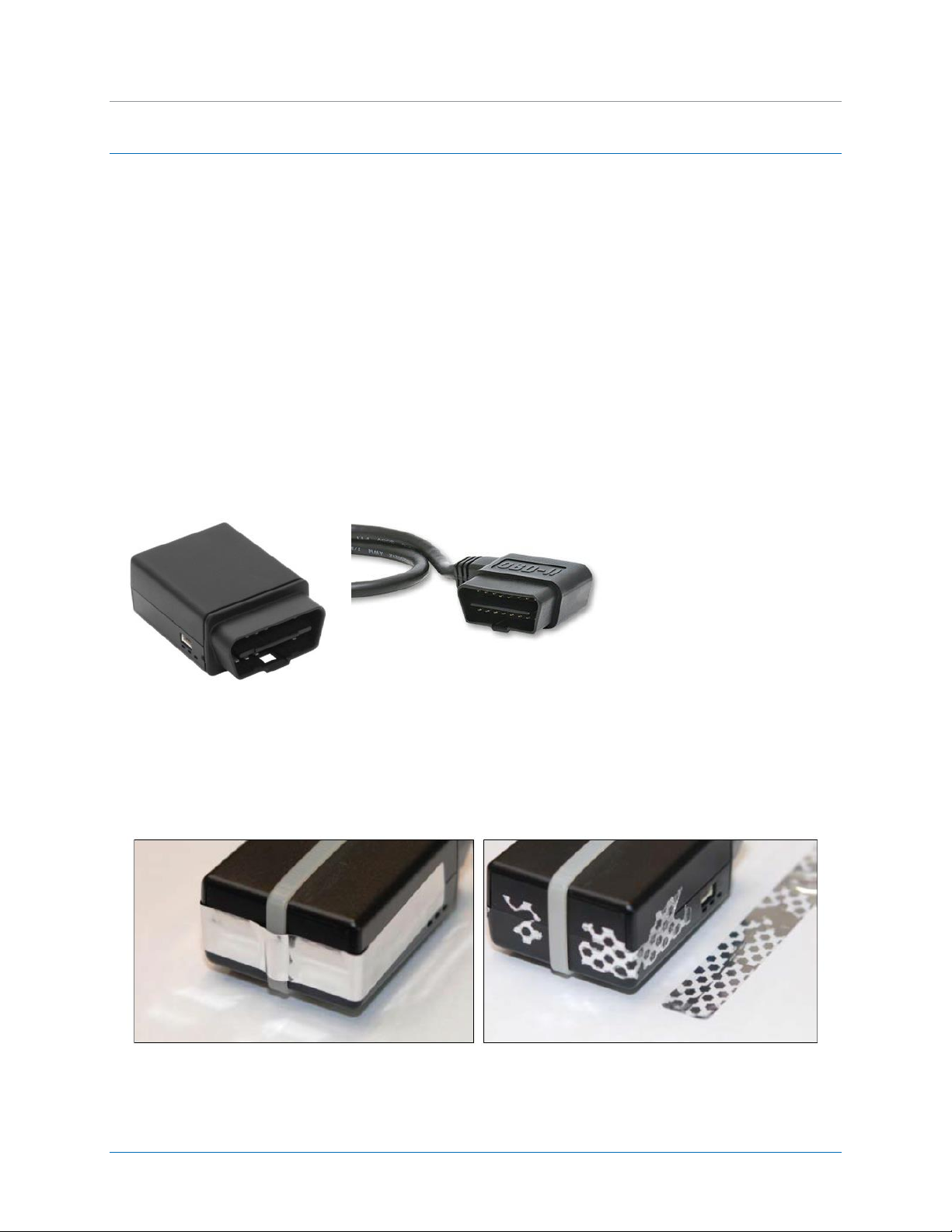
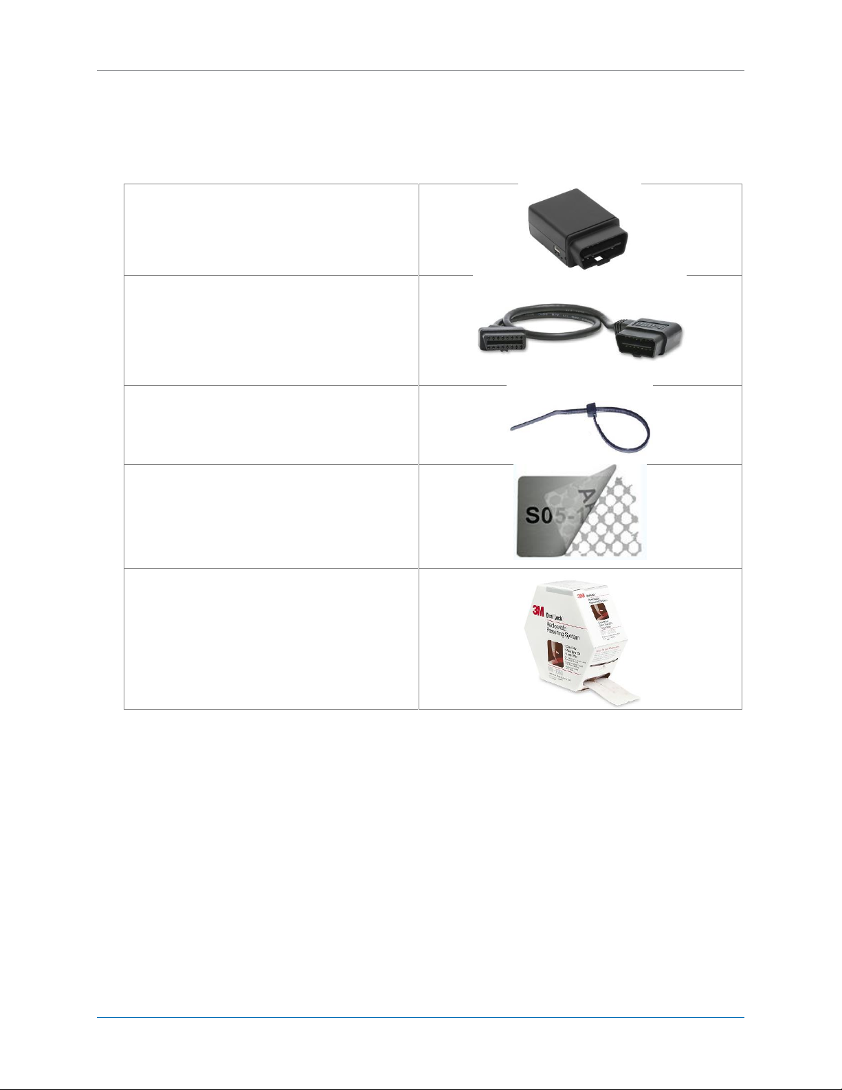
CalAmp | LMU-30xx/CVF-3030 & OBD-II Extender Cable Install
Guide
MBUD-0268v1.4 Page 1
1 REGULATORY INFORMATION
1.1 Human Exposure Compliance Statement
Pursuant to 47 CFR § 24.52 of the FCC Rules and Regulations, personal communications services (PCS)
equipment is subject to the radio frequency radiation exposure requirements specified in § 1.1307(b), §
2.1091 and § 2.1093, as appropriate.
CalAmp certifies that it has determined that the LMU-30xx/CVF-3030 complies with the RF hazard
requirements applicable to broadband PCS equipment operating under the authority of 47 CFR Part 24,
Subpart E of the FCC Rules and Regulations. This determination is dependent upon installation,
operation and use of the equipment in accordance with all instructions provided.
The LMU-30xx/CVF-3030 is designed for and intended to be used in fixed and mobile applications.
“Fixed” means that the device is physically secured at one location and is not able to be easily moved to
another location. “Mobile” means that the device is designed to be used in other than fixed locations
and generally in such a way that a separation distance of at least 20 cm is normally maintained between
the transmitter’s antenna and the body of the user or nearby persons. The LMU-26xx is not designed for
or intended to be used in portable applications (within 20 cm of the body of the user) and such uses are
strictly prohibited.
To ensure that the LMU-30xx/CVF-3030 complies with current FCC regulations limiting both maximum
RF output power and human exposure to radio frequency radiation, a separation distance of at least 20
cm must be maintained between the unit’s antenna and the body of the user and any nearby persons at
all times and in all applications and uses. Additionally, in mobile applications, maximum antenna gain
must not exceed 3 dBi.
1.2 Hardware Precautions
Electrical Over-Stress (EOS)
The LMU-30xx/CVF-3030 GPS receiver can be damaged if exposed to an RF level that exceeds its
maximum input rating. Such exposure can happen if a nearby source transmits an RF signal at
sufficiently high level to cause damage.
Storage and Shipping
One potential source of EOS is proximity of one LMU-30xx/CVF-3030 GPS Antenna to another LMU-
30xx/CVF-3030 GSM Antenna. Should one of the units be in a transmit mode, the potential exists for the
other unit to become damaged. Therefore, any LMU-30xx/CVF-3030 should be kept at least four inches
apart from any active LMU-30xx/CVF-3030 or any other active high power RF transmitter with power
greater than 1 Watt.