CalAmp LMU-26xx User manual

CalAmp Corp.
13645 Dulles Technology Drive, Herndon, VA 20171 Document: MBUD-0199v3.3
Phone: 703. 262.0500 November 2014
Fax: 703.262.0380
www.calamp.com
LMU-26xxTM Install Guide

CalAmp | LMU-26xx Install Guide
Page ii MBUD-0199v3.3
CalAmp | LMU-26xxTM Install Guide
Copyright © 2013 CalAmp Corporation. All rights reserved.
Printed in the United States of America.
All trademarks used are properties of their respective owners.
Products offered may contain software proprietary to CalAmp or other parties. The offer of supply
of these products and services does not include or infer any transfer of ownership. No part of the
documentation or information supplied may be divulged to any third party without the express
written consent of CalAmp.
CalAmp reserves the right to modify the equipment, its specification or this manual without prior
notice, in the interest of improving performance, reliability, or servicing. At the time of publication
all data is correct for the operation of the equipment at the voltage and/or temperature referenced.
Performance data indicates typical values related to the
particular product.
Product updates may result in differences between the information provided in this manual and the
product shipped. We have made every effort to ensure the accuracy of all information contained in
this document; however, CalAmp makes no expressed or implied warranty or representation based
upon the enclosed information.
Revision History:
Version #
Revision Date
Author
Details
1.0
3/2/2011
Marketing
Baseline release
1.1
5/7/2011
Marketing
Unit information revised
1.2
3/27/2012
Product
Instruction for install in weather exposed
environments
2.0
4/24/2013
ABP
Revised style and device name.
3.0
1/30/2014
ABP
Added Buzzer, LED, jPOD and vPOD instructions.
3.1
2/10/14
ABP
Updated P/N for standard wiring harness
3.2
8/11/2014
Allen Frederick
Added sections 3.1 & 3.2 showing various wiring
harness and accessories. Updated installation
instructions for JPOD and VPOD. Added instructions
for new JPOD/VPOD wiring harness 5C261.
3.3
11/4/2014
Product
Revised and updated jPOD and vPOD
Added Privacy switch wiring

CalAmp | LMU-26xx Install Guide
MBUD-0199v3.3 Page iii
TABLE OF CONTENTS
1REGULATORY INFORMATION .....................................................................................1
1.1 HUMAN EXPOSURE COMPLIANCE STATEMENT .................................................................................. 1
1.2 HARDWARE PRECAUTIONS............................................................................................................. 1
2INTRODUCTION..........................................................................................................2
2.1 GUIDE PREREQUISITES .................................................................................................................. 2
3LMU-26XX OVERVIEW ................................................................................................3
3.1 AVAILABLE WIRING HARNESS......................................................................................................... 4
3.2 ACCESSORIES............................................................................................................................... 5
3.3 ENVIRONMENTAL SPECIFICATIONS .................................................................................................. 6
4PRE-INSTALLATION CONSIDERATIONS ........................................................................7
4.1 PLAN THE INSTALLATION ............................................................................................................... 7
4.2 SIZE AND PLACEMENT OF LMU-26XX.............................................................................................. 7
4.3 PROTECTION FROM HEAT .............................................................................................................. 8
4.4 VISIBILITY OF DIAGNOSTIC LEDS..................................................................................................... 8
4.5 CABLE LENGTH ............................................................................................................................ 8
4.6 MOISTURE AND WEATHER PROTECTION .......................................................................................... 9
4.7 PREVENTING ACCIDENTAL OR UNAUTHORIZED MODIFICATION ............................................................ 9
5LMU-26XX INSTALLATION.........................................................................................10
5.1 SELECT THE LOCATION FOR THE LMU-26XX AND INSTALL IT............................................................. 11
5.1.1 Under Dash Installation.................................................................................................. 12
5.1.2 Installation in exposed area ........................................................................................... 15
5.2 INSTALL POWER CONNECTIONS ............................................................................................ 15
5.2.1 Secure All Cables ............................................................................................................ 20
5.3 OPTIONAL BUZZER ASSEMBLY CABLE............................................................................................. 21
5.4 OPTIONAL SWITCH WITH LED CABLE WITH BUZZER.......................................................................... 22
5.5 CONNECT OPTIONAL INPUTS................................................................................................. 23
5.6 INSTALL OPTIONAL SERIAL CABLES........................................................................................ 24

CalAmp | LMU-26xx Install Guide
Page iv MBUD-0199v3.3
5.6.1 Serial/Host/AUX 1 .......................................................................................................... 25
5.6.2 Serial/AUX 2 –Garmin Serial Cable................................................................................ 26
5.6.3 Serial/AUX2 –jPOD Adapter and jPOD Cable ................................................................ 27
5.6.4 Serial/AUX 2 –vPOD Adapter......................................................................................... 30
5.6.5 Privacy Switch................................................................................................................. 33
5.6.6 Secure All Cables ............................................................................................................ 34
5.7 VERIFY LMU-26XX OPERATIONS .................................................................................................. 35
5.7.2 STATUS LEDS .................................................................................................................. 35
5.7.3 COMM Verification ........................................................................................................ 36
5.7.4 GPS Verification.............................................................................................................. 36
5.7.5 Inbound Verification ...................................................................................................... 36
5.8 GUIDELINES FOR TROUBLESHOOTING COMMON PROBLEMS .............................................................. 37
6DE-INSTALLATION INSTRUCTIONS.............................................................................38
7WARRANTY..............................................................................................................39
APPENDIX A –LMU-26XX ACCESSORY CABLES AND PIGTAIL WIRING INSTRUCTIONS .......40
PRIMARY CONNECTOR ........................................................................................................................... 40
LMU-26XX –FULL I/0 WIRING HARNESS –P/N 5C908 ............................................................................ 42
LMU-26XX -SERIAL ADAPTER ................................................................................................................ 43
7.1 BUZZER AND CABLE ASSEMBLY –P/N 4C765 ................................................................................ 44
7.2 GARMIN TO 5-PIN SERIAL CABLE –P/N 133688 ............................................................................ 44
7.3 JPOD ADAPTER –P/N 134152-JPOD......................................................................................... 45
7.4 VPOD 5-PIN SERIAL OBD-II ADAPTER –P/N 133917 ................................................................... 45
8CUSTOMER SUPPORT CONTACT INFORMATION........................................................46

CalAmp | LMU-26xx Install Guide
MBUD-0199v3.3 Page v
LIST OF FIGURES
Figure 1: CalAmp LMU-26xx Device....................................................................................................... 3
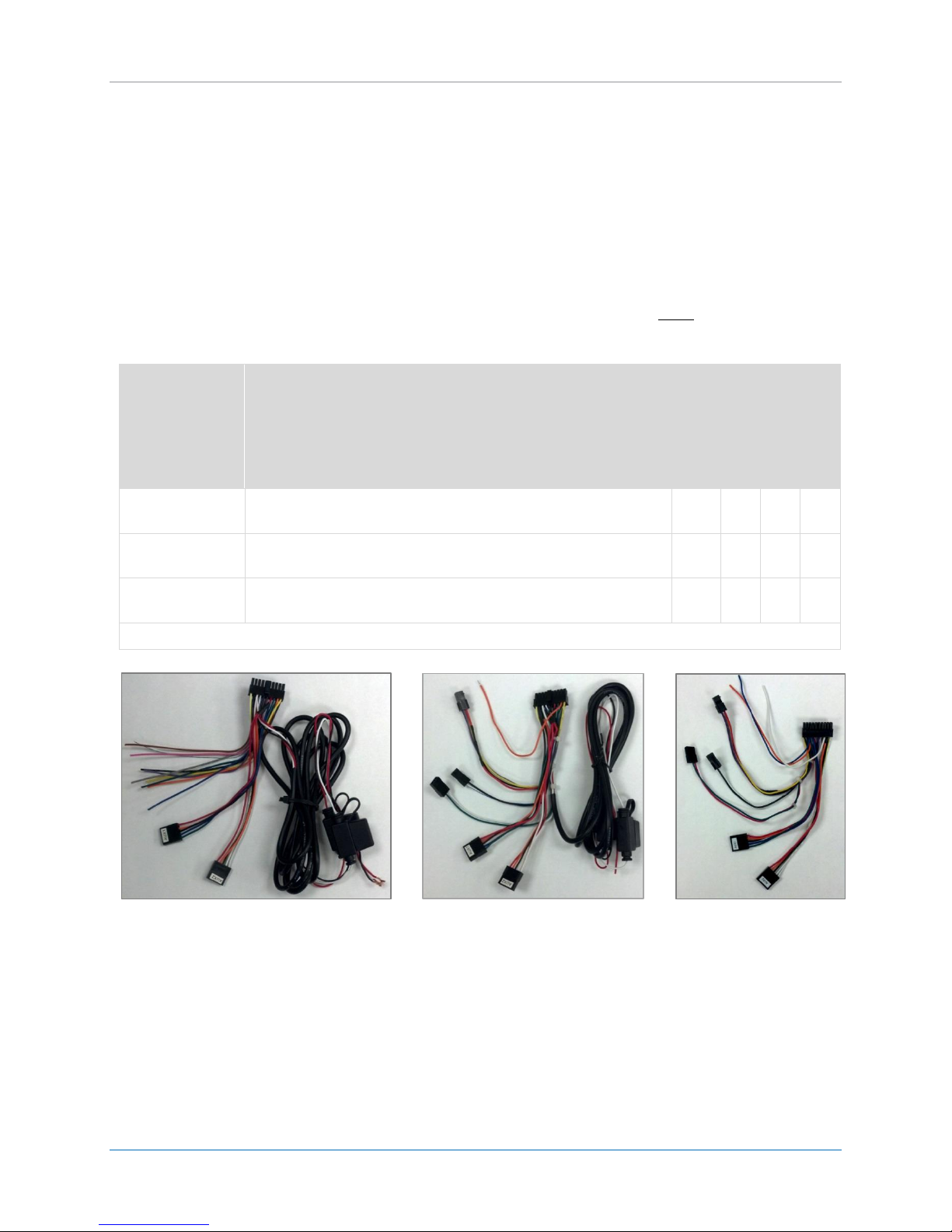
Figure 2: P/N 5C260 No jPOD/vPOD Accessories.................................................................................. 4
Figure 3: P/N 5C908 No jPOD/vPOD Accessories.................................................................................. 4
Figure 4: P/N 5C261 jPOD or vPOD........................................................................................................ 4
Figure 5: Coil Excess Cable ..................................................................................................................... 8
Figure 6: Tamper Resistant Materials .................................................................................................... 9
Figure 7: LMU-26xx Under Dash Mount .............................................................................................. 12
Figure 8: Re-closable Fastener Tape on LMU-26xx.............................................................................. 13
Figure 9: Re-closable Fastener Tape - Prior to Mounting .................................................................... 13
Figure 10: LMU-26xx Standard Wiring Harness (P/N: 5C908) ............................................................. 15
Figure 11: Power Leads........................................................................................................................ 16
Figure 12: Ring Connector on Ground Wire......................................................................................... 17
Figure 13: Ground Connection............................................................................................................. 17
Figure 14: Main Vehicle Wire Harness................................................................................................. 18
Figure 15: Ignition Wires...................................................................................................................... 18
Figure 16: Wrapped Fuse Lead ............................................................................................................ 19
Figure 17: Applied Torque Seal............................................................................................................ 19
Figure 18: Secured Cables.................................................................................................................... 20
Figure 19: Connect Buzzer Assembly to the LMU-26xx Power Accessory Cable 5C260 or 5C261 ...... 21
Figure 20: LMU-26xx Buzzer Assembly Connected.............................................................................. 21
Figure 21: Connect Switch with LED cable to LMU-26xx Power Accessory Cable ............................... 22
Figure 22: LMU-26xx Switch/LED Assembly Connected ...................................................................... 22
Figure 23: LMU-26xx Connectors......................................................................................................... 23
Figure 24: LMU-26xx Standard Wiring Harness and Connectors......................................................... 24
Figure 25: LMU-26xx DB9 Serial Connection ....................................................................................... 25
Figure 26: LMU-26xx DB9 Serial Connection ....................................................................................... 25
Figure 27: LMU-26xx and Garmin PND Cable Connection................................................................... 26
Figure 28: jPOD Adapter (PN: 134152) Figure 29: jPOD Cable (PN: 5C909-2) .............................. 27
Figure 30: 6-pin j1708 Cable. (PN: 8973002002) Figure 31: 9 PIN JBUS J1936 TO 6 PIN J1708
ADAPTER CABLE (PN:8973002001)............................................................................................... 27
Figure 32: AUX2 Connection ................................................................................................................ 28
Figure 33: Connect jPOD Cable and jPOD Adapter Using Serial Connector......................................... 29
Figure 34: LMU-26xx and jPOD Assembly............................................................................................ 29
Figure 35: vPOD Adapter (133917-VPOD) ........................................................................................... 30
Figure 36: AUX2 Connection ................................................................................................................ 31
Figure 37: vPOD With Harness 5C261 Figure 38: vPOD With Harness 5C260 or 5C908 .................. 32
Figure 39: vPOD Adapter and Vehicle OBD-II Port............................................................................... 32
Figure 40 - DPST switch diagram.......................................................................................................... 33
Figure 41 –Example illuminated rocker switch ................................................................................... 33
This manual suits for next models
1
Table of contents