CALECTRO Uniguard 8 User manual

Calectro AB Phone: +46 31-69 53 00 info@calectro.se www.calectro.se
Installation instruction
Uniguard 8
Hydraulic diameter ( )
Example of installation at
sources of interference:
- fan
- damper
- silencer
- battery
- air handling unit
- duct bend
- duct branching
- duct narrowing or expansion
Where large temperature variations
occur, e.g. on outdoor
locations or in areas subject to
outside temperatures (roof,
attics), the Uniguard should be
insulated, see para 8.
Note the foot’s shape of an arrow, which shall be installed towards the air flow direction.
Example of location after
change of duct direction.
Example of location before
a ventilation grill.
Ventilation grill
Airflow direction
5 dh3 dh
© 2023.10.03 R1.0 Calectro AB
d = D
Ø D
hd =
h2xHxB
H+B H
B
Hydraulic diameter
MIN 3xdhMIN 5xdh
UG8 UG8
FAN
MIN 5xdh
UG8
MIN 3xdh
UG8
DUCT BEND
UG8
MIN 5xdh
UG8
MIN 3xdh
UG8
MIN 3xdh
DUCT BRANCHING
UG8
UG8
MIN 3xdh
MIN 5xdh
AIR HANDLING UNIT
RETURN AIR
INLET AIR
RECTANGULAR DUCT
CIRCULAR DUCT
MIN 3xdhMIN 5xdh
GX GX
MIN 3xdhMIN 5xdh
GX GX
MIN 3xdhMIN 5xdh
GX GX
MIN 3xdhMIN 5xdh
GX GX
MIN 3xdhMIN 5xdh
GX GX
MIN 5xdh
GX
MIN 3xdh
GX
MIN 5xdh
GX
MIN 3xdh
GX
GX MIN 3xdh
GX
GX
MIN 3xdh
MIN 5xdh
d = D
Ø D
h
d =
h
2xHxW
H+W H
W
Hydraulic diameter
Example of location
FRÅNLUFT / RETURN AIR
TILLUFT / INLET AIR
RECTANGULAR DUCT
CIRCULAR DUCT
CIRCULAR DUCT
RECTANGULAR DUCT
h
d
ENGLISH
Mounting and positioning
The Uniguard should be installed according to the
drawing below. The Uniguard can be installed on any
side of the duct.
We recommend that the Uniguard is mounted at an
equal distance from sources of interferance, and similar
to the siting of flow monitors.
A distance of 3 times the duct hydraulic diameter should
be left before a source of interferance, and 5 times the
hydraulic diameter after.
UG8-E models

2
1
2
3
Drill a hole in the duct
Cut the venturi sampling tube
1. Measure the diameter of the duct.
2. The tube should penetrate at least 90% of
the width of the duct. NOTE! See para 3.
3. Shorten the sampling tube, if necessary.
4. Insert the end plug.
Fitting of tubes in ducts with different diameters
Shorten the tube to correct length.
Insert the end plug.
Put on the end plastic
gasket.
Put on the rubber
gasket, HFU204.
NOTE!
Drill a hole
Ø 51 mm (2").
ST-EXTEND
Drill a hole
Ø 38 mm (1,5")
Drill a hole
Ø 38 mm (1,5")
Max diameter of the duct 600 mm (2 ft).
Use the venturi tube 280 or
580 mm (1 or 2 ft).
Shorten the tube, if necessary.
For ducts with a ø of less than 0,6 m use the 0,6 m pipe.
For ducts with a ø of between 0,6 m and 1,4 m use the 1,5 m pipe.
For ducts which are larger than 1,4 m use the 2,8 m pipe.
The venturi tube shall not
protrude more than 30 mm (1")
through the duct wall.
Diameter of the duct larger
than 600 mm (2 ft).
The venturi tube should penetrate
the whole duct. Extend with
one or more extention tubes.
For ducts up to 300 mm (1 ft), use ST280.
For ducts between 300-600 mm (1-2 ft), use ST580.
For ducts over 600 mm (2 ft), extend the tube with
ST-EXTEND.
When using ST-EXTEND, the tube must always be attached
to the opposite duct wall, together with rubber gasket HFU204.
If strong vibrations occur in the venturi tube, we recommend
stabilizing the tube further, e.g. with mounting strap.
2
1
3
4
≥ 90%
100%
9
ø 38 mm (1,5") ø 51 mm (2")
Ø > 200 mm (2/3 ft)
1. For all ducts larger than 200 mm (2/3 ) hydralic diameter,
the UG8 can be mounted directly on the duct.
2. If the duct is insulated or smaller than 200 mm (2/3 ),
use mounting bracket UG-MB-8.
1
2
3
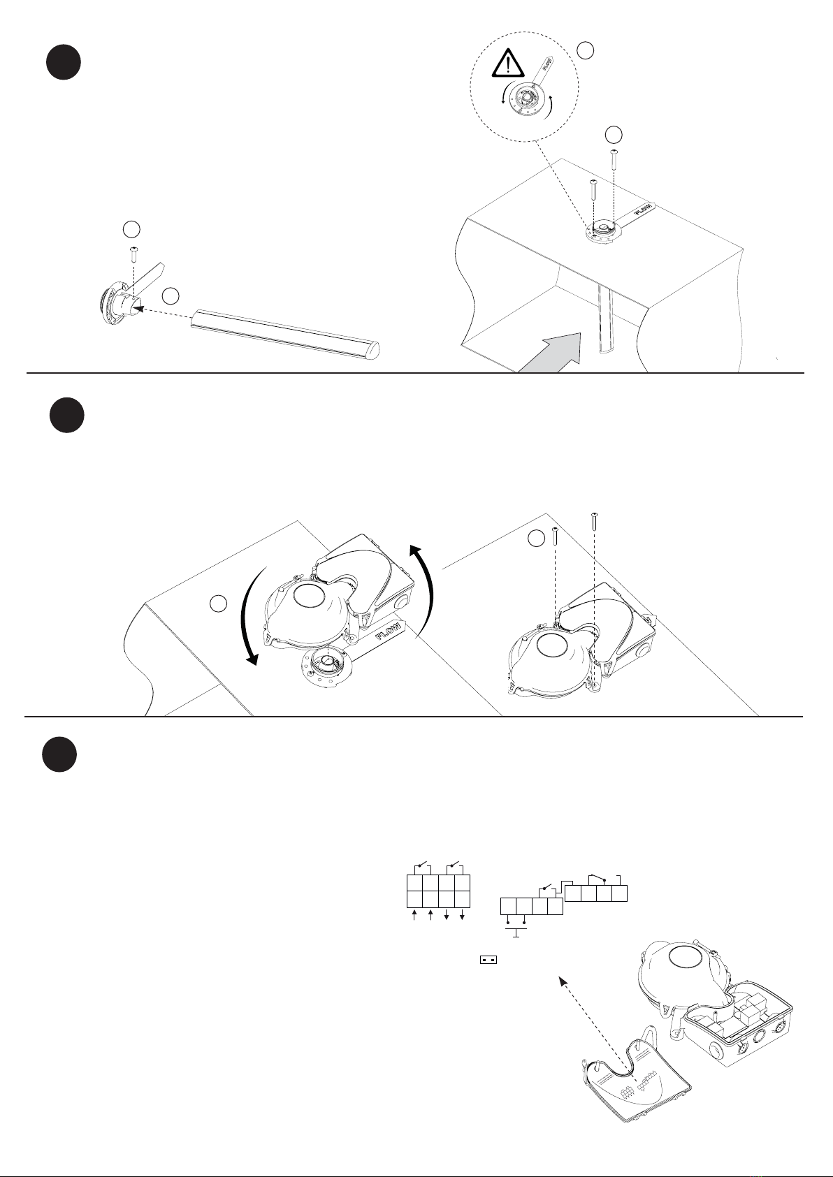
1. Mount the Uniguard on the rotation part and
rotate it to the desired direction.
2. Secure the Uniguard with the two screws.
Installation on the duct
5
4Mount the sampling tube and the rotation part
1. Insert the sampling tube into the bottom
of the rotation part.
2. Secure the tube with the locking screw.
3. Turn the rotation part in the correct air-flow direction,
so that the white FLOW-arrow and the air-flow
direction of the duct correlate.
4. Fix the rotation part to the ventilation duct
according to the illustration.
3
4
2
1
2
1
360°
6
1. Gently remove the cover over the connection
housing by releasing the snap locks. Uniguard 8
has two pre-mounted IP67 approved glands for
cable diameter 4-11 mm, type Klikseal.
NOTE! The cable must only be pulled through
the Klikseal in one direction: into the Uniguard.
To exchange a mounted cable, cut the cable
outside of the Uniguard and pull out the rest
from the inside.
2. Connect the cable wires according to the
wiring diagram on the inside of the cover of the
connection chamber.
UG8-E-24: 24V AC/DC
UG8-E-230: 230V AC
The relay outputs are shown in power off/alarm
condition. For complete technical product
information, see the product data sheet.
Electrical installation
12
11
10
9
16
15
14
13
12 3 4
8
7
6
5
Smoke alarm relay 2
Reset
Jumper
12
11
10
9
16
15
14
13
12 3 4
8
7
6
5
C NC C NC
NO NCC
Relay System failure
G0 -
G0 -
Power supply +
Power supply +
Relay Service alarm*
1
Contamination/Low flow
Smoke alarm relay 1
NC C C
*2
*1 Service alarm can indicate either low airflow or contimination.
*2 Jumper ON disables air flow monitoring.
A
i
r
f
l
o
w
D
i
r
e
c
t
i
o
n

4
Mounting in places where possible condensation problems could arise, e.g. cold attics.
Use protection cover e.g. Calectro´s
UG-COVER-75.
Use insulation cover of 100-200 mm (4-8")
to protect the entire Uniguard.
8
Do not drill any holes in the cover for signs etc.
Holes will cause air leakage and seriously disturb
the function of the detector.
Test of detector
7
T
E
ST
SP
R
AY
1. Check the detector with smoke detector
aerosol test spray (e.g. SOLO A5).
2. Move the "test hole plug" to the side
and briefly release a spray of aerosol.
When alarming, the LED lits red on the
detector and when service alarming
(contamination) it lits green.
IMPORTANT!
Reassemble the "test hole plug".
A sign should be used to show location of the detector.
A remote LED alarm indication is recommended when the Uniguard is hidden.

5
9Mounting bracket for insulated ducts and ducts smaller than 200 mm (2/3 ft).
Shape the mounting bracket in position A or B. The mounting bracket can then
easily be bent to t circular or rectangular ducts.
The position of the legs of the mounting bracket will be locked with the mounting
screws from the rotation part.
The mounting bracket is supplied at.
Fix the bracket
on to the duct.
A B
Turn the mounting bracket in the correct aiflow direction.

Calectro AB Phone: +46 31-69 53 00 info@calectro.se www.calectro.se
1. Remove the cover by gently bending
the snap locks outwards.
4. Insert the new detector and
rotate it clockwise.
2. Detach the cover.
5. Reattach the cover. (1) Start by
placing the “lip” of the cover in
the cavity next to the air inlet.
(2) Then press down the cover.
3. Remove the smoke detector
by rotating it contraclockwise
approximately 1/5 turn.
6. Check that all three snap
locks are properly pressed
in place.
2
1
According to WEEE (Waste of Electrical and Electronic Equipment) directive, you must at the end of life of the product dispose of it separately at an
appropriate collection point and not place it with unsorted waste. Alternatively return it to Calectro for recycling.
FINAL CHECKS
• Check that the rotation part of the Uniguard is correctly
installed according to the air flow in the duct.
• Check that the plastic plug of the test hole is properly
installed.
• It is recommended that smoke from a smoke generator is
introduced into the duct to check the detector’s function.
Trouble shooting
The smoke detector indicates alarm without smoke.
• Smoke detector is faulty or contaminated. The detector needs to be
replaced.
In case you need to replace the smoke detector
10
This manual suits for next models
3
Table of contents


