Selectable systems
Characteristics
+
– +
SET
!
Ì
"
"
F
R
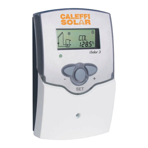
System screen LCD display
with 16-segment display and
8 symbols for system status
Operating LED control lamp
3 push-button controls
Attractive design and compact
dimensions
Easy to install
User-friendly operation
S1
S2
S4 / TRL
R1
S3
S1
S3
S4
R1
R2
S2
Tank 1
Tank 2
R2
S1
S2
R1 S3
S4 / TRL
R2
S4 / TRL
S1
R1
S2 S3
Tank 1 Tank 2
S1
S2 S3
R1 R2
Tank 1 Tank 2
S4 / TRL
R1
R2
S1
S2
S3 S1
S4
S2
S3
R1
R2
S1
S3
S2
S4
R2
R1
Standard system with 1 tank, 1 pump and 3
sensors. S4 / TRF can be used as BTU meter
System and heat exchange with an existing
tank with 1 tank, 4 sensors and 2 pumps
Solar system and backup heating with 1 tank, 3
sensors. S4 / TRF can be used as BTU meter
2-tank-solar system with valve logic, 3
sensors, 1 solar pump and 3-way valve.
Sensor S4 / TRF can used as BTU meter
2-tank solar system with pump logic, 3
sensors and 2 solar pumps
Solar system with east-west collectors,
1 tank, 3 sensors and 2 solar pumps.
System with backup heating by wood boiler
with 1 tank, 4 sensors, 1 solar pump and
1 pump for backup heating.
System and heating circuit pre-heat with
1 tank, 4 sensors, 1 solar pump and 3-way
valve for heating circuit.
S2
R1
S3
R2
S1
S4 / TRL
System and tank charge in layers with 1 tank,
3 sensors, 1 solar pump and 3-way valve.
Sensor S4 / TRF can be used as BTU meter
R2
S1
S2
R1 S3
S4 / TRL
Solar system and heat dumping with 1 tank, 3
sensors. S4 / TRF can be used as BTU meter
iSolar 1 iSolar 2 iSolar 3 iSolar Plus
Electronic relayy0102
Standard relay 1 0 2 0
Pump speed control no yes no yes
Operating hours counter yes yes yes yes
kWh (BTU) measurement yes yes yes yes
V-bus for data recorder yes yes yes yes
PC-interface RS232 yes yes yes yes
Heat dumping function no no yes yes
Backup heat function no no yes yes
Additional ΔT control no no no yes
Two-tank priority no no no yes
Clock with scheduling no no no yes
A062752A013752A022752A012752edoC
Selectable programs 1 1 2 9
S
tandard operation functions
∆T control - When the switch-on difference is reached, the pump is activated until
the differential temperature drops below.
Maximum tank temperature - When the adjusted maximum tank temperature is
exceeded, the pump switches off.
Collector emergency shutdown - If adjusted collector temperature is exceeded,
the solar pump is switched off.
System cooling - If the temperature rises to the maximum collector temperature
the solar pump remains on until this temperature drops.
Minimum collector temperature - a minimum set temperature which must be
exceeded before the solar pump is switched-on.
Antifreeze function - If the adjusted temperature drops, the solar pump is switched
on to protect the fluid from freezing.
Tank cooling function - In the evening, the solar pump continues running until
the storage tank is cooled down.
Tube collector function - The controller measures an increase of heat rise in the
collector and adjusts operating time for maximum efficiency.
Heat generation measurement kWh (BTU) - The heat generated is measured by
the volume flow and the temperature of feed and return sensors.
Operating hours counter - Operating hours counter stores the solar operating
hours of the respective relay.
Manual operating mode - For control and servicing, the operating mode of the
controller can be switched manually.
Heat dumping function - Heat dumping function works independently from the
solar operation and activates the second relay.
Backup heating function - Backup heating function works independently from
the solar operation and activates the second relay.
Second independent ∆T control - The switch on and off temperatures can be
adjusted separately.
Priority tank / tank rotation - The controller checks the tank temperatures and
rotates or gives priority to charging tanks.
East / West collectors - Two separate ∆T controls activate each solar pump
based on collectors and the one-tank differential temperature.
Advanced operation functions (some two-relay models)
Pump speed control functions
Pump speed control can improve system efficiency by reducing the flow to
the collectors on cloudy days to improve solar thermal transfer and reduce
electrical consumption. This is achieved by the differential temperature
value between the collectors and storage tank.
If the value for the ΔT switch-on is reached (e.g. ΔT on = 9º ), the pump
will start with 100% pump speed for 10 seconds, then reduce the speed to
the adjusted minimum pump speed (min. pump speed = 30 %, adjustable).
If the temperature difference reaches the set value (e.g. ΔT Set = 18º ),
pump speed will increase by 10 %. At any further rise of 3º ΔT the pump
speed will increase by 10% until the maximum of 100% is reached.
Model selection


