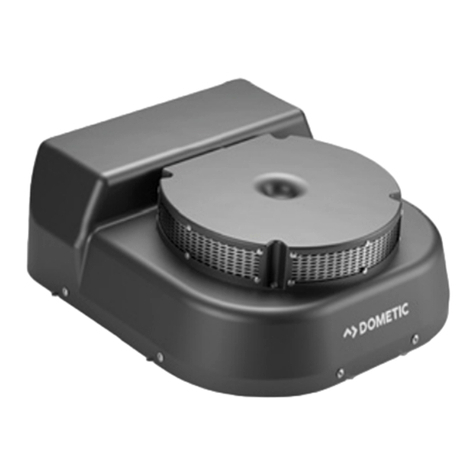
Dometic Frigo Series User manual

CLIMATE CONTROL
FRIGO
Frigo DC 2500, Frigo DC 3500
Electrical transport refrigeration
system
Installation Manual . . . . . . . . . . . . . . . . . .17
Elektrische Transportkühlanlage
Montageanleitung . . . . . . . . . . . . . . . . . 43
Système électrique de
refroidissement pour le transport
Instructions de montage. . . . . . . . . . . . . 70
Elektrisch mobiel koelsysteem
Montagehandleiding . . . . . . . . . . . . . . . 98
EN
DE
FR
NL
Frigo_DC-I-West.book Seite 1 Mittwoch, 24. Juni 2020 11:27 11

© 2020 Dometic Group. The visual appearance of the contents of this manual is protected by
copyright and design law. The underlying technical design and the products contained herein may
be protected by design, patent or be patent pending. The trademarks mentioned in this manual
belong to Dometic Sweden AB. All rights are reserved.
Frigo_DC-I-West.book Seite 2 Mittwoch, 24. Juni 2020 11:27 11

Frigo DC
2
3
4
21
1
Frigo DC 2500
2
7
1
3
5
15
4
6
89
10
11
12
13
14
2
Frigo_DC-I-West.book Seite 2 Mittwoch, 24. Juni 2020 11:27 11

3
Frigo DC
Frigo DC 3500
2
7
1
3
5
4
6
89
10
11
12
13
15
14
3
475 8
1
2
9
3
6
4
Frigo_DC-I-West.book Seite 3 Mittwoch, 24. Juni 2020 11:27 11

Frigo DC
4
35 mm
60 mm
170 mm
24 mm
80 mm
5
2 2 2 2 2 2 2
1
6
Frigo_DC-I-West.book Seite 4 Mittwoch, 24. Juni 2020 11:27 11

5
Frigo DC
80 mm
20 mm
20 mm
377 mm
591 mm
4,5 mm
Ø
1
Frigo DC 2500
7
80 mm
20 mm
20 mm
377 mm
840 mm
4,5 mmØ
1
Frigo DC 3500
8
Frigo_DC-I-West.book Seite 5 Mittwoch, 24. Juni 2020 11:27 11

Frigo DC
6
9
P
1234
76
35
56 3
28
0
Frigo_DC-I-West.book Seite 6 Mittwoch, 24. Juni 2020 11:27 11

7
Frigo DC
71 mm
29 mm
a
60 mm
60 mm
20 mm
M4 x 16
3,9 x 9,5
M4
b
1
2
c
Frigo_DC-I-West.book Seite 7 Mittwoch, 24. Juni 2020 11:27 11

Frigo DC
8
A
C
DE
FG
B
d
Frigo_DC-I-West.book Seite 8 Mittwoch, 24. Juni 2020 11:27 11

9
Frigo DC
13/32“
5/16“
5/16“
1/2“
5/16“
1/2“
1
2
7
8
4
5
3
6
e
Frigo_DC-I-West.book Seite 9 Mittwoch, 24. Juni 2020 11:27 11

Frigo DC
10
f
AC INPUT
12345
STATUS TEMP/LIN1 LIN2
1234
DCOUTPUT
g
Frigo_DC-I-West.book Seite 10 Mittwoch, 24. Juni 2020 11:27 11

11
Frigo DC
h
Ø 80 mm
i
Frigo_DC-I-West.book Seite 11 Mittwoch, 24. Juni 2020 11:27 11

Frigo DC
12
2.
1.
j
2.
3.
1.
4.
k
Frigo_DC-I-West.book Seite 12 Mittwoch, 24. Juni 2020 11:27 11

13
Frigo DC
Frigo DC 3500Frigo DC 2500
l
m
Frigo_DC-I-West.book Seite 13 Mittwoch, 24. Juni 2020 11:27 11

Frigo DC
14
A
B
n
2.
3.
1.
o
Frigo_DC-I-West.book Seite 14 Mittwoch, 24. Juni 2020 11:27 11

15
Frigo DC
p
Ø3 mm
Ø24 mm
230 V
10
31 4
5
9
11
8
2
6
7
q
Frigo_DC-I-West.book Seite 15 Mittwoch, 24. Juni 2020 11:27 11

17
EN
Frigo DC
Original instructions
Please read this manual carefully before starting the device. Keep it in
a safe place for future reference. If the device is passed on to another
person, this manual must be handed over to the user along with it.
The manufacturer cannot be held liable for damage resulting from
improper usage or incorrect operation.
Table of contents
1 Explanation of symbols . . . . . . . . . . . . . . . . . . . . . . . . . . . . . . . . . 18
2 Safety instructions . . . . . . . . . . . . . . . . . . . . . . . . . . . . . . . . . . . . . 18
2.1 General safety. . . . . . . . . . . . . . . . . . . . . . . . . . . . . . . . . . . . . . . . . . . . . . . . . . . . 19
2.2 Safety during installation . . . . . . . . . . . . . . . . . . . . . . . . . . . . . . . . . . . . . . . . . . . 20
3 Target group for this instruction manual . . . . . . . . . . . . . . . . . . . 20
4 Intended use . . . . . . . . . . . . . . . . . . . . . . . . . . . . . . . . . . . . . . . . . . 20
5 Scope of delivery . . . . . . . . . . . . . . . . . . . . . . . . . . . . . . . . . . . . . . 21
5.1 Frigo DC 2500 . . . . . . . . . . . . . . . . . . . . . . . . . . . . . . . . . . . . . . . . . . . . . . . . . . . 21
5.2 Frigo DC 3500 . . . . . . . . . . . . . . . . . . . . . . . . . . . . . . . . . . . . . . . . . . . . . . . . . . . 23
5.3 Stationary cooling (optional) . . . . . . . . . . . . . . . . . . . . . . . . . . . . . . . . . . . . . . . . 24
6 Accessories . . . . . . . . . . . . . . . . . . . . . . . . . . . . . . . . . . . . . . . . . . . 25
7 Installing the transport refrigeration system . . . . . . . . . . . . . . . 25
7.1 Prerequisites for the installation . . . . . . . . . . . . . . . . . . . . . . . . . . . . . . . . . . . . . . 25
7.2 Installation instructions. . . . . . . . . . . . . . . . . . . . . . . . . . . . . . . . . . . . . . . . . . . . . 25
7.3 Checking installation conditions . . . . . . . . . . . . . . . . . . . . . . . . . . . . . . . . . . . . . 28
7.4 Installing the DC unit . . . . . . . . . . . . . . . . . . . . . . . . . . . . . . . . . . . . . . . . . . . . . . 28
7.5 Installing the evaporator. . . . . . . . . . . . . . . . . . . . . . . . . . . . . . . . . . . . . . . . . . . . 28
8 Installing the control unit. . . . . . . . . . . . . . . . . . . . . . . . . . . . . . . . 29
8.1 Installing in the dashboard. . . . . . . . . . . . . . . . . . . . . . . . . . . . . . . . . . . . . . . . . . 29
8.2 Installing the console . . . . . . . . . . . . . . . . . . . . . . . . . . . . . . . . . . . . . . . . . . . . . . 30
9 Connecting the transport refrigeration system . . . . . . . . . . . . . 30
9.1 Standard tightening torques . . . . . . . . . . . . . . . . . . . . . . . . . . . . . . . . . . . . . . . . 30
9.2 Information about installing O-ring fittings . . . . . . . . . . . . . . . . . . . . . . . . . . . . . 30
9.3 Information about installing the fittings . . . . . . . . . . . . . . . . . . . . . . . . . . . . . . . . 31
9.4 Wiring diagrams . . . . . . . . . . . . . . . . . . . . . . . . . . . . . . . . . . . . . . . . . . . . . . . . . . 32
9.5 Connecting components to the refrigeration and electrical systems . . . . . . . . 34
10 Installation of stationary cooling (optional) . . . . . . . . . . . . . . . . 36
10.1 Installing battery charger . . . . . . . . . . . . . . . . . . . . . . . . . . . . . . . . . . . . . . . . . . . 36
10.2 Installing device socket . . . . . . . . . . . . . . . . . . . . . . . . . . . . . . . . . . . . . . . . . . . . 37
10.3 Connecting stationary cooling . . . . . . . . . . . . . . . . . . . . . . . . . . . . . . . . . . . . . . 38
10.4 Connecting 230 V voltage in the interior . . . . . . . . . . . . . . . . . . . . . . . . . . . . . . 38
Frigo_DC-I-West.book Seite 17 Mittwoch, 24. Juni 2020 11:27 11

EN
Explanation of symbols Frigo DC
18
11 Initial start up. . . . . . . . . . . . . . . . . . . . . . . . . . . . . . . . . . . . . . . . . . 39
11.1 Filling transport refrigeration system. . . . . . . . . . . . . . . . . . . . . . . . . . . . . . . . . . 39
11.2 Checking the transport refrigeration system . . . . . . . . . . . . . . . . . . . . . . . . . . . 39
11.3 General navigation in the control unit. . . . . . . . . . . . . . . . . . . . . . . . . . . . . . . . . 39
11.4 Start-up and function test . . . . . . . . . . . . . . . . . . . . . . . . . . . . . . . . . . . . . . . . . . 40
12 Disposal . . . . . . . . . . . . . . . . . . . . . . . . . . . . . . . . . . . . . . . . . . . . . . 41
13 Technical data . . . . . . . . . . . . . . . . . . . . . . . . . . . . . . . . . . . . . . . . . 42
1 Explanation of symbols
D
!
!
A
I
2 Safety instructions
Please observe the prescribed safety instructions and stipulations from
the vehicle manufacturer and service workshops.
The manufacturer accepts no liability for damage in the following cases:
• Faulty assembly or connection
• Damage to the product resulting from mechanical influences and incorrect
connection voltage
• Alterations to the product without express permission from the manufacturer
• Use for purposes other than those described in the operating manual
DANGER!
Safety instruction: Indicates a hazardous situation that, if not avoided, will
result in death or serious injury.
WARNING!
Safety instruction: Indicates a hazardous situation that, if not avoided, could
result in death or serious injury.
CAUTION!
Safety instruction: Indicates a hazardous situation that, if not avoided, could
result in minor or moderate injury.
NOTICE!
Indicates a situation that, if not avoided, can result in property damage.
NOTE
Supplementary information for operating the product.
Frigo_DC-I-West.book Seite 18 Mittwoch, 24. Juni 2020 11:27 11

19
EN
Frigo DC Safety instructions
2.1 General safety
!• The installation and repair of the transport refrigeration system may only be
carried out by qualified personnel who are familiar with the risks involved and
the relevant regulations. Inadequate repairs may cause serious hazards. For
repair service, please contact the service center in your country (addresses
on the back page).
• The inhalation of refrigerant vapor can cause suffocation. Ensure that the
coolant has been properly extracted using an air conditioning service unit
before opening the refrigeration system.
• Please remember that the payload of the vehicle changes due to the interior
lining of the thermally-insulated loading area. If the maximum payload and
the seat loads are in use, the maximum permissible front axle load must also
be observed.
• Only use the transport refrigeration system for the purpose specified by the
manufacturer and do not make any alterations or structural changes to the
device.
• Do not use the transport refrigeration system if it is visibly damaged.
• Make sure that the air vents (grills) underneath the vehicle are not covered.
The openings and fans on the evaporator in the loading area must not be cov-
ered during loading.
• Ensure that the insulation installed in the vehicle is in a flawless condition. If
this is not the case, contact the person responsible for fitting the insulation in
the loading area.
• The electrical refrigeration unit is installed in the recess for the spare tire under
the vehicle. As a result, it is no longer possible to carry a spare tire. Therefore,
make sure your vehicle is equipped with an additionally available breakdown
kit.
•Only for stationary cooling (optional): Pay attention that you do not
come into contact with any live parts. Only use the power cable supplied for
connecting to the external power supply to avoid the risk of injury from using
faulty cables. When in stationary mode, the transport refrigeration system
works with voltages of 230 V at corresponding currents.
• Danger of injury from leaking fluids if the transport refrigeration system is
damaged. Leaking fluids on the floor can cause persons to slip and injure
themselves. Wipe up any leaked or dripped fluids immediately or absorb
them with a suitable binding agent and dispose of them in an environmen-
tally responsible manner.
Frigo_DC-I-West.book Seite 19 Mittwoch, 24. Juni 2020 11:27 11

EN
Target group for this instruction manual Frigo DC
20
2.2 Safety during installation
!• Please note that the installation may only be carried out by persons who have
a corresponding certificate of competence, for example in accordance with
EC Regulation 307/2008, for installation and start-up of transport refrigera-
tion systems.
• Ensure that you wear protective clothing (especially eye protection and pro-
tective gloves) for all work done on the transport refrigeration system.
3 Target group for this instruction manual
This instruction manual is intended for qualified personnel at workshops who are
familiar with the guidelines and safety precautions to be applied. The qualified
personnel has a specialist qualification in refrigeration and air conditioning
equipment, which authorizes them to assemble and fill the transport refrigera-
tion system.
4 Intended use
The transport refrigeration system is intended for maintaining the storage tem-
perature of chilled goods stored in a transport vehicle. It maintains the cold chain
from the place of origin (manufacturer) to the customer. The transport refrigera-
tion system can be used in a temperature range between 0 °C and +20 °C in the
refrigerator compartment.
The transport refrigeration system is only suitable for use with the refrigerant
R-134a.
The transport refrigeration system can optionally be used in stationary mode with
commercial 230 V electricity networks with an integrated safety switch (FI 30 mA
tripping current).
A prerequisite for installing the transport refrigeration system is that the loading
area of the transport vehicle has been equipped with thermal insulation
(fig. 11, page 2). The evaporator unit is installed in the loading area (fig. 12,
page 2). The DC unit (fig. 13, page 2) is installed underneath the vehicle. This
underfloor unit is installed instead of the spare tire, guaranteeing optimal use of
the available space. Operation is performed via the control and operating unit
(fig. 14, page 2) in the vehicle cab.
Any use other than or beyond that purpose constitutes use other than intended.
Intended use also includes the observation of the operating manual and compli-
ance with the inspection and maintenance conditions.
Frigo_DC-I-West.book Seite 20 Mittwoch, 24. Juni 2020 11:27 11
This manual suits for next models
2
Table of contents
Languages:
Other Dometic Temperature Controllers manuals