PPI LabCon Ultra User manual

Operation Manual
This brief manual is primarily meant for quick reference to wiring connections and parameter
searching. For more details on operation and application; please log on to www.ppiindia.net
LabCon Ultra
Multi-Purpose Temperature Controller
with Recording & PC Software
Operator SP Edit on Home Screen
Sub-Level
Level Parameters Range
(Default)
(Default : 25.0 °C)
Temp. Setpoint Low Limit
to Temp. Setpoint High Limit
Temperature
Low Deviation Alarm
Temperature Set Value
(Default : 2.0 °C)
0.2 to 99.9 °C
Temperature
High Deviation Alarm (Default : 2.0 °C)
0.2 to 99.9 °C
Enable
Disable
Recording
Clock & Calendar
Recording Interval
Clock Time (HH:MM:SS)
‘Delete Record’ Command NA
0 to 250 Minutes
(Default : 5 Minutes)
Calendar Date (DD/MM/YY) NA
NA
Sub-Level
Level Parameters
Control Settings Heat Zone PID Constants
Heat Zone Proportional Band
0.1 to 999.9 °C
(Default : 50.0 °C)
Heat Zone Integral Time
(Default : 100 Sec.)
0 to 3600 Sec.
Heat Zone Derivative Time
(Default : 16 Sec.)
0 to 600 Sec.
Cool Zone PID Constants
Cool Zone Proportional Band
0.1 to 999.9 °C
(Default : 50.0 °C)
Cool Zone Integral Time
(Default : 100 Sec.)
0 to 3600 Sec.
Cool Zone Derivative Time
(Default : 16 Sec.)
0 to 600 Sec.
Proportional Band 0.1 to 999.9 °C
(Default : 50.0 °C)
Integral Time
(Default : 100 Sec.)
0 to 3600 Sec.
Derivative Time
(Default : 16 Sec.)
0 to 600 Sec.
Dual Zone
Single Zone
Output Cycle Time (Sec.)
(Default : 10.0 Sec.)
0.5 to 100.0 Sec.
Single Zone & Dual Zone
Factory
Range
(Default)
Timer Start / Abort Command
Time Interval (HH:MM)
(Default : 0.10)
0.00 to 500.00
Set Value
(Temperature Control Loop)
Temp. Setpoint Low Limit to
Temp. Setpoint High Limit
(Default : 25.0)
Low Limit
(for Temp. Control Set Value)
-199.9 to Temperature
Setpoint High Limit
(Default : 10.0)
High Limit
(for Temp. Control Set Value)
For RTD : Temperature Setpoint
Low Limit to 600.0
For mA/V : Temperature Setpoint
Low Limit to 999.9
(Default : 60.0)
Self Tune NA
Overshoot Inhibit Enable
Disable
(Default : Disable)
Cutoff Factor 1.0 to 2.0
(Default : 1.2)
Control PV Strategy MAP-0 PV, Average PV if
MAP-0 Fails, Average PV
(Default : )MAP-0 PV
NA
Zero Offset
(Default : 0.0°C)
-50.0 to 50.0°C
Compressor SP
Cool Hysteresis
Supervisory
Standby Switching
‘Switch Main/Standby Outputs’ NA
Maintenance
Repair Acknowledge
‘Control Gadget’ NA
Door Lock Access
Lock Position (On / Off)
Password Entry
Solenoid ON
Solenoid OFF
(Default : Solenoid OFF)
NA
SMS Alert
SMS
GSM Machine ID
Reset GSM Module NA
(Default : 1)
1 to 128
Supervisory
MAP-0 Sensor
Input Type
Signal Range Low
20.00
20.00
5.000
10.00
5.000
Signal Low
to 5.000
Signal Low
to 10.00
Signal Low
to 5.000
Input Type Settings Default
0 to 20mA
4 to 20mA
0 to 5V
0 to 10V
1 to 5V
Signal Low
to 20.00
Signal Low
to 20.00
Input Type Settings Default
0 to 20mA 0.00 to
Signal High 0.00
4 to 20mA
0 to 5V
0 to 10V
1 to 5V
4.00 to
Signal High
0.000 to
Signal High
0.00 to
Signal High
1.000 to
Signal High
4.00
0.000
0.00
1.000
Signal Range High
Display Range Low -199.9 to Range High
(Default : 0.0)
Display Range High Range Low to 999.9
(Default : 100.0)
Zero Offset -50.0 to 50.0°C
(Default : 0.0°C)
Alarm Settings
Inhibit Enable, Disable
(Default : Enable)
Low Alarm Deviation
High Alarm Deviation
0.2 to 99.9
(Default : 2.0)
Hysteresis 0.1 to 99.9
(Default : 0.2)
0.0 to 100.0
(Default : 45.0)
0.1 to 99.9
(Default : 2.0)
Heat-Cool Select
Timer
Timer Enable
Disable
(Default : Disable)
Hold Band Type None, Up, Down, Both
(Default : None)
Hold Band Value
(Default : 0.5)
0.1 to 999.9
Start Band Value 0 to 999.9
Default : 0.5
Power Up recovery Abort, Restart, Continuous
Default : Abort
On Timer END
Heater Off
On Timer END
Compressor Off
Yes / No
(Default : Yes)
Yes / No
(Default : Yes)
TC-J, TC-K, TC-P, TC-R,
TC-S, TC-B, TC-N,
RTD Pt100, 0 to 20 mA,
4 to 20 mA, 0 to 5 V,
0 to 10 V, 1 to 5 V
(Default : RTD Pt100)
Mode Continuous OFF, Continuous ON,
SP Based ON-OFF, PV Based ON-OFF
(Default : )Continuous OFF
Time Delay 0 to 1000 Sec.
(Default : 200 Sec.)
Boundary SP 0.0 to 100.0
(Default : 45.0)
Zone Select Single, Dual
(Default : Singlel)
Sub-Level
Level Parameters Range
(Default)
Configuration
Mapping
Factory
Select Mapping Inputs 1 MAP (M0),
2 MAP (M0+M1),
3 MAP (M0+M1+M2),
4 MAP (M0+M1+M2+M3),
5 MAP (M0+M1+M2+M3+M4)
(Default : 1 MAP (M0)
Input Settings
TC-J, TC-K, TC-P, TC-R,
TC-S, TC-B, TC-N,
RTD Pt100, 0 to 20 mA,
4 to 20 mA, 0 to 5 V,
0 to 10 V, 1 to 5 V
(Default : RTD Pt100)
Input Type
Signal Range Low Input Type Settings Default
0 to 20mA 0.00 to
Signal High 0.00
4 to 20mA
0 to 5V
0 to 10V
1 to 5V
4.00 to
Signal High
0.000 to
Signal High
0.00 to
Signal High
1.000 to
Signal High
4.00
0.000
0.00
1.000
Signal Range High
Signal Low
to 20.00
Signal Low
to 20.00
Signal Low
to 5.000
Signal Low
to 10.00
Signal Low
to 5.000
20.00
20.00
5.000
10.00
5.000
Input Type Settings Default
0 to 20mA
4 to 20mA
0 to 5V
0 to 10V
1 to 5V
Display Range Low
Display Range High
-199.9 to Range High
(Default : 0.0)
Range Low to 999.9
(Default : 100.0)
Standby
Inhibit Time (Hrs.)
Fail Detect Time (Min) 0 to 250 Min.
(Default : 10 Min.)
Cyclic Time (Hrs.) 0 to 500 Hrs.
(Default : 48 Hrs.)
0 to 250 Hrs.
(Default : 1 Hrs.)
Door Open
Detection Enable No / Yes
(Default : No)
Door Open Logic Switch Open, Switch Close
(Default : Switch Close)
Alarm Delay (Sec.) 0 to 1000 Sec.
(Default : 60 Sec.)
Power Fail
Detection Enable No / Yes
(Default : No)
Power Fail Logic Switch Open, Switch Close
(Default : Switch Close)
Control Settings
Heater Output Type
(Main & Standby Heater)
SSR
0-20 mA
0-4 mA
0-5 V
0-10 V
(Default : SSR)
101, Diamond Industrial Estate, Navghar, Vasai Road (E), Dist. Palghar - 401 210.
T: 0250 - 2391722/33/37/42 M: 07498799226 / 09321985369
Aug 2019

ELECTRICAL CONNECTIONS
24VDC FG
+-
COM2 ETHERNET
COM1 USB
HOST SD-CARD
3
1 2
RESET
PULL
Battery Cover
1
2
3
3-Pin Male / Female Connector (5.08 mm pitch)
Supply Voltage : 20 to 28 VDC (24 V Nominal)
9 Pin D Type Connector (HMI New Version)
RS485 Serial Communication with Control Unit &
PC
15 Pin D Type Connector (HMI Old Version)
RS485 Serial Communication with microPLC &
Mapping Unit
6 Pin PS/2 Connector
RS232 Serial Communication with PC
15 Pin
9 Pin
microPLC Electrical Connections
microPLC Mounting
179mm
100mm
8mm
8mm
ø5mm Mounting Hole
ø5mm Mounting Hole
77mm
HMI (OLD Version)
DC24V FGGND
USB SLAVE USB HOST COM1/COM3
2
1
HMI (NEW Version)
Digital Inputs
18~32VDC
Supply
Stby Set Select
Digital Outputs
Standby
MAP-1 MAP-3
MAP-2
microPLC
MAP-0 MAP-4
Analog Inputs
7372717057565554
53
5251504948474645444342
6 7 8 9 10 11 12 13 14 15 16 17 18 19 20 21 22 23 24 251 2 3
+
-
Alarm ACK
Power Fail
Door Open
Timer Start
Heater
Compressor
Alarm
Main Set Select
Heater
Compressor
Main
HMI
RS485
26 27
+
-
LabCon Ultra
+
-
+
-
+
-
+
-
+
-
+
-
+
-
+
-
Door Lock
69686766
mA
Pt100
V
TC
+-
+-
+-
+-
+-
+-
+-
+-
+-
+-
+-
+-
+-
+-
+-
28 29 30 31 32 33
+
-
+
-
Main Heater
Stby Heater
Analog
Outputs

MECHANICAL MOUNTING
206 mm
136 mm
129 mm
44 mm
6.5 mm
(Panel Cut)
Old Version
199 mm
(Panel Cut)
Dimensions
Overall
Panel Cutout
206(W) X 136(H) X 44(D), mm
199(W) X 129(H), mm
192 mm
(Panel Cut)
204 mm
145 mm
138 mm
44.5 mm
8.5 mm
(Panel Cut)
Dimensions
Overall
Panel Cutout
204(W) X 145(H) X 44.5(D), mm
192(W) X 138(H), mm
New Version
Other PPI Temperature Controllers manuals
Popular Temperature Controllers manuals by other brands
Omron
Omron E5CC-U manual
emz
emz smart Stove Operating and installation instructions
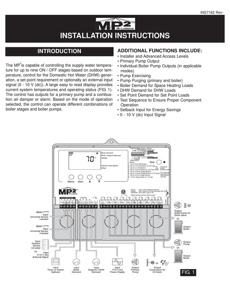
Lochinvar
Lochinvar INS7141 installation instructions
EnOcean
EnOcean Trio2Sys O2LINE 10020057 Series Installation and operating manual
Trane
Trane ZUSTATALS510 instruction manual

Toss
Toss RESISTRON ROPEX RES-409 operating instructions
