manuals.online logo
Brands
  1. Home
  2. •
  3. Brands
  4. •
  5. Calflex
  6. •
  7. Plumbing Product
  8. •
  9. Calflex Carimali DREAM User manual

Calflex Carimali DREAM User manual

This manual suits for next models

2

Other Calflex Plumbing Product manuals

Calflex Carimali 21820-CR User manual

Calflex

Calflex Carimali 21820-CR User manual

Calflex CARIMALI 21620-CR User manual

Calflex

Calflex CARIMALI 21620-CR User manual

Calflex CARIMALI DREAM 23000-CR User manual

Calflex

Calflex CARIMALI DREAM 23000-CR User manual

Calflex Carimali 0P001-CR User manual

Calflex

Calflex Carimali 0P001-CR User manual

Calflex CARIMALI 21610-CR User manual

Calflex

Calflex CARIMALI 21610-CR User manual

Calflex COSI User manual

Calflex

Calflex COSI User manual

Popular Plumbing Product manuals by other brands

Moen SANI-STREAM 8797 manual

Moen

Moen SANI-STREAM 8797 manual

Grohe Allure Brilliant 19 784 manual

Grohe

Grohe Allure Brilliant 19 784 manual

Cistermiser Easyflush EVO 1.5 manual

Cistermiser

Cistermiser Easyflush EVO 1.5 manual

Kohler Triton Rite-Temp K-T6910-2A installation guide

Kohler

Kohler Triton Rite-Temp K-T6910-2A installation guide

BEMIS FNOTAB100 Installation instruction

BEMIS

BEMIS FNOTAB100 Installation instruction

Hans Grohe ShowerTablet Select 700 13184000 Instructions for use/assembly instructions

Hans Grohe

Hans Grohe ShowerTablet Select 700 13184000 Instructions for use/assembly instructions

Akw Stone Wash Basin Installation instructions manual

Akw

Akw Stone Wash Basin Installation instructions manual

Enlighten Sauna Rustic-4 user manual

Enlighten Sauna

Enlighten Sauna Rustic-4 user manual

Moen ShowHouse S244 Series quick start guide

Moen

Moen ShowHouse S244 Series quick start guide

Sanela SLWN 08 Mounting instructions

Sanela

Sanela SLWN 08 Mounting instructions

Franke 7612982239618 operating instructions

Franke

Franke 7612982239618 operating instructions

Heritage Bathrooms Granley Deco PGDW02 Fitting Instructions & Contents List

Heritage Bathrooms

Heritage Bathrooms Granley Deco PGDW02 Fitting Instructions & Contents List

Tres TOUCH-TRES 1.61.445 instructions

Tres

Tres TOUCH-TRES 1.61.445 instructions

STIEBEL ELTRON WS-1 Operation and installation

STIEBEL ELTRON

STIEBEL ELTRON WS-1 Operation and installation

Miomare HG00383A manual

Miomare

Miomare HG00383A manual

BELLOSTA revivre 6521/CR1 quick start guide

BELLOSTA

BELLOSTA revivre 6521/CR1 quick start guide

American Standard Heritage Amarilis 7298.229 parts list

American Standard

American Standard Heritage Amarilis 7298.229 parts list

BorMann Elite BTW5024 quick start guide

BorMann

BorMann Elite BTW5024 quick start guide

manuals.online logo
manuals.online logoBrands
  • About & Mission
  • Contact us
  • Privacy Policy
  • Terms and Conditions

Copyright 2025 Manuals.Online. All Rights Reserved.

INSTALLAZIONE –INSTALLATION
MONTAGE –EINBAU
SOFFIONE "DREAM" INOX
INCASSO-SOFFITTO D340
"DREAM" INOX CEILING BUILT-IN
SHOWER HEAD D340
“DREAM” INOX CIEL DE PLUIE
ENCASTRE’ D340
“DREAM” INOX DUSCHKOPF IN
UNTERPUTZAUSFÜHRUNG D340
Art. 23069X-CR
2
AVVERTENZE:
L’impianto deve essere effettuato da personale autorizzato, certificato secondo le vigenti normative dello
stato in cui avviene l’installazione.
Tutto il materiale utilizzato deve essere conforme ai requisiti di sicurezza previsti per il tipo di applicazione,
secondo le vigenti normative dello stato in cui avviene l’installazione.
Tutti gli allacciamenti (idrico ed elettrico) devono essere perfettamente isolati gli uni dagli altri e fissati in
maniera stabile.
WARNINGS:
The plant must be made by an authorised staff and must be certified at the norms in use in the country
where the installation is made.
All the material used must be conformed to the safety equirements forecast for this type of installation, as
per the norms which are effective in the country where the installation is made.
All (hydraulic and electric) connections must be perfectly isolated one from the other and stably fixed.
AVERTISSEMENTS:
L'implant doit être effectué par un personnel autorisé, certifié selon les normes en vigueur du pays dans
lequel a lieu l'installation.
Tout le matériel utilisé doit être conforme aux requis de sécurité prévus pour ce type d'application, selon
les normes en vigueur du pays où a lieu l'installation.
Tous les branchements (hydrique et électrique) doivent être parfaitement isolés les uns des autres et fixés
de façon stable.
HINWEISE:
Die Anlage muss von dazu berechtigtem Personal installiert werden, zertifiziert entsprechend der
Rechtsvorschriften, welche in dem Land gelten, in dem die Installation vorgenommen werden soll.
Das gesamte, verwendete Material muss den Sicherheitsanforderungen entsprechen, welche für diese Art
der Anwendung vorgesehen sind, entsprechend der Rechtsvorschriften, welche in dem Land gelten, in dem
die Installation vorgenommen werden soll.
Alle Anschlüsse (Wasser- und Elektroanschlüsse) müssen perfekt voneinander isoliert sein und auf
beständige Art und Weise fixiert sein.
3
FUNZIONAMENTO CROMOTERAPIA:
1° pressione pulsante (circa 1s): avvio ciclo cromoterapia
2° pressione pulsante (circa 1s): arresto ciclo cromoterapia su colore desiderato
3° pressione pulsante (circa 1s): spegnimento led
CHROMOTHERAPY FUNCTIONING:
1° button pressing (about 1s): starting chromotherapy cycle
2° button pressing (about 1s): stop chromotherapy cycle on desired colour
3° button pressing (about 1s): led off
FONCTIONNEMENT CHROMOTHÉRAPIE:
1° Pression sur bouton (environ 1 seconde) = mise en fonction du cycle des couleurs de la chromo thérapie
2° Pression sur bouton (environ 1 seconde) = arrêt du cycle chromo thérapie sur couleur désirée
3° Pression sur bouton (environ 1 seconde) = led éteints
LAUF DER CHROMOTHERAPIE:
Erster Druck des Knopf (zirka 1“): Einleitung des Chromotherapie-Zyklus.
Zweiter Druck des Knopf (zirka 1“): Stillung des Chromotherapie-Zyklus unter wünsche Farbe.
Dritter Druck des Knopf (zirka 1“): Löschen der Led.
FUNZIONAMENTO LUCETERAPIA:
1° pressione pulsante (circa 1s): accensione led
2° pressione pulsante (circa 1s): spegnimento led
LIGHT-THERAPY FUNCTIONING:
1° button pressing (about 1s): led lighting
2° button pressing (about 1s): led off
FONCTIONNEMENT LUMIÈRE THÉRAPIE:
1° Pression sur bouton (environ 1 seconde) = allumage led
2° Pression sur bouton (environ 1 seconde) = led éteints
LAUF DER LICHTTHERAPIE:
Erster Druck des Knopf (zirka 1“): Einschalten der Led.
Vierter Druck des Knopf (zirka 1“): Löschen der Led.
4
Collegamento elettrico
Electrical connection
Branchement électrique
Elektroanschlüsse
230 V
3,5 V
3,5 V
5
Pre-installazione
Pre-installation
Pré-installation
Vormontage
SOFFIONE
/
SHOWER HEAD
CONTROSOFFITTATURA
/
FALSE CEILING
COLLEGAMENTO ELETTRICO 3,5V
(in dotazione)
/
ELECTRICAL CONNECTION 3,5V
(supplied)
COLLEGAMENTO ELETTRICO
230V 50Hz (EUR) o 120V 60HZ (USA)
(non in dotazione)
/
ELECTRICAL CONNECTION
230V 50Hz (EUR) o 120V 60HZ (USA)
(not supplied)
USCITA ACQUA
M1/2”G (EUR) o M1/2”NPT (USA)
/
WATER CONNECTION
M1/2”G (EUR) o M1/2”NPT (USA)
PULSANTIERA
(in dotazione)
/
SWITCH CONTROL
(supplied)
INTERRUTTORE ON/OFF
(non in dotazione)
/
SWITCH ON/OFF
(not supplied)
6
MURO GREZZO /
RAW WALL
INTONACO /
PLASTER
A FILO COL MURO GREZZO
/
AT THE SAME LEVEL OF RAW WALL
.4
.2
.1
.3
A.C.
230V
o
120V
70
36
76
53
93
Ø20
M1/2”G
o
M1/2”NPT
.5
7
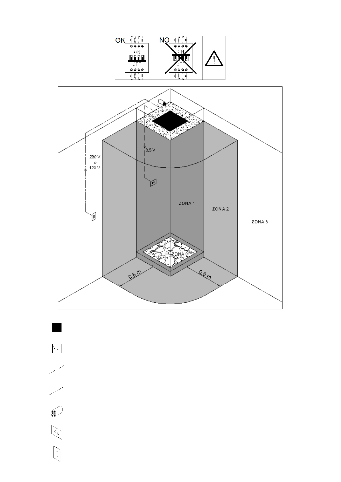
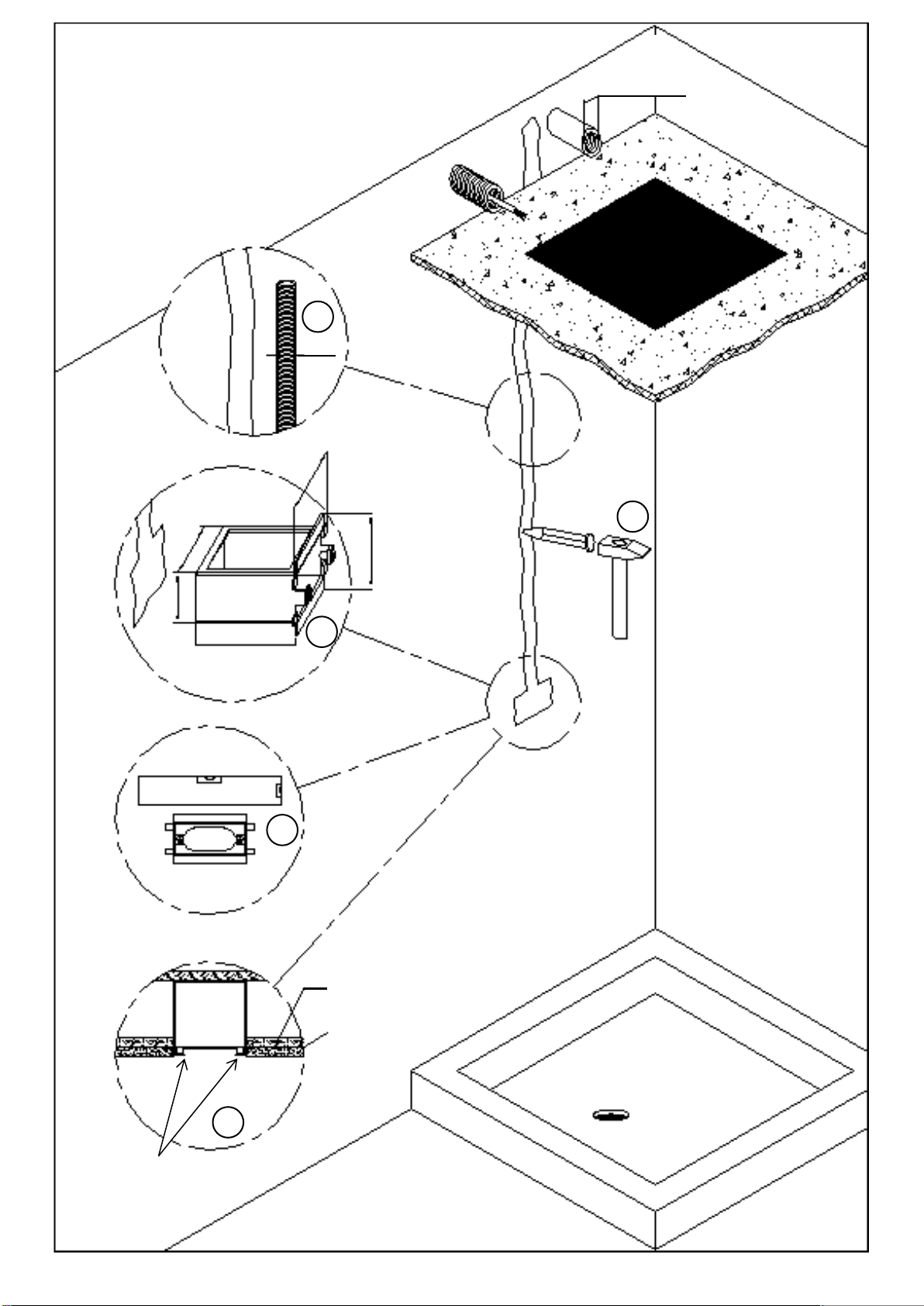
Predisporre un collegamento a soffitto con uscita M1/2“G (EUR) o M1/2“NPT (USA) in prossimità della futura sede del
soffione e un controsoffitto rinforzato avente uno spessore compreso tra 7 e 21 mm posto ad una distanza dal soffitto non
inferiore a 10 cm.
ATTENZIONE: Assicurarsi che il controsoffitto sia perfettamente in bolla.
Predisporre un interruttore generale all’interno della zona 3 o al di fuori di essa (no zona 0, 1, 2) e un collegamento elettrico
da 230V 50Hz (EUR) o 120V 60HZ (USA) al di sopra del cartongesso.
ATTENZIONE: Assicurarsi che non vi sia corrente in tutte le fasi d’installazione e/o manutenzione.
Predisporre tubazione (tubo corrugato Ø20) e vaschetta (in dotazione) per la pulsantiera interna dello spazio doccia.
ATTENZIONE: È inoltre necessario seguire scrupolosamente le istruzioni di montaggio al fine di installare il prodotto in
maniera corretta; a tale proposito il produttore non risponde nel caso di un utilizzo o d’installazioni errate.
Run the water pipe to the ceiling with M1/2“G (EUR) or M1/2“NPT (USA) outlet for the showerhead and prepare a reinforced
false ceiling from 7 to 21 mm thick that must be at a minimum distance of 10 cm from the ceiling.
WARNING: Make sure that the false ceiling is perfectly level.
Prepare a general switch inside the zone 3 or outside it (not in zones 0, 1 or 2) and a 230V 50Hz (EUR) or 120V 60HZ (USA)
electrical connection above the plasterboard.
WARNING: Make sure that the electricity is switch out during all the installation and maintenance phases.
Prepare the pipe (Ø20 corrugated pipe) and the supplied kit for the inside button switch of the shower space.
WARNING: It is also necessary to respect scrupulously the assembling instruction in order to install the product correctly; the
producer is not responsible in case of wrong use or incorrect installation.
Préparer la prise d’eau pour le ciel de pluie au plafond avec sortie M1/2“G (EUR) ou M1/2“NPT (USA) ainsi que un faux
plafond renforcé entre 7 et 21 mm d'épaisseur qui doit être placé à une distance minimum de 10 cm du plafond.
ATTENTION: S’assurer que le faux plafond soie parfaitement à niveau.
Prédisposer un interrupteur général à l'intérieur de la zone 3 ou en dehors de celle-ci (pas en zone 0 ni 1 ni 2) et préparer un
branchement électrique 230V 50Hz (EUR) ou 120V 60HZ (USA) au-dessus de la plaque de plâtre.
ATTENTION: S'assurer que le courant est coupé durant les phases de montage et durant celles de manutention.
Préparer la tuyauterie (tube ondulé de Ø20) et le kit fourni pour le bouton de démarrage dans l’espace de douche.
ATTENTION: Il est en outre nécessaire de respecter scrupuleusement les instructions de montage pour installer le produit de
façon correcte. Le producteur à ce propos décline toute responsabilité en cas d'emploi inapproprié et d'incorrecte installation.
Im Voraus eine Decke-Verbindung mit Ausgang M1/2“G (EUR) o M1/2“NPT (USA) in der Nähe des künftigen Standorts der
Duschkopf vorbereiten. Eine doppelte Zwischendecke mit einer Dicke zwischen 7 und 21 mm vorbereiten und sie mindestens
10 cm Entfernung aus der Decke positionieren.
VORSICHT: Stellen Sie sicher, dass die Zwischendecke perfekt nivelliert ist.
Innerhalb des Bereichs 3 (nicht in Bereich 0, 1, 2) oder außerhalb von diesem einen Schutzschalter vorbereiten und eine
elektrische Verbindung von 230 V 50 Hz (EUR) oder 120 V 60 Hz (USA) über dem Gips vorbereiten
VORSICHT: Dass während aller Installations- und/oder Wartungsphasen die Stromzufuhr unterbrochen ist.
Ein Rohr (Wellrohr Ø20) und Fach (im Lieferumfang enthalten) an der inneren Platte der Dusche Raum vorbereiten.
VORSICHT: Außerdem müssen unbedingt die Montageanweisungen befolgt werden, damit das Produkt auf korrekte Art und
Weise installiert werden kann; diesbezüglich haftet der Hersteller keinesfalls bei fehlerhafter Anwendung oder fehlerhafter
Installation.
8
Installazione
Installation
Montage
Einbau
Posizionare la dima in cartone (in dotazione) sul controsoffitto nel punto di installazione desiderato.
Position the cardboard template (supplied) on the false ceiling in the required installation point.
Positionner le gabarit en carton (fourni) sur le faux plafond de plâtre dans le point d'installation requis.
Den Schablone (immer eingebaut) auf der Zwischendecke in der gewünschten Installation-Stelle positionieren.
Tracciare la posizione dello scasso e dei fori di fissaggio.
Trace the position of the cavity and of the fastening holes.
Tracer la position de la cavité et des trous de fixation.
Die Position der Nische und der Befestigungslöcher anzeichnen.
9
Tagliare e forare con punta Ø10 il controsoffitto in funzione della traccia eseguita al punto precedente.
Cut and drill the false ceiling using a Ø10 drill bit according to the trace made under previous point.
Couper et percer le faux plafond avec une mèche Ø10 selon la trace réalisée au point précédent.
Den Gipskarton mit einer Ø10 Spitze schneiden und lochen, in Abhängigkeit von der Spur in den vorherigen Punkt
ausgeführt.
Inserire i tasselli.
Insert the plugs.
Insérer les fiches.
Die Dübel einstecken.
10
Mettere in bolla e fissare la piastra della pulsantiera all’interno dello spazio doccia serrando le 2 viti a testa bombata fornite
con chiave a brugola da 2,5 mm.
Put in the correct bubble position with a level and secure the plate of the inside button switch of the shower space by
screwing up the two supplied pan head screws with a 2.5 mm Allen wrench.
Mettre à niveau et fixer la plaque du bouton de démarrage dans l’espace de douche en serrant les deux vis à tête bombée
fournies avec l’aide d’une clé Allen de 2,5 mm.
Setzen Sie in Blase und befestigen Sie die Platte des Panels im Duschbereich. Ziehen Sie die 2 geliefert bombierter Kopf
Schrauben mit 2,5 mm Inbusschlüssel.
Siliconare il retro della piastra per evitare infiltrazioni d’acqua nella parete.
Siliconize the back of the plate to avoid water infiltrations in the wall.
Mettre du silicone sur la face arrière de la plaque pour éviter infiltrations d’eau dans la paroi.
Setzen Sie Silikon auf der Rückseite der Platte um Eindringen des Wassers zu meiden.