Calibre VANTAGE-HD2 User manual

30 April 2013 © Calibre UK Ltd
VANTAGE-HD
&
VANTAGE-HD2
User Manual
Issue 1.3.5a

Issue 1.3.5 14 December 2007 © Calibre UK Ltd Page i
Welcome to the Vantage-HD Manual
For technical support please see the Home Theater section of our website
http://www.calibreuk.com/home_theater.php.
If the web site does not provide the information you require, please contact your dealer, installer or
distributor in the first instance, or if they are unable to resolve your query please
VANTAGE MANUAL REVISION
Note this manual details the Vantage-HD functions and features assuming that you have installed issue 1.3.4
Firmware. Earlier versions of firmware may not include all the items described in this manual See section 1.8 for
details on updating the firmware.
COPYRIGHT & LIMITED WARRANTY
This document and the software described within it are copyrighted with all rights reserved. Under copyright laws,
neither the documentation nor the software may be copied, photocopied, reproduced, translated, or reduced to
electronic medium or machine readable form, in whole or in part, without prior written consent of Calibre UK Ltd
("Calibre"). Failure to comply with this condition may result in prosecution.
Calibre provides a limited warranty for Vantage-HD covering defects in manufacture and materials for a period of
12 months from date of purchase. This warranty covers parts and labor within this period but excludes shipping
charges and expressly excludes damage or defects caused by misuse, abuse, modification, alteration or failure
during firmware/software upgrading.
In the event of product failure, contact your dealer, installer or distributor for return/repair information. Unsolicited
product shipments to Calibre will not be processed for repair. DO NOT ship product directly to Calibre unless your
supplier has expressly instructed you to do so and has provided you with a returns authorisation number which
they have obtained from Calibre on your behalf for the purpose of this return.
Calibre does not warrant that this product will function properly in every hardware/software environment. Although
Calibre has tested the hardware, firmware and software within this product and reviewed the documentation,
CALIBRE MAKES NO WARRANTY OR REPRESENTATION, EITHER EXPRESS OR IMPLIED, WITH RESPECT
TO THIS HARDWARE OR SOFTWARE OR DOCUMENTATION, THEIR QUALITY, PERFORMANCE,
MERCHANTABILITY, OR FITNESS FOR A PARTICULAR PURPOSE. THE SOFTWARE CONTAINED WITHIN
VANTAGE-HD AND ALL DOCUMENTATION ARE LICENSED 'AS IS', AND YOU, THE LICENSEE, BY MAKING
USE THEREOF, ARE ASSUMING THE ENTIRE RISK AS TO THEIR QUALITY AND PERFORMANCE. IN NO
EVENT WILL CALIBRE BE LIABLE FOR DIRECT, INDIRECT, SPECIAL, INCIDENTAL, OR CONSEQUENTIAL
DAMAGES ARISING OUT OF THE USE OR INABILITY TO USE THE SOFTWARE OR DOCUMENTATION,
even if advised of the possibility of such damages. In particular, and without prejudice to the generality of the
foregoing, Calibre has no liability for any programs or data stored or used with Calibre software, including costs of
recovering such programs or data.
Calibre UK Ltd
Cornwall House, Cornwall Terrace
Bradford, West Yorkshire
BD8 7JS, England
Telephone +44 (0)1274 394125
Fax + 44 (0)1274 730960
Email vantage@calibreuk.com
Web-site www.calibreuk.com
Copyright (c) 2007 All World-wide Rights Reserved
All trade marks acknowledged
Calibre operates a policy of continued product improvement, therefore specifications are subject to change without
notice as products are updated or revised.
E&OE.

Issue 1.3.5 14 December 2007 © Calibre UK Ltd Page ii
CONTENTS
Contents ii
PRODUCT DESCRIPTION ................................................................................................................1
1.1. Product Overview.................................................................................................1
1.2. Packing List..........................................................................................................1
1.3. You Will Need......................................................................................................1
1.4. Physical Dimensions............................................................................................1
1.5. Controlling Your Vantage-HD...............................................................................1
1.6. Serial Control .......................................................................................................2
1.7. Infrared Control....................................................................................................2
1.8. Firmware Updates................................................................................................2
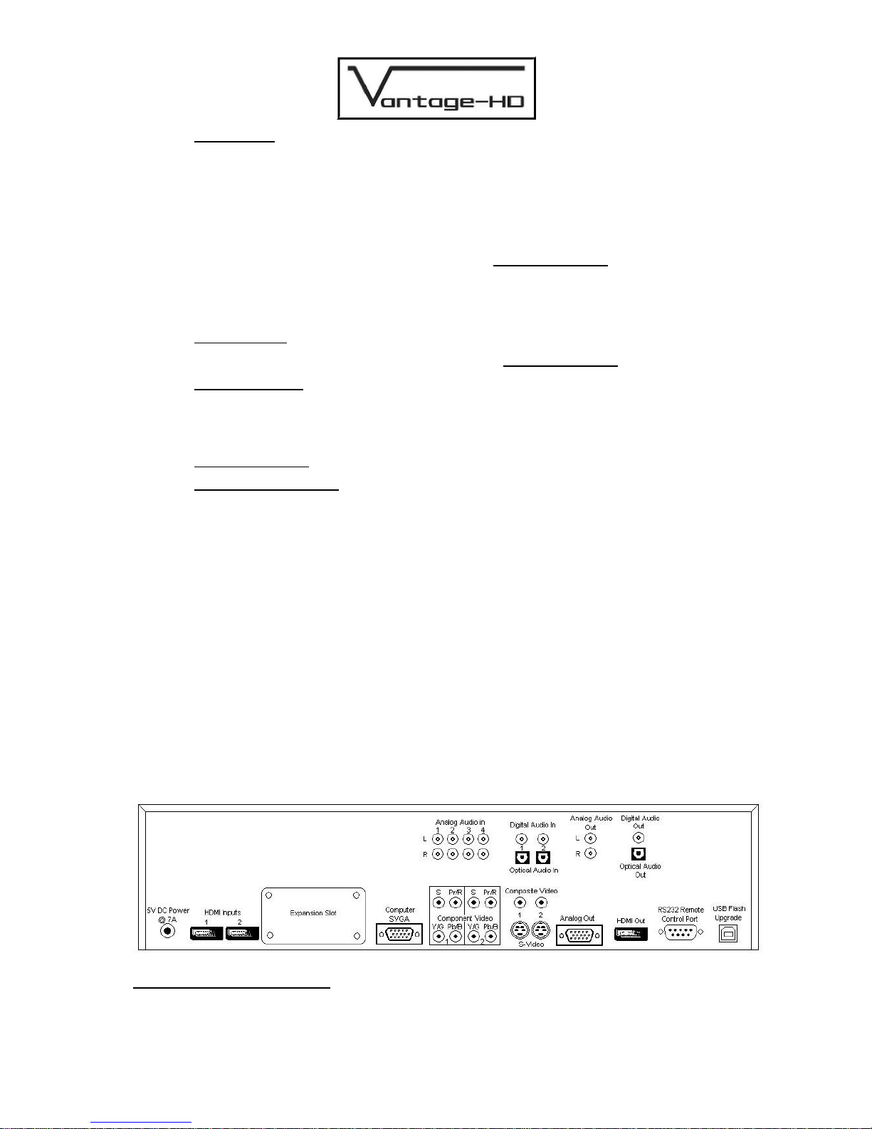
1.9. Rear Panel Connections......................................................................................2
1.10. Overheat Indication..............................................................................................3
1.11. HDCP Compliance Indication ..............................................................................3
1.12. Expansion Modules..............................................................................................3
CONNECTING VANTAGE-HD TO THE DISPLAY DEVICE..............................................................4
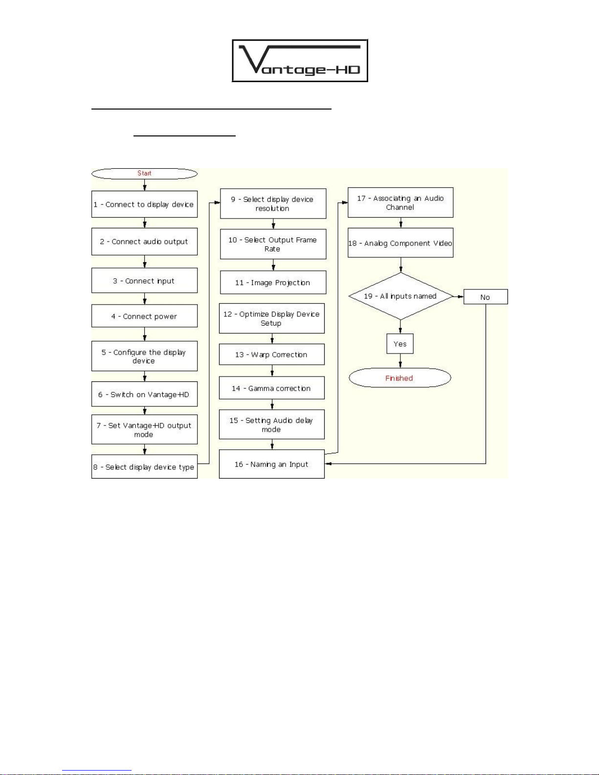
2.1. Correct Installation Order.....................................................................................4
CONNECTING VANTAGE-HD INPUTS.............................................................................................10
3.1. Introduction ..........................................................................................................10
3.2. Resetting An Input Channel................................................................................11
FREEING INPUT CHANNELS ...........................................................................................................12
4.1. Freeing a Video Channel.....................................................................................12
4.2. Freeing an Audio Channel...................................................................................12
SELECTING AN INPUT......................................................................................................................13
5.1. Via the OSD.........................................................................................................13
5.2. Via the Front Panel ..............................................................................................13
5.3. Via the Numeric Buttons on the Remote..............................................................13
ADJUSTING AN INPUT......................................................................................................................14
6.1. Introduction ..........................................................................................................14
PICTURE IN PICTURE.......................................................................................................................17
7.1. Introduction ..........................................................................................................17
INFORMATION MENU.......................................................................................................................19
8.1. Introduction ..........................................................................................................19
CONFIGURATION MENU..................................................................................................................20
9.1. Introduction ..........................................................................................................20
OUTPUT MODE DETAILS.................................................................................................................22
10.1. Introduction ..........................................................................................................22
10.2. Audio Output Formats..........................................................................................23
INPUT SIGNAL DETAILS...................................................................................................................24
11.1. Introduction ..........................................................................................................24
11.2. Video Inputs.........................................................................................................24
11.3. Component Video Input.......................................................................................24
11.4. SDI Input (optional)..............................................................................................24
11.5. HDMI / DVI Input..................................................................................................24
11.6. Computer (SVGA) Inputs.....................................................................................25
11.7. Audio Input Formats.............................................................................................25
POWER SUPPLY SPECIFICATION ..................................................................................................26
12.1. Introduction ..........................................................................................................26
REGULATORY APPROVALS ............................................................................................................27
13.1. CE and FCC Compliance.....................................................................................27
ENVIRONMENTAL AND SAFETY.....................................................................................................28
14.1. Operating .............................................................................................................28
14.2. Storage.................................................................................................................28
14.3. Safety Issues........................................................................................................28
HDMI CONNECTION ADVICE...........................................................................................................29
WARRANTY & SERVICE ADVICE.....................................................................................................32

Issue 1.3.5 14 December 2007 © Calibre UK Ltd Page 1 of 32
PRODUCT DESCRIPTION
1.1.
Product Overview
Vantage-HD is a state of the art digital image processor which provides market leading HD& SD per-
pixel multiple Iow-angle aperture-adjusted motion-adaptive de-interlacing and automatic film pull-
down correction for 3:2, 2:2 and non-standard and broken cadences, significantly outperforming the
capabilities of benchmark competitor products.
Vantage-HD2 includes additional processing features to allow output of 720p24, 1080p24 and 48p
signals from 24p inputs. Vantage-HD2 also includes a special passive cooling device for allow silent
operation.
Vantage-HD features studio-grade image processing algorithms for the very best scaling, film and
video noise reduction, MPEG artifact reduction and automatic audio time-line correction to maintain
lip-sync. Vantage-HD is a very flexible video and audio router with multiple HDMI and analog input
channels, digital, analog and optical audio support and optional HD-SDI compatibility.
Vantage-HD has special algorithms for plasma image enhancements, significantly reducing plasma
noise and improving grayscale reproduction. Image quality on large-screen LCDs are also much
improved by Vantage-HD. For projectors, Vantage-HD features the sharpest most flexible keystone
correction on the market and there is also an image warping option available for complex geometric
correction.
1.2.
Packing List
The following items are included with your Vantage-HD, if any items are missing please contact your
distributor.1. Vantage-HD
2. Power supply
3. Power cord
4. CD containing this manual
5. Remote control + batteries
6. Warranty card
1.3.
You Will Need
The following items will be required but are not supplied with your Vantage-HD
1. A suitable display device - see section 10.1 for details of the output modes supported by
Vantage-HD
2. Cable to connect to your display device
3. A signal source - see section 11 for details of the supported inputs
4. Cable to connect to your signal source
5. Audio processor and cable (required if not using HDMI to connect to the display device).
1.4.
Physical Dimensions
The Vantage-HD is approximately 16.4" (416mm) by 10" (253mm) by 3.4" (85mm) WxDxH
NOTE dimensions are excluding optional rack mounting kit.
An optional 19" by 2U rack mounting kit is available. Each bracket is attached by 2x 10-32 1/2" long
pan head screws.
1.5.
Controlling Your Vantage-HD
Setting up and controlling your Vantage-HD is achieved by a simple to use On Screen Display (OSD),
moving around the OSD can be achieved by using the navi-keys on the front of the Vantage-HD or by
using the remote control
Batteries are not installed when the unit ships to maximise their life.
PLEASE ENSURE THAT THE BATTERIES ARE INSERTED IN THE WAY SHOWN WITHIN THE
BATTERY COMPARTMENT OF THE REMOTE CONTROL.
WHEN BATTERIES BECOME DISCHARGED PLEASE REMOVE THEM IMMEDIATELY AND
DISPOSE OF THEM IN ACCORDANCE WITH THE INSTRUCTIONS SUPPLIED BY THE BATTERY
MANUFACTURER.
IF THE REMOTE CONTROL IS TO BE LEFT UNUSED FOR AN EXTENDED PERIOD OF TIME
PLEASE REMOVE THE BATTERIES TO PREVENT POSSIBLE DAMAGE CAUSED BY LEAKING.

Issue 1.3.5 14 December 2007 © Calibre UK Ltd Page 2 of 32
1.6.
Serial Control
Vantage-HD has a serial port which allows for the unit to be controlled via an integrated
home control system. The connector on Vantage-HD is a 9 way D-Type (female).
Pin 2 = Tx Pin 3 = Rx Pin 5 = Ground
The type of cable required will depend on your home control system but typically a 9 way
Male to 9 way Female connected straight through will allow serial control.
The serial control codes can be downloaded from www.calibreuk.com, please also note that
serial control may require the application of a firmware upgrade to your unit, via its USB port.
NOTE : Whilst in standby mode the only serial command that the Vantage-HD will respond
to is “Power On”.
1.7.
Infrared Control
The infrared control codes can be downloaded from www.calibreuk.com
1.8.
Firmware Updates
Calibre operates a policy of continued product improvement. As a result we may periodically
issue firmware updates; these are downloaded to Vantage-HD via the USB port.
Full details of the updates and how to download them are available on our website
www.calibreuk.com
1.9.
Rear Panel Connections
The following inputs are located on the rear panel of the Vantage-HD
1. Composite video via RCA jack (2x)
2. S-Video via 4 way mini DIN socket (2x)
3. Component video with or without separate sync via 3/4 RCA jack (2 sets)
4. HDMI version 1.1 (2x)
5. Expansion slot for input expander cards - takes HDMI card or HD-SDI card
6. Computer (SVGA) via 15 way HDD
7. Analog audio stereo pairs via RCA jack (4 sets)
8. S/PDIF coaxial audio (2x)
9. S/PDIF optical audio (2x)
10. Power jack
The following outputs are located on the rear panel of Vantage-HD
1. Analog video output via 15 way HDD (1x)
2. HDMI version 1.1 (1x)
3. Analog audio stereo pair via RCA jack (1 set)
4. S/PDIF coaxial audio (1x)
5. S/PDIF optical audio (1x)
Figure 1 below details the connections to Vantage-HD.
Figure 1 Rear Panel Connections

Issue 1.3.5 14 December 2007 © Calibre UK Ltd Page 3 of 32
1.10.
Overheat Indication
Should the video processor within the Vantage-HD get too hot it will automatically go into
standby mode and the two front panel LEDs will flash red.
Should this happen we recommend that you clean the fan if it is clogged with dust, if it is not
clogged then we recommend that you change the fan. If your model is a fanless Vantage-
HD2 the overheat indication is very unlikely unless you have installed it with a very hot
device underneath and/or with the cooling vents obstructed.
When the processor has cooled sufficiently pressing the standby button will bring the unit
out of standby.
1.11.
HDCP Compliance Indication
FULL HDCP COMPLIANCE: The Connection/HDCP status LED (Left-most LED) and
displayed image now indicate the following conditions:
OFF: No valid input signal detected;
GREEN: Non-HDCP protected input signal detected - Non-HDCP protected
input signals can be viewed at any output resolution on any display;
AMBER IMAGE:HDCP protected input signal detected - Limited Output
mode - If a selected input signal is HDCP protected and the connected display is
not HDCP certified then the protected signal can only be viewed when the output
resolution selection is no greater than 480 lines. Anything above will result in a
HDCP protected blank indicated by an Amber/Yellow screen and RED status LED;
RED: HDCP protected input signal detected - HDCP certified Display found -
If a selected input signal is HDCP protected and the display is HDCP compatible,
there will be no limits on the choice of output resolution.
1.12.
Expansion Modules
Three expansion module are available for your Vantage-HD, these are
1) Dual 1.3 HDMI input
2) Dual HD SDI input
3) Single HD SDI input
Installation instructions for the expansion modules are supplied with the module. The
firmware will automatically detect the modules and they can the be named and configured
as per standard Vantage-HD inputs.
Please contact you Vantage-HD retailer for more information regarding expansion modules.

Issue 1.3.5 14 December 2007 © Calibre UK Ltd Page 4 of 32
CONNECTING VANTAGE-HD TO THE DISPLAY DEVICE
2.1.
Correct Installation Order
The flow chart below details the correct order in which to install your Vantage-HD; following
this order will assist with trouble free installation.

Issue 1.3.5 14 December 2007 © Calibre UK Ltd Page 5 of 32
1.
Connect to
display device
Connect Vantage-HD SVGA (RGBHV) output or HDMI output to your
display device. If connecting a DVI display device you need to use an
HDMI to DVI converter which we recommend you locate at the display
end of the cable.
2.
Connect audio
output
Connect Vantage-HD audio Coaxial, Optical or Analog output to audio
processor, if HDMI audio output is not being used.
Note: For best audio performance it is recommended that Coaxial or
Optical audio be used, not HDMI audio. Some HDMI sources do not
correctly comply with HDMI specifications which can cause audio
distortion or loss of audio. If this is experienced, please change to using
Coaxial or Optical audio, or consult the supplier of that HDMI source
device.
3.
Connect input
Connect input video and audio signals to Vantage-HD.
4.
Connect Power
Connect power supply provided with Vantage-HD to Vantage-HD power
inlet jack.
THIS POWER SUPPLY CARRIES A LABEL SHOWING THAT ITS DC
OUTPUT IS 5V at 7A or 8A DEPENDING ON THE VARIANT
SUPPLIED. DO NOT CONNECT ANY OTHER POWER SUPPLY TO
VANTAGE-HD. USE OF ANY OTHER POWER SUPPLY WILL
INVALIDATE YOUR PRODUCT WARRANTY
Connect the Vantage-HD PSU to your mains outlet and turn on the mains
outlet if it is switched
5.
Configure the
display device
Turn on your display device and select the input channel to which you
have connected Vantage-HD
6.
Switch on
Vantage-HD
Turn on Vantage-HD by pressing the Power (bottom right) button on the
front panel, or by pressing the On button on the remote control.
7.
Set Vantage-HD
output mode
A new Vantage-HD unit will power up in 640x480 @ 60Hz output mode
since this should be compatible with all common display devices. If your
Vantage-HD has previously been connected it may power up in a
different mode. If this mode is not compatible with your display you can
easily revert to the 640x480 @ 60Hz output mode by simultaneously
pressing the front panel Input key and OK key (OK is the center key of
the 5-button navi-key).
8.
Select display
device type
Press the Menu key to bring up the OSD menu. Scroll to the Output
Settings menu using the top/bottom navi-keys. Go into that menu by
pressing the right navi-key.
First choose your type of display by using the up/down navi-keys to scroll
to the Display menu item (if not already highlighted) and pressing OK (the
center button of the navi-key). The options which appear are:
a) LCD - for direct-view LCD displays
b) Plasma - for plasma displays
c) Projector - for solid-state (digital) projectors such as DLP,
LCD, LCOS, DILA or any other type of digital or analog
projector
Choosing the appropriate type of display is important since menu items
such as temporal noise reduction and how the OSD is generated are pre-
set to different default values depending on the display type and different
menu items appear or are hidden such as keystone correction.

Issue 1.3.5 14 December 2007 © Calibre UK Ltd Page 6 of 32
Picture 1 Select Display Device Type
9
Select display
device
resolution
Choose the correct display resolution by scrolling down to the Resolution menu
item and pressing OK to display the list of available modes. Note the scroll bar at
the left of the list - it is too long to display the full list on screen so you must
scroll up and down it to see all modes.
For best performance it is critical that you select a mode which is equal to the
native resolution of the display device you are using, provided that the display
supports its native mode. This is to ensure that the internal scaling within your
display device is not operating.
Depending on the mode you choose, Vantage-HD may have to re-boot to
change resolution. If this occurs you need to re-enter the Output menu by
pressing Menu, scrolling to Output Menu with the up/down keys and entering the
Output Menu with the right key.
Note: it is possible to program custom output modes. This requires detailed
information on the native mode(s) of your display device. Incorrect programming
of custom modes can cause damage to some types of display device, do not
attempt to program a custom output mode unless you are sure you have the
correct information and are confident that you have the necessary video signal
knowledge to do this.
A customizable sync polarity for the current output mode can be selected via the
Output Menu. This allows your Vantage-HD to work with some older plasma
panels.
If you inadvertently select a frame rate which is incompatible with your display,
press and hold the “Menu” and “Enter” (center of navi-key) front panel buttons
simultaneously for approximately 3-5 seconds to restore the output mode to

Issue 1.3.5 14 December 2007 © Calibre UK Ltd Page 7 of 32
Picture 2 Select Display Device Resolution
10
Select Output
Frame Rate
Select the Frame Rate option on the menu. This determines whether the output of
Vantage-HD remains at a constant 59.94Hz, constant 50Hz, or automatically switches
between the two depending on the type of incoming signal being displayed.
Auto mode gives best motion performance in a viewing scenario where you are looking at
content which may be 59.94Hz or 50Hz (North America and anywhere using the NTSC
system usually runs at 59.94Hz, Europe and anywhere using PAL or SECAM usually runs
at 50Hz; there are exceptions though in both cases.) However when Auto mode is
selected there may be display glitches or display re-sync delays when switching between
inputs or when the input signal is lost - this is due to output frame rate changes affecting
the operation of your display device. Additionally, some HDMI display devices will not
operate correctly in Auto mode due to limitations inherent within those displays.
If you are only using 59.94Hz sources, or only using 50Hz sources, it is strongly
recommended you select fixed 59.94Hz or 50Hz respectively so as to improve the input
switching characteristics.
Selecting 50Hz output mode with 59.94Hz input material, or vice versa, causes frame rate
conversion to occur. This can cause slight degradation in motion performance so is not
recommended, but can be used for display devices which are not compatible with the
incoming field rate.
Note1: 60Hz display devices should correctly display 59.94Hz modes.
Note2: Some HDMI sources may potentially lose HDCP authentication if the output frame
rate is different from the input frame rate.
Vantage-HD2 models include an additional menu item to allow 24p or 48p output
when an incoming 24p signal is detected. 48p is always available for selection. 24p
is only available when the output mode is 720p or 1080. Be sure to check carefully
that your display device can support 24p or 48p natively, otherwise severe image
degradation or total loss of image may occur.
If you inadvertently select a frame rate which is incompatible with your display, press and
hold the “Menu” and “Enter” (center of navi-key) front panel buttons simultaneously for

Issue 1.3.5 14 December 2007 © Calibre UK Ltd Page 8 of 32
11
Image
Projection
Image Projection - allows correction for the orientation and location of the
projector relative to the screen. Press OK to show list then scroll up/down list
with up/navi-keys, press OK to choose the correct mode. Options are:
a) Front Table - projector is in front of screen and correct way up
b) Front Ceiling - projector is in front of screen but upside down
c) Rear Table - projector is behind screen but right way up
d) Rear Ceiling - projector is behind screen and upside down
12
Optimize Display
Device Setup
When connecting your display via the SVGA (RGBHV) connector it is imperative
that the pixel clock and phase settings are correctly adjusted on the menu
system of your display device. For information on how to access these features
see the user manual supplied with your display device. Note: You must set
Vantage-HD to the native resolution of your display device BEFORE adjusting
the pixel clock and phase settings on your display.
To set the pixel clock, with no input displayed on Vantage-HD but with the OSD
present and the blue background shown, adjust the pixel clock setting (on your
display device, not on Vantage-HD) to remove all vertical noise bands from the
blue background. Correct adjustment will cause the vertical bands to move
further apart and reduce in number until they eventually disappear. Many good
displays will automatically select the correct pixel clock setting, but some will not.
IMPORTANT: See Chapter 10 - Output Mode Details for detailed information on
output mode timings including information on the correct pixel clock setting - the
total number of pixel clocks per line. See also Note (b) below when using
1366x768/1360x768 modes.
To set the pixel phase, first set the pixel clock correctly (see above) and
then adjust the pixel phase to remove all horizontal jitter and noise from
the background and the OSD, in particular you should adjust for best
sharpness of the OSD text and graphics.
PIXEL CLOCK AND PHASE ADJUSTMENTS WITHIN THE DISPLAY
DEVICE ARE NOT APPLICABLE WHEN USING A DVI OR HDMI DISPLAY
DEVICE.
Notes:
a) Some 1024x1024 plasmas do not correctly support 1024x1024 native
resolution, in this case you must unfortunately select 1024x768 or 1280x768,
experiment to see which gives best performance.
b) There are two 1366x768 modes and a 1360x768 mode provided. This is
because some types of plasma and LCD with this resolution need
different signal timings compared with those which are considered
standard for this format. As a general rule, 1366x768 modes will give
better performance than 1360x768 but some displays do not support
1366x768 modes. The key difference between the two 1366x768 modes
is the length of line blanking. Pick the 1366x768 mode which allows you
to correctly set the pixel clock on your display device and which does not
cause bad clamping. (If the picture appears very dark or very bright then
it is incorrectly clamped due to the selected mode not being compatible
with your display - try the other 1366x768 mode or the 1360x768 mode
instead).
c) There is also a 1368x768GTF mode supported. This is the CEA-
recognised implementation of 1366x768 - it actually provides an active image
size of 1366, not 1368. This is the recommended mode for use with modern
HDMI/DVI compliant 1366x768 displays.
d) 852x480 mode may need to be used for plasma screens with resolutions
of 852 or 853 pixels. Many 853 pixel plasma displays do not actually
support incoming modes with an odd number of input pixels.

Issue 1.3.5 14 December 2007 © Calibre UK Ltd Page 9 of 32
e) Never pick a mode with more display lines than the native format of your
display device, selecting a higher resolution mode will not increase the
system performance, it will instead degrade the picture significantly since
it will cause the internal scaler within your display to downsize the picture
resulting in loss of detail and artifacts.
Depending on the frame rate mode you choose, Vantage-HD may have to re-
boot to change resolution. If this occurs you need to re-enter the Output menu
by pressing Menu, scrolling to Output Menu with the up/down keys and entering
the Output Menu with the right key.
13
Warp Correction
& Image
Positioning
Warp Correction - only applicable if the chosen display type is Projector.
This allows for correction of vertical and horizontal keystone errors caused by
misalignment of the projector to the screen. Correction up to +/- 30 degrees
vertically and +/-40 degrees horizontally are possible, within the constraints of
the chosen native resolution which is dependent on the display device - a higher
resolution display device will give better results at more extreme angles of
adjustment.
Select the Warp Correction menu item using the OK key, then choose which
corner to manipulate, then use the up/down and left/right navi-keys to
manipulate the image by changing the angle of adjustment in the vertical and
horizontal planes respectively. The X and Y coordinates of the corner being
moved is displayed.
Note: Although Vantage-HD's Warp Correction allows for extreme off-angle
picture geometry correction and maintains display resolution to the very best
possible level even in such situations, Vantage-HD cannot correct for mis-
focussing of the projector lens. Depending on the physical and optical
characteristics of the optics within your projector, focus errors may occur at
extreme projection angles which may cause one side of the image to appear
less sharp than the other. After setting warp on Vantage-HD you should adjust
the focus of your projector lens to obtain best overall picture sharpness, paying
particular attention to sharpness in the center of your screen for viewing movies
and TV.
Image positioning - this allows fine-tuning of the output image position on the
chosen display device. Use this function to move the output image left/right or
up./down and to alter the size of the image. Note that this function specifically
controls the output image position, not the input image capture area.
Custom Mode allows the output timing to be defined, once this has been done
the Custom Mode can be selected from the Output Resolution list.
14
Gamma
Correction
Scroll to Output Gamma Mode and choose the gamma mode you require. This
should be left set to Linear unless you also choose the correct input gamma for
every input signal you connect. It is used to map an incoming gamma curve to a
different outgoing gamma curve.
It is possible to set up a custom gamma response to suit your display device.
15
Setting Audio
Delay Mode
Audio Delay - the audio delay through Vantage-HD is automatically set to
compensate for the delay through Vantage-HD which is typically 5-7 fields. The
Audio Delay option on the Output Menu does not override this automatic setting
but allows fine calibration of the audio delay in steps of approximately 1 mS, to
advance or retard the audio so as to compensate for further delays in your
display device or your audio system. If you notice lipsync errors when viewing
program material, you can use this option to reduce or remove that error. Fine
tuning of the audio delay can only be set correctly when viewing real program
material so should not be adjusted at this stage.
Output configuration is now complete, apart from fine-tuning the audio delay, which may
require adjustment later, depending on your display device and audio system. Exit the
Output Menu by pressing the left navi-key.

Issue 1.3.5 14 December 2007 © Calibre UK Ltd Page 10 of 32
CONNECTING VANTAGE-HD INPUTS
3.1.
Introduction
It is now necessary to define which input channels are connected and to pair the correct
audio channel with each video channel. To begin to do this, scroll down to the Input
Connections menu and enter that menu by pressing the right navi-key.
By default, no video channels and no audio channels are active. You must define which
channels are connected on the Input Connections menu and choose whether or not each
video channel has an associated audio channel. Only those video channels which are
physically present on your Vantage-HD are shown, those which are grayed-out require an
additional expansion module.
NOTE If your input device allows you to select an output resolution please select the native
resolution of the image to be displayed.
16.
Naming an
Input
To enable or disable a video channel, scroll to that channel type with the up/ down
navi-keys, then press OK. You must then give that channel a name which means
something to you or your installation/system for future reference. Do this by using
the up/down navi-keys to scroll through the available characters and numbers (fast-
scroll through the list automatically activates after approx 2 seconds). Then use the
left/right navi-keys to move to the next character in the name, or go back to alter a
character you have already chosen. (Note: To delete a character and not replace it
with another, scroll with the up/down navi-keys to select the blank/space character.)
It is not possible to enable a video channel or associate a sound channel with it until
you have named that channel. Press the OK button when you have finished naming
that input, the channel will now automatically be enabled as an available input.
Input Number
(optional
configuration)
To enable direct-selection of an input channel, using the numeric keys on the remote
control, scroll to the Input Number with the up/down navi-keys, then press OK.
Select the desired number from the list the press OK.
Numeric selection is not essential for the operation of Vantage-HD but does provide
a quick method of getting to the desired input.
17. Associating an
Audio Channel
After naming the input channel, scroll down to the Sound Source menu item to
choose the associated sound channel and press OK to view the list of available
sound channels. If there is no associated sound channel (e.g. for a PC input with no
audio) choose None. Only those sound channels which have not already been
allocated to another video input channel are available for selection; those which
have already been allocated are grayed-out.
Note the scroll bar at the left of the list - there are too many audio channels to
display all at once, you must scroll up and down the list to see all the available
channel options.
Note: HDMI audio inputs can only be associated with the matching HDMI video
input. For best audio performance we recommend using Coax or Optical SPDIF
audio where supported by the source.

Issue 1.3.5 14 December 2007 © Calibre UK Ltd Page 11 of 32
18. For Analog
Component Video
Only
For analog Component Video inputs only, you can also choose whether the input
source provides YPbPr, YPbPrS, RGB or RGBS video.
It is important to select the correct color and sync format, otherwise the picture
coloration will be wrong or no picture may be displayed. Most North American DVD
players and set-top boxes output YPbPr. Most European (SCART) devices output
RGBS
It is also possible to choose between 0.7v and 1.0v video levels on the component
inputs. Most sources provide 0.7v video, plus 0.3v sync, but some do provide 1.0v
(excluding syncs). This can overload the input ADCs in Vantage-HD causing very
noticeable picture quality degradation in bright picture areas due to peak-level
compression.
If the 0.7v setting causes compression, change to 1.0v.
Note that incorrectly selecting 1.0v when the source is providing 0.7v will lead to a
very dark image.
Definition of that video input channel is now complete.
You should now repeat steps 16 to 18 to the define all the remaining video and audio
channels you wish to use. When you have finished defining input channels, exit the Input
Connections menu using the left navi-key to move back to the main menu on the left of the
OSD
3.2.
Resetting An Input Channel
Reset Channel
This very useful function resets all the input parameters to the default
settings for that input channel with the current selected display device
type. This enables you to recover to known settings.
Input Setup Menu

Issue 1.3.5 14 December 2007 © Calibre UK Ltd Page 12 of 32
FREEING INPUT CHANNELS
4.1.
Freeing a Video Channel
Should you wish to disable a video input, you may do so by re-selecting that video channel
from the Input Connections menu, selecting the Disable Channel function and then selecting
Yes from the warning message which appears. Disabling a video input channel not only
removes it from the input selections list, it also erases its name and de-allocates its
associated audio channel.
Note: If all possible input channels are disabled, the OSD will exit at the point at which the
last channel is disabled. This is because there are now no valid inputs so Vantage-HD has
switched to its unconfigured (default) mode of operation. In this default mode the input
channel to be displayed is undefined so may vary randomly. To start re-defining the input
channels, press the Menu button again and use the navi-keys to re-enter the Input
Connections menu.
4.2.
Freeing an Audio Channel
Should you need to free up a previously allocated channel, go to that video input channel
and select a different audio channel or no audio channel for association with that video input
channel.
Press OK when you have chosen the correct audio channel.
Note: HDMI inputs by default associate themselves with the HDMI audio on that HDMI video
channel. You can change this to any available digital or analog audio input if you wish, but
cannot cross-select audio from a different HDMI video channel, e.g. HDMI2 can use audio
from HDMI2 or from any analog or digital audio input, but HDMI2 video cannot be
associated with audio from HDMI1 input. Calibre recommends use of Coaxial or Optical
digital audio where the source device allows.

Issue 1.3.5 14 December 2007 © Calibre UK Ltd Page 13 of 32
SELECTING AN INPUT
5.1.
Via the OSD
Now you can choose from the input channels you have defined by scrolling up to the Input
Selection menu. Here you will find listed those input channels you have defined. Press the
right navi-key to enter the Input Selection menu, then scroll to the input you wish to view or
whose configuration you wish to alter. Press OK to select it.
5.2.
Via the Front Panel
Alternatively you can step through the defined input channels when the OSD is not displayed
by using the Input key on the front panel of Vantage-HD.
5.3.
Via the Numeric Buttons on the Remote
You can also direct-select an input channel by its number in the Input Selection listing, using
the numeric keys on the remote control.
It is also possible to change the allocated numbers for those input channels in the Input
Selection list. To do this scroll to that channel type with the up/down navi-keys, then press
OK. Scroll to the Input Number, then press OK. Select an alternative number from the list.
Note the order of the list does not change on the OSD.
Input Selection Menu

Issue 1.3.5 14 December 2007 © Calibre UK Ltd Page 14 of 32
ADJUSTING AN INPUT
6.1.
Introduction
When an input channel has been selected, an input type dependent Picture Controls menu
can be accessed. Note that for this menu to be fully accessible, a valid video input signal
MUST be connected to the chosen video input channel. All settings on the Picture Controls
menu are stored separately for each input channel and so do not affect the other inputs.
Note: Default settings for many items are dependent on the type of input channel and the
type of display device chosen.
To adjust the picture settings, scroll to the Picture Controls menu then press the right navi.
key to enter that menu.
MANY SETTINGS ARE SIGNAL-TYPE DEPENDENT. NOT ALL ADJUSTMENTS ARE
PRESENT FOR EVERY INPUT SIGNAL TYPE, THE LIST BELOW SHOWS ALL
POSSIBLE OPTIONS BUT THESE ARE NEVER ALL AVAILABLE SIMULTANEOUSLY
SINCE SOME ARE EXCLUSIVE TO ONE INPUT TYPE, SOME ARE EXCLUSIVE TO
ANOTHER INPUT TYPE. BE SURE TO HAVE THE CORRECT INPUT SOURCE
CONNECTED AND RUNNING, OTHERWISE THE CONTROLS MAY NOT HAVE THE
DESIRED EFFECT WHEN THE ACTUAL SIGNAL IS CONNECTED.
Brightness
Control of background level
Contrast
Control of video gain
Enhancement
Sharpness - Control of the sharpening enhancement filters' levels.
These are peaking filters to improve high-frequency response. Note that
setting this control too high on a signal which already has good high
frequency response will cause ringing or ghosting.
Detail Enhance - This is a very powerful function which performs a per-
pixel unsharp mask on the image content. It can be used to greatly
improve detail definition and clarity without causing image ringing or
ghosting. It improves both horizontal and vertical detail. Correct setting
of the detail enhance filter can make SD signals look nearly as good as
true HD.
Note: The enhancement settings apply to video input signals only, not
computer graphics signals.
Color
Saturation and Hue controls on a sub menu (video input signals only)
Pixel Clock & Phase
A submenu allowing adjustment of the pixel clock (total number of pixel
clocks per line) and the pixel phase for the SVGA (RGBHV) input only.
This menu item only appears with the SVGA input selected.
Auto Setup
Automatically adjusts the pixel clock and phase settings for the SVGA
input. This menu item only appears with the SVGA input selected.
Picture Format
Select from Normal, full Screen, Crop, Anamorphic or Flex Wide. A 2.35
Mode is available if Projector Mode is selected.
Aspect Ratio Adjust
A user-definable custom aspect ratio function is also available

Issue 1.3.5 14 December 2007 © Calibre UK Ltd Page 15 of 32
Picture Controls Menu
Video Filters
A submenu containing selection options for many image enhancement filters
including
(Video input
signals only)
CCS Cross Chrominance Suppression filter (reduction of chroma-crawl)
CUE Chroma Upsampling Error correction filter
ICP Interlace Chroma Problem filter - Reduces chroma interlace errors on
diagonals and curves
TNR Temporal Noise Reduction (removes "electronic" noise found on broadcasts,
film material and particularly noticeable on plasma screens; set to High to
significantly improve signal to noise ratio on plasmas)
MPEG
Selects whether MPEG spider and block noise is on or off and adjusts the
level of MPEG noise reduction for SD signals. Not applicable to HD formats –
use TNR for removal of all types of noise from HD formats.
Video Filters Menu

Issue 1.3.5 14 December 2007 © Calibre UK Ltd Page 16 of 32
Picture Settings
A submenu of picture control functions including
Contrast Enhance
Preconfigured contrast enhancements which can be selected to suit
your personal requirements and the material being viewed.
Color temperature
To select the color temperature of the incoming material. Options are
Warm, Neutral, Cold. With a 7200K display device (a typical
projector or LCD set to neutral) these correspond to nominal settings
of 6500K, 7200K & 9300K respectively. For neutral color temperature
response, that is, to leave the response of the program material
unmodified, select Neutral, this is the default setting.
There is also a user-defined color temperature setting whereby
individual R,G,B levels can be set so as to accurate calibrate a
particular input/source to the display device.
Input gamma mode
Used to re-map an input gamma to a different output gamma setting.
Only use this function if the output gamma has also been chosen on
the Output Settings menu, otherwise leave set to Linear
Black Level
Use to select or de-select 7.5IRE black level set-up adjustment.
Should always be on for HDMI video inputs and should usually be off
for analog video inputs.
Input Capture
Select the amount of overscan.
Input Window Shift
Allows horizontal and vertical adjustment (pan and tilt) of the
captured active image area within the overall display resolution.
Note: The range of position adjustment available is limited by the
characteristics of the signal timings from the image source
equipment: in some circumstances adjustment may not be possible,
particularly with HDMI/DVI signals.
Changes in output image position (to correct for projector alignment
errors or image positioning errors on the display device) should be
effected via the Warp corner-adjustment menu or the image position
controls on the output menu..
Picture Settings Menu

Issue 1.3.5 14 December 2007 © Calibre UK Ltd Page 17 of 32
PICTURE IN PICTURE
7.1.
Introduction
To enable PIP mode, scroll down the main menu to the Picture-in-Picture Settings menu
and press the right navi-key to enter that menu. To enable PIP, scroll to the PIP Enable
option and press the OK key. Note: You cannot use the PIP menu successfully without at
least two active inputs connected to Vantage-HD.
Selecting the input
Use the PIP Inputs menu to select which picture is displayed in the PIP
window
Swapping PIP
Use the PIP Swap function to swap the primary image with the PIP
image
Positioning the PIP
Use the PIP Position functions select the position and size of the PIP.
OSD not visible
When the PIP is displayed and the OSD menu is not on screen the navi-
key arrows can be used to move the PIP around the screen and re-size
the PIP window
Limitations
PIP Limitations - due to the high demands on the processing power
available within the Realta HQV chip when an HD main image is
displayed, full Video Processing is not always available when PIP is in
use.
If the main image is 1080i or 1080p and the PIP image is 720p, 1080i or
1080p the maximum available image processing bandwidth may be
exceeded. In such circumstances Video Processing is automatically
disabled resulting in reduced image quality. Full image processing
performance and quality is automatically restored when the PIP is
closed.
If the main image or the PIP image is SD then full Video Processing is
maintained even with a PIP showing.
Note also that the main image and the PIP image must be from different
input groups, since each group shares a common video bus within the
hardware.
Input Groups are:
Group 1: HDMI1, HDMI2
Group 2: Component1, Component2, SVGA, Expansion Port
Group 3: Video1, Video2, S-Video1, S-Video2
This manual suits for next models
1
Table of contents
Popular DVR manuals by other brands

Panasonic
Panasonic WJRT416 - 16CH DIGITAL RECORDER Network operating instructions

Dahua Technology
Dahua Technology XVR5232AN-I3 user manual

Hauppauge
Hauppauge WINTV-CI QI Installation

Pittasoft
Pittasoft BLACKVUE LCD user manual

Panasonic
Panasonic WJ-GXD400 installation guide

Plustek
Plustek nvrx880p quick guide